|
The author has been fascinated by this early stereo technique. 60 years on it seems the time to experiment and re-evaluate.
Over the years the author has purchased quite a few transformers from VVT Transformers [★] no longer trading for various amplifier projects for the museum including A Valve Amplifier for the Study and A 600 mW Low Power Amplifier based around the Firefly design. EL95's in push-pull are a close approximation to an 832A or QQV03-20A and a pair of transformers for 7 Watt output were ordered. A pair of EL95 SE transformers arrived. Quickly the wanted transformers arrived. What to do with the small 3 Watt SE transformers?
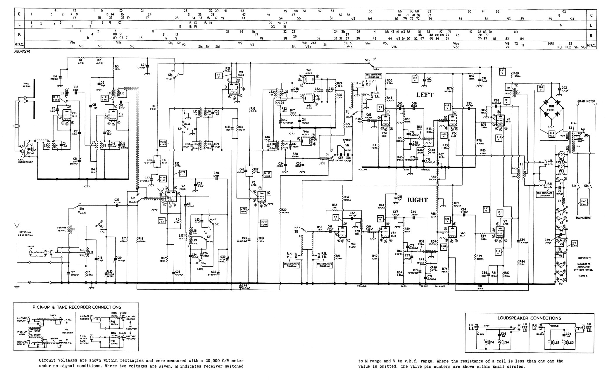
The original simplex stereo amplifiers used a pair of identical push-pull transformers in the design even though the second transformer was used as a single ended device with the main DC HT running through it. To avoid saturation of the SE transformer the PP transformers used were designed for a greater power than was actually required and thus the SE transformer was thus over engineered. In the Murphy A674SR Radiogram chassis two specially wound transformers were employed.
In the simplex concept, the amplifier is essentially a mono push-pull amplifier where the valves operate in anti-phase and thus the AC currents balance out and in a perfect implementation no AC appears on the DC HT rail. The output transformer primary load impedance a-a is given from the valve characteristics. For an EL95 this would be 10,000 Ω a-a. Theoretically, introducing the second transformer to this arrangement would produce no output in the secondary as the DC HT line has no AC component. If the valves carry an unbalanced signal as well as the balanced anti-phase drive from the phase splitter the two valves amplify the signal in parallel. The amplified signal is the same on both primaries and no AC is carried to the secondary. The DC HT rail has an AC component and the second transformer produces an output.
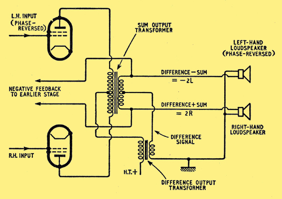
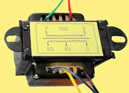
The above diagram and referenced article gives a clear description of the principles involved. If the unbalanced signal is amplified by the two valves in parallel the output transfer primary impedance required is half that of a single valve operating in Class A. For the EL95 this would be 5,000 Ω. The 3 Watt SE EL95 output transformer has a 10,000 Ω primary and is designed for a DC current of 24 mA. It does have a secondary tapped at 3, 8 and 16 Ohms. If the 16 Ω secondary is used with an 8 Ω load, the reflected impedance at the primary is the required 5,000 Ω.
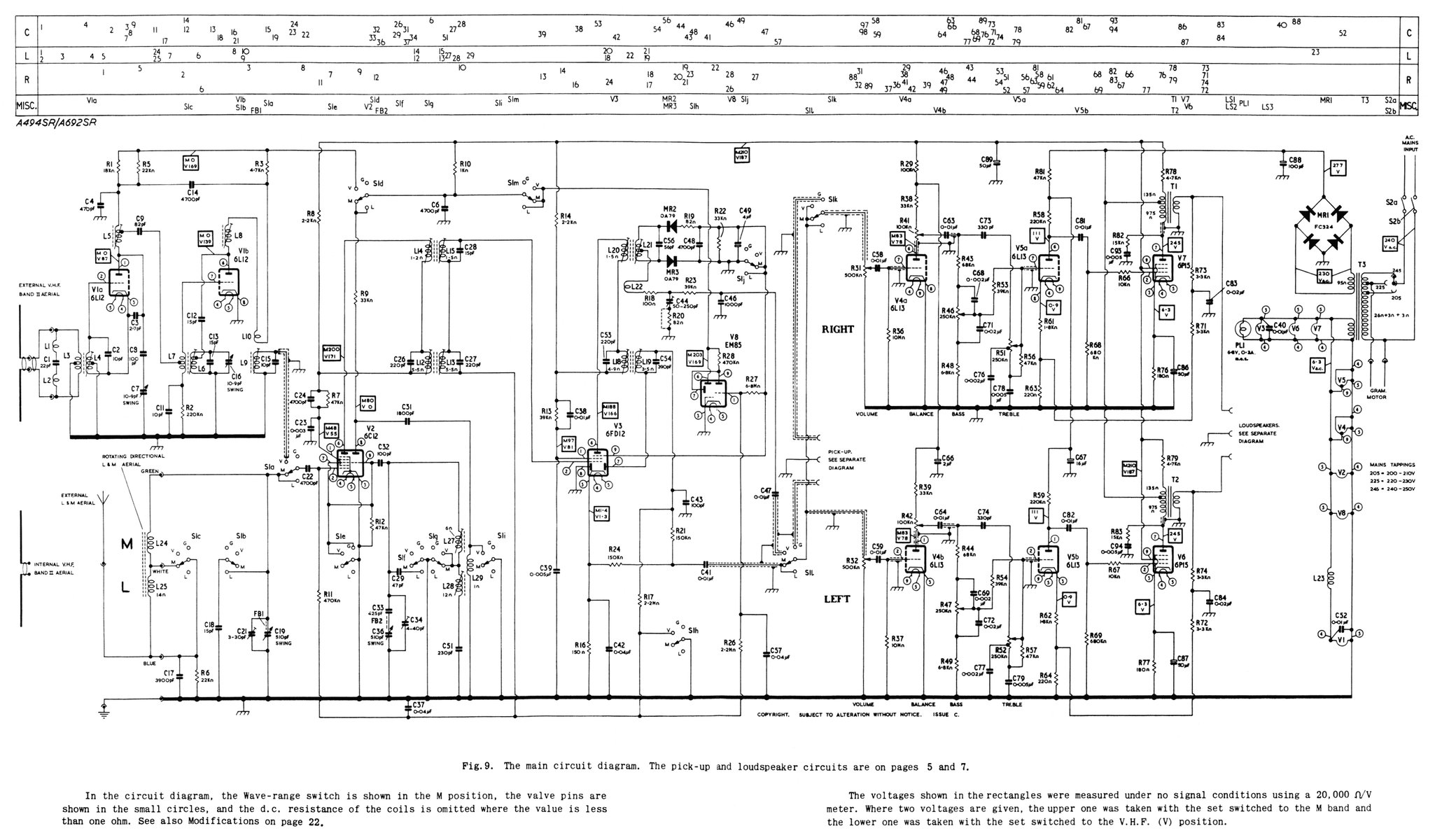
The original Stereoplex was designed for four wire ceramic stereo cartridges where one winding could be reversed. The Murphy radiogram was designed for use with a tape recorder as well as a turntable. With Left and Right signals from the tape recorder the amplifier the design used an inverter stage based on an anode follower and then a triode voltage amplifier to feed the output valve in one channel and the other channel used the triode and pentode without the inverter. A novel phase splitter in effect.
The test Class A 832A amplifier chassis contained an ECC81 phase splitter (based on the ECC83 Mullard design) and the output valve was operated with an 825 Ω cathode resistor that limited the HT input to 24 mA and the total dissipation to 7.5 Watts - half of the maximum for the 832A. This test amplifier is discussed more fully here.
Stage one of the experiment was designed to measure a new three triode phase splitter where one triode acts as an inverter. As the basic anode follower produces a gain of just below unity and through a mis-reading of the Murphy MKII circuit it was decided to build three nearly identical triode stages based on the 6AT6 double diode triode and to include a potentiometer in the anode load of the inverter to generate the unity gain required. This would also allow the circuit with parallel inputs to act as a straight phase splitter.
A three triode 6AT6 phase splitter?
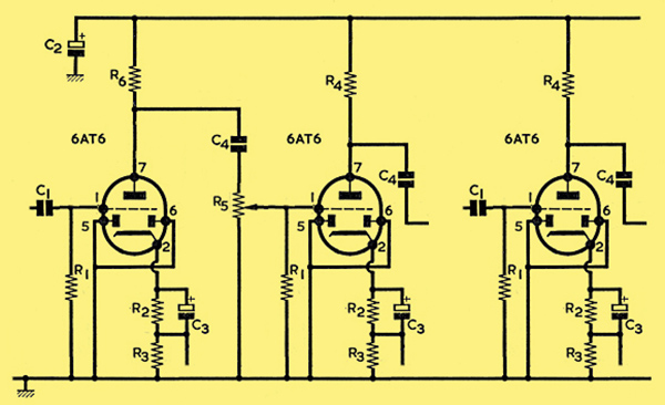
Conveniently the Neophyte Amplifier uses the 6AT6 to drive a 6BW6. The 832A can be roughly compared to a pair of 6V6's in a single envelope and the 6BW6 is a 6V6 on a B9A base. As the 6AT6 should provide adequate drive for the output valve it was decided to build the design as shown below using most of the component values from the Neophyte. The facility for injecting negative feedback was left in place for later experimentation. The inverter load consists of a 10 kΩ multi-turn trim-pot and a 180 kΩ resistor. This allows a small portion of the amplified signal to be extracted to feed the next stage.
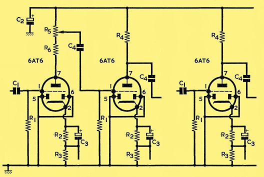
Circuit of the experimental phase splitter.
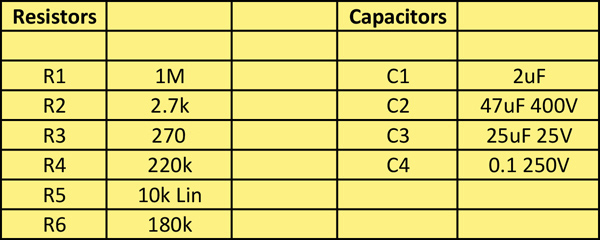
Component values.
The single 6AT6 stage operated with no issues. The second part of the circuit operated as a non inverting amplifier but even with DC on the heaters the stage had very significant hum pick-up. After much experimentation it was decided that the design was just plain wrong. Altering the circuit board was time consuming and initially components were hung from the board to test the alternative design.
The modified Circuit.
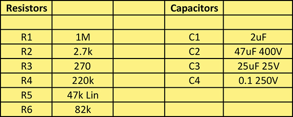
Modified circuit - component values.
There was no room on the board to insert an anode follower as the modification. Firstly the stage gain was reduced by lowering the value of the anode load. Secondly a multi-turn trimmer was fitted as an attenuator across the output of the first stage. A volume control. With 200 Volts as HT, the inputs paralleled and the outputs connected to the oscilloscope, the gain control was adjusted to give the second stage an equal amplitude to the first stage. Thus a three triode phase inverter existed that could replace the ECC81 stage in the experimental 832A amplifier chassis.
The gain balance is sensitive to changes in HT and a future refinement would be to stabilise the three triode board. As this circuit draws around 1 mA a simple Zener circuit should be adequate.
With the 832A connected to the push-pull EL95 output transformer and the HT adjusted to 200 Volts the new phase inverter was connected. The output to a single Mission speaker was distortion free. Thus the three triode circuit was functioning correctly.
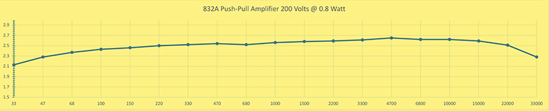
The unmodified 832A Push-pull amplifier with 200 Volt HT.
Next the 3 W single ended EL95 output transformer was wired into circuit following the connection pattern in the diagram above.
The secondary of the push-pull transformer has taps at 3 Ω, 8 Ω and 16 Ω. For the simplex circuit a pair of 8 Ω secondaries are required and so the transformer 8 Ω tap was used as the centre point and connected to the SE transformer's 16 Ω tap. The SE transformer's zero point on the secondary was taken as the centre point of the speaker connections.
The HT was connected to the start of the primary winding on the SE transformer. The other end of the primary connects to the push-pull transformer centre tap.
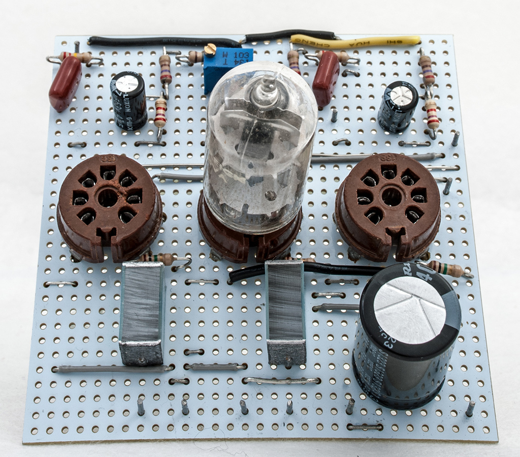
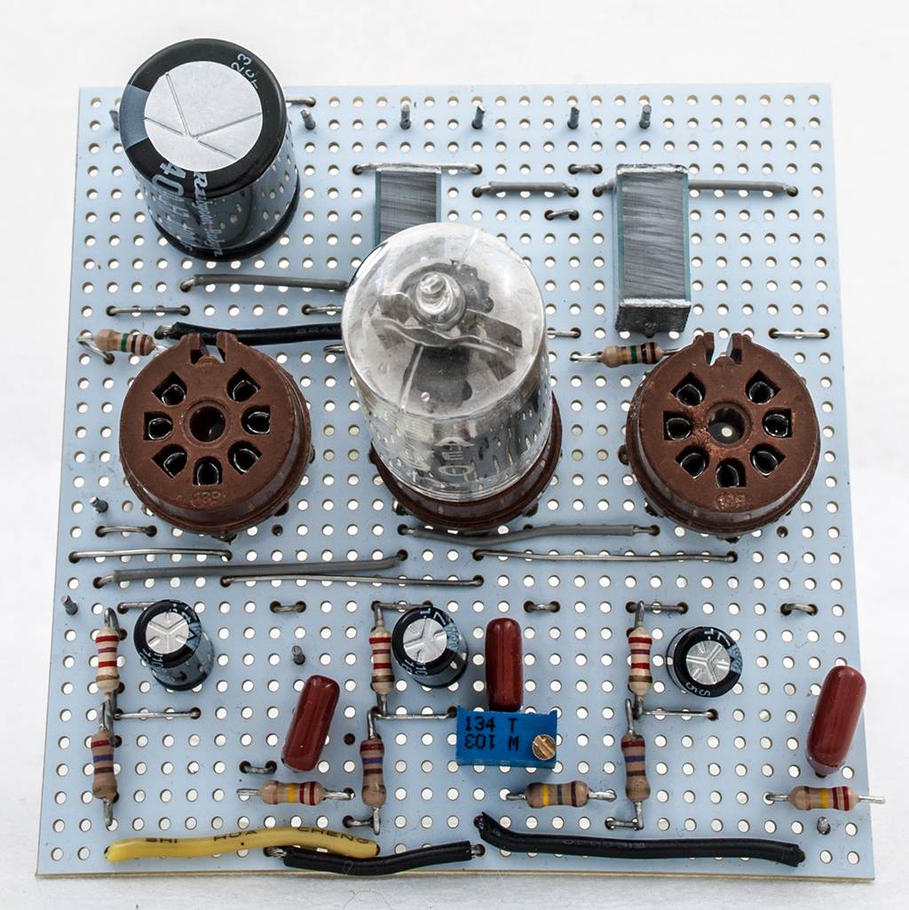
The 832A chassis with both output transformers.
The three triode circuit board was left on the jig and long leads used to connect the board to the 832A chassis. The ECC81 connections were removed but the grid stopper resistors remained in circuit.
The lash-up. Top right is the original 8 Ω dummy load.
The right hand speaker leads were reversed with the positive terminal going to the common point. The left hand speaker was connected conventionally with the common point connected to the negative terminal.
Initial testing was with both inputs paralleled. The mono signal appeared across both Mission speakers. Sounded fine.
The SE transformer secondary connections were reversed and the amplifier powered again. The sound was muffled and clearly the way the transformer is connected matters.
The next step was to connect a stereo source to the inputs. An on-line 'left speaker, right speaker and both speakers' test was used. The test functioned perfectly with no indication of cross-talk - quite a surprise.
Time for music. Pieces were selected that emphasised channel separation and pure mono. The sound separated in the same way as a dual amplifier stereo set-up and the mono appeared between the speakers. Subjectively a good result.
Time to use the test equipment to see exactly what was happening.
The measurements with 200 Volts HT on the 832A were disappointing. The oscilloscope trace indicated that the bias was too high. The phase inverter was taking 1.3 mA and so a 47 kΩ resistor would drop sufficient volts to allow the 832A to run correctly. Also a new dual dummy load was made so that both channels could be monitored simultaneously.
With the 47 kΩ resistor in place the HT was increased until 200 Volts appeared across the phase inverter. This produced 253 V at the centre tap of the PP transformer and 265 V at the top of the SE transformer primary. The 832A would normally be run from 250 Volts HT.
With a stereo source connected to the inputs the amplifier sounded correct. A left-right speaker test gave the impression of adequate channel separation.
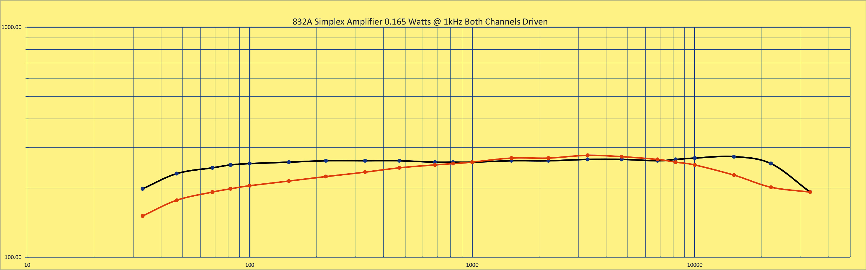
With the function generator driving both channels, 8 Ω dummy loads were connected to the speaker terminals. The oscilloscope inputs were connected to the dummy loads. The input was a 1 kHz sine wave at a level of 100 mV.
Speaker voltage with both channels driven in parallel.
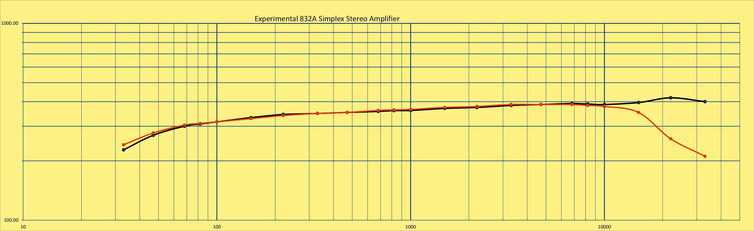
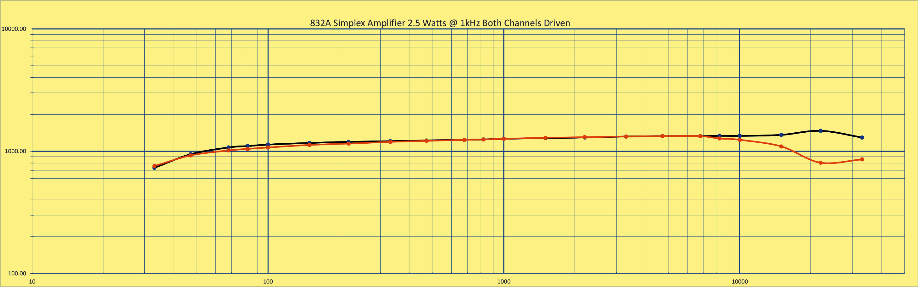
The muli-turn trimmer was adjusted to give equal voltages across the dummy loads. Readings were taken at different frequencies and plotted on a log log graph.
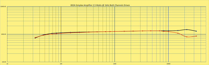
Speaker power (mW) with both channels driven in parallel. Right channel is red.
To find the channel separation the function generator was connected to one channel with the other channel shorted to ground. The output from a single channel was 500 mW and the un-driven channel output was 15 mW. This gives a power ratio of 34 and in dB a separation of 15.3 dB. The original Stereoplex claimed 25 dB. However, with a music source or a Youtube test video the stereo image sounds the same as the 6P3P SE desk amplifier.
The small EL85 SE transformer was rated at 26 mA and so running the 832A at a small DC input was only going to give a low output and thus not a true reflection of what was possible. The FU-32 SE Amplifier was re-measured to give a reference for two channel output from one 832A valve. About 2 Watts per channel. The mono PP 832A amplifier with an ECC81 phase splitter gives 5-6 Watts.
To conduct test properly the 'lash-up' needed replacing with a proper breadboard. This would provide access to alter the circuit whilst being safe to work on.
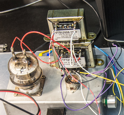
The new SE transformer.
The EL95 SE transformer was wired to give a 5 kΩ primary and 8 Ω secondary. A Chinese output transformer (looking like the ones used in the FU-32 amplifier) was purchased. This was not an expensive component. This was designed for 5 Watts with a 5 kΩ primary - safe for 50 mA DC. The 832A circuit was replicated, the cathode resistor for the 832A was 330 Ω to give a 17.5 Volt bias, and the three 6AT6 triode phase inverter used to drive it.
The 832A needs a maximum of 200 Volts on the screen and the phase inverter needs a constant voltage. The small Veroboard circuit to the left of the output transformers is the Screen supply. A 180 Volt 5 W Zenner diode is fed from the main HT rail by a 10 kΩ resistor. The output is smoothed by a 47 μF capacitor. It was measured on load and gave 183 Volts.

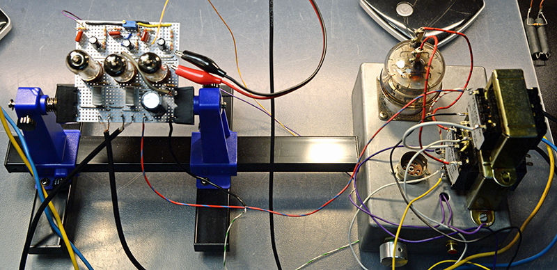
The completed breadboard with EL95 PP transformer and the new SE transformer.
Time to try the amplifier. Subjectively with the Mission speakers the sound was excellent with good separation and more than adequate volume. Measurements were another matter. The inputs were strapped together and a sine wave applied to both. The output power was low and the waveforms not identical from each channel. Much testing and re-building followed but the objective performance did not improve. A long listening test was, however, more than adequate.
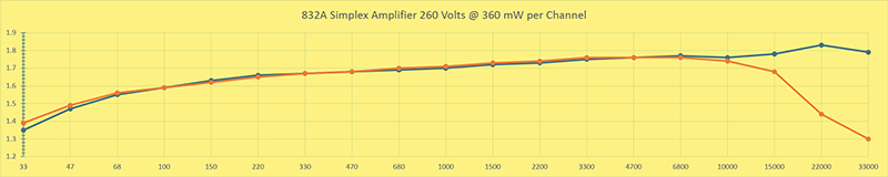
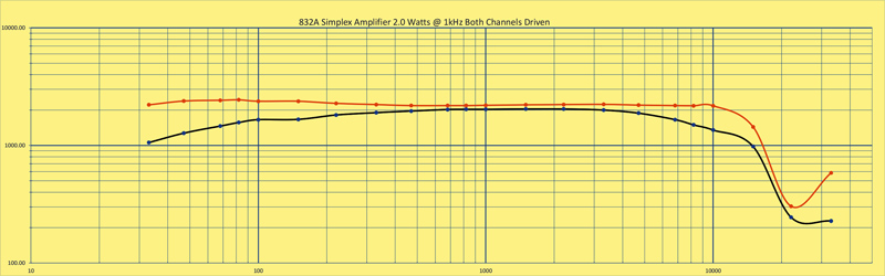
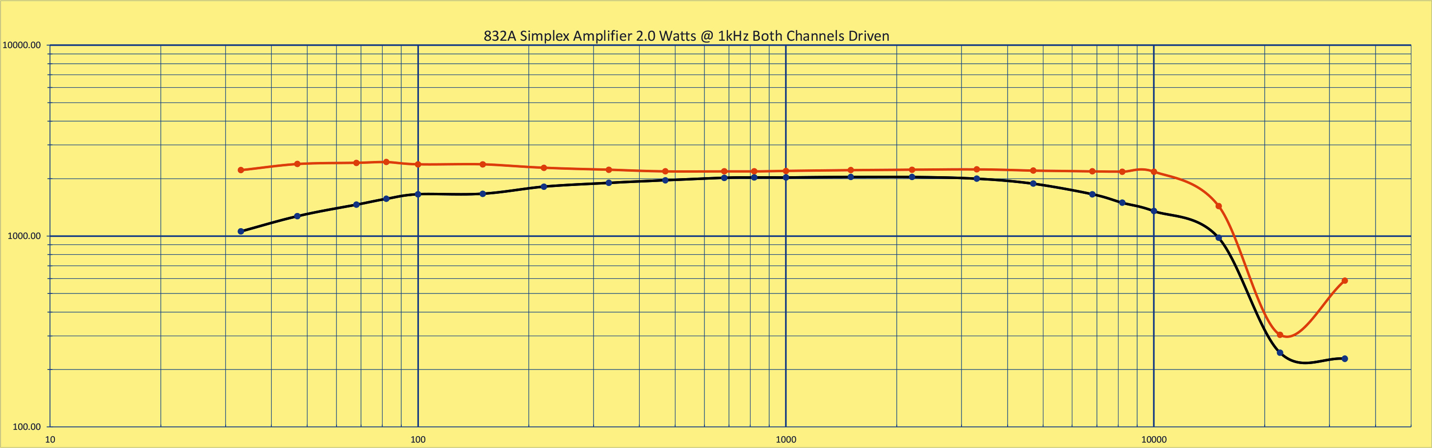
The simplex amplifier with 13.5 Watts DC input. Two times 1.5 Watts out.
The basic 832A amplifier has produced 6 Watts output but when the SE output transformer was correctly connected the output per channel dropped to roughly 1.5 Watts for the same input power (250 Volts at 50 mA or 12.5 Watts DC). The amplifier was reverted to the push pull configuration and the output confirmed as 6 Watts or thereabouts. Next the SE output transformer primary was connected between the HT rail and the centre tap of the output transformer. The secondary being only connected to the oscilloscope.
With the input sine wave at the amplitude for driving the PP configuration to 6 Watts the HT was applied. A very low level distorted signal appeared across the load resistor and a series of peaks appeared across the SE transformer secondary. The input signal amplitude was reduced until a clear sine wave appeared across the load. At this point a waveform at twice the 1 kHz input frequency was seen across the SE transformer secondary. The maximum undistorted amplitude across the load was consistent with the 1.5 Watts seen in the simplex amplifier.
The next stage was to re-wire the amplifier as two SE stages using the EL95 SE output transformers. Without altering the bias or HT the new configuration was powered-up. Here the output was less than 1.5 Watts per channel and the distortion was higher than in simplex mode. The second harmonic was less than 11 dB down on the fundamental whereas for the simplex configuration the second harmonic was at -22 dB. No negative feedback was applied in either case.
The author had checked the anode waveform of the push pull amplifier and it was a sine wave - a clear indication of Class A operation. In the push pull mode each half of the output transformer is driven by an equal and opposite amount and the load voltage is 7 Volts equal to 6 Watts. In the single ended mode or the simplex mode the load voltage is half of this or 3.5 Volts equal to 1.5 Watts.
The simplex amplifier had a channel separation of 15 dB. The twin SE version gave no measurable output from the channel with the shorted input.
The SE amplifier with the three triode phase inverter was then given an extended listening test. The second speaker had the phase reversed to remove the signal inversion. The channel separation seemed the same as the simplex with a stereo source. The 6AT6 gave more than adequate amplification and the amplifier required only half the signal needed for the 832A mono amplifier.
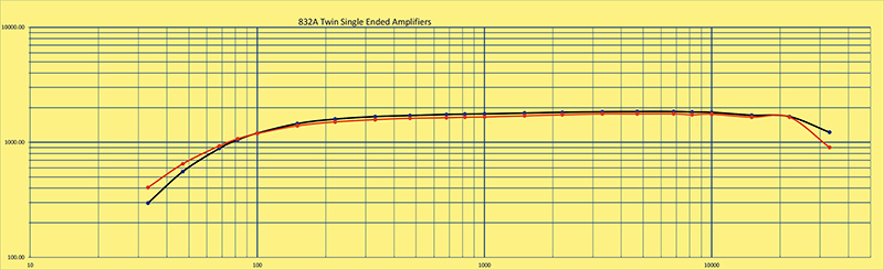
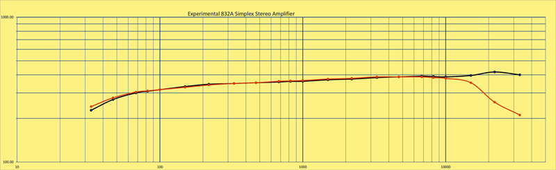
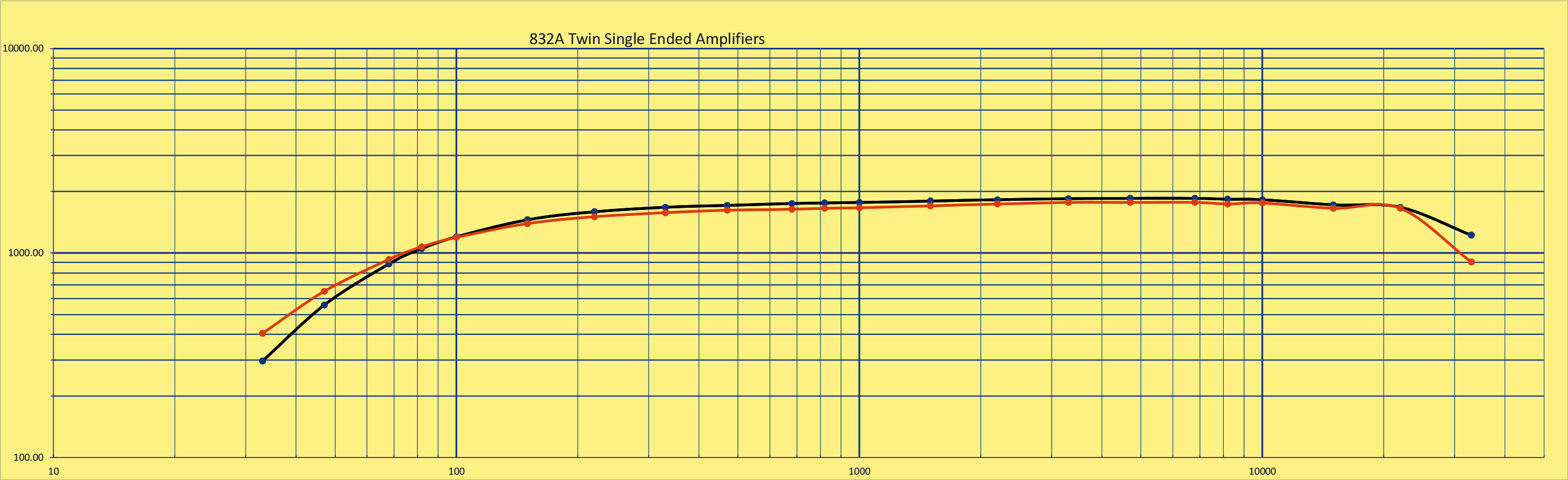
The twin SE amplifier with 13.5 Watts DC input. Two times 1.7 Watts out.
The twin SE amplifier with the VVT EL95 SE transformers wired for 5 kΩ primary and 8 Ω secondary was measured as shown above. This output was achieved with 18% THD and really needs some feedback to improve the functionality. It should have been much closer to the FU-32 amplifier.
The twin SE configuration showed that the simplex circuit gave a similar output but with better THD performance and poorer channel separation. Subjectively there was not too much difference.
As a further test the PP transformer was replaced by a 10 Watt ECL86 output transformer. The primary impedance being 8,500 Ω a-a.
The author was interested in the fact that with equal signals on both channels the oscilloscope trace showed a signal on the SE transformer where theoretically none should exist. As an experiment, the connection to the PP output transformer centre tap was fed from the 4 Ω point on the SE transformer in place of the 8 Ω tap. The distortion increased. By using the 4 Ω tap the reflected primary impedance had doubled and the distortion worsened.
Remembering the circuit diagram of the Murphy radiogram, the output transformers were marked with the winding resistance. The PP transformer being 200 Ω per side. The SE transformer was marked 140 Ω. Making the assumption that the impedances were directly related to the winding resistance, the SE transformer primary impedance was calculated knowing the PP load for a pair of EL84's. If the PP required 8 kΩ a-a then the SE transformer impedance became 2.8 kΩ. The data-sheet gives the anode load for a SE EL84 as 5 kΩ and thus a pair in parallel would be 2.5 kΩ. Close to the Murphy design.
If the new PP transformer was 8.5 kΩ a-a the SE transformer impedance should be 2,975 Ω. Clearly the new 5 kΩ transformer was not correct. With a VVT 5 Watt 5.2 kΩ SE EL84 transformer in the 'junk box', the 16 Ω tap used for 8 Ω would give a reflected primary impedance of 2.6 kΩ - worth trying.
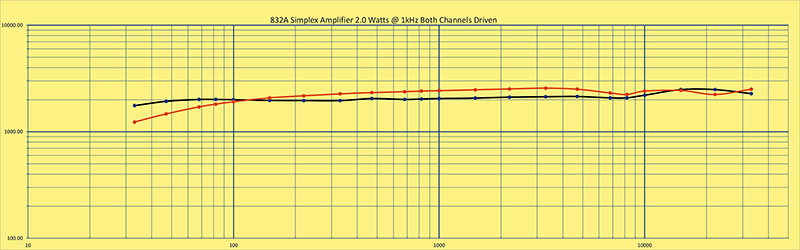
The simplex amplifier with 13.5 Watts DC input. 2 x 2 Watts out.
The test of the new set-up gave an output voltage across the 8 Ω load of 4 Volts - 2 Watts output. One channel showing as a near perfect sine wave and the other channel slightly degraded.
Listening to this version was a great pleasure. The sound stage was broad and correct. The sound was clear and distinct.
The author purchased a mono PP EL84 amplifier BH 14 many years ago that needed the capacitors replaced - never done. The output transformer was of the shrouded upright type and physically matched the SE transformer. Time to remove it and try it in the simplex.
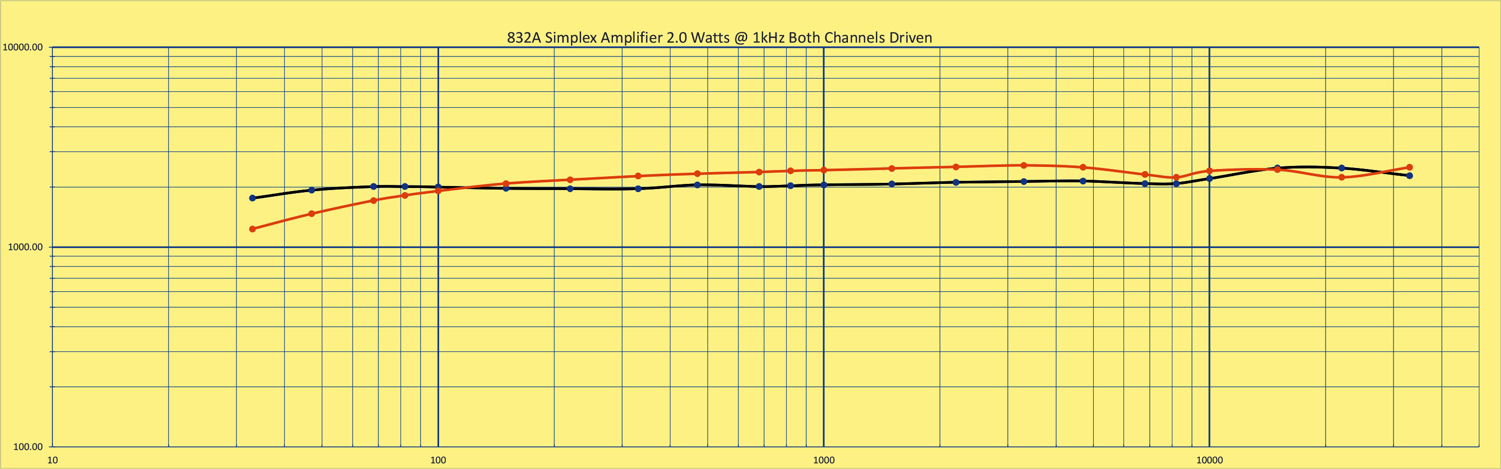
The simplex amplifier with 13.5 Watts DC input. 2 x 2 Watts out.
Listening to the amplifier with the 1960's PP transformer was a delight. Monitoring the voltages on the loudspeakers at normal listening volume suggested that less than a volt RMS was being generated. This equates to a total of 0.25 Watts into the speaker pair. Almost no distortion at this volume. For the graph above the signal input was raised to the point when the curves just flattened. The 2nd harmonic content was down at -13 dB on the fundamental. The third and fourth harmonics were below 35 dB with respect to the fundamental. Too much second harmonic. Changing the cathode bias resistor to 400 Ω the 2nd harmonic dropped to -30 dB.
Changing the modern 10 Watt PP transformer for the older component significantly increased the second harmonic content at extreme signal levels, but at lower levels the amplifier sounded most acceptable and compares favourably with the 6P3P SE amplifier in the office. The amplifier with the pair of shrouded transformers would look better than the amplifier with transformers that did not match visually.
Overall the final iteration of the simplex amplifier makes for a worthwhile project and provides a good listening experience. It is also a useful way of employing output transformers that are not part of a pair. In the author's case the two shrouded transformers now have a purpose.
Comparing the twin SE EL95 output transformers with the final version was a little unfair as the SE EL95 transformers were physically smaller and designed for 3 Watts output. More iron equals better bass response.
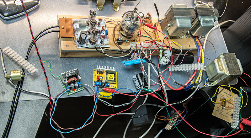
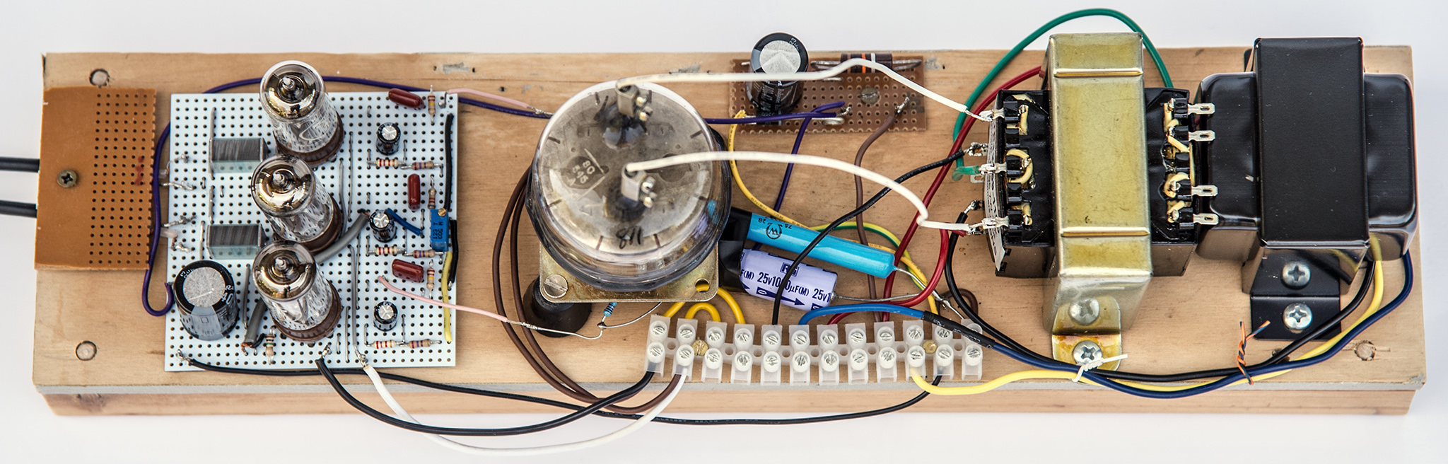
The simplex amplifier now mains powered.
In the junk box since the mid 1960s has been a mains transformer with a secondary rated at 20 - 0 - 20 Volts at 1.5 Amps. In the above image it is at the bottom right and is being abused by supplying 1.8 Amps. The desire was to use this transformer to power the amplifier as then all three transformers would be a close match aesthetically. A pair of 3 Amp silicon diodes in a two phase rectifier circuit feed a 10,000 μF capacitor. The DC at 21.6 Volts then powers two DC-DC converters. Both of Chinese origin. The one on the left steps down to 6.3 Volts and the one on the yellow PCB steps up to 320 Volts See Using Cheap DC-DC Converters. The two blue wire-wound resistors are a pair of 825 Ω 1% types connected in parallel for the cathode bias. At present the bias capacitor is a 40 Volt 4,700 μF type. The transformer at top right is the SE 5 W EL84 and the one next to it is the early 1960s 10 W PP EL84. The extra HT required an increase of the dropper resistor in the 180 Volt board to 16.8 kΩ.
The final amplifier has been playing Pink Floyd as the author completes this article. It does it rather well!
The final amplifier showed that the simplex stereo configuration works well but not better than a pair of single ended amplifiers. The latter have, on paper, much better channel separation. Two matching sets of components make more sense and the expected increase in overall power on a mono signal was not seen to be significant. The sound in a room 7 x 4 metres was, however, superb.
The author was still curious about the original early 1960s designs. Thus the Murphy A274SR chassis was put on test. With a push pull pair of EL84s the power expected from a mono signal was tested. Would it be 10 Watts? In fact it was little more than 2 plus 2 Watts.
The 832A pp amplifier with either the ECC81 phase splitter or the three triode phase inverter produced over six Watts of good quality audio. A pair of such amplifiers would have a joint power close to 15 Watts on peaks. Saving on everything but expensive output transformers to build a simplex stereo amplifier would deliver a combined power output or no more than five Watts on peaks.
Simplex stereo is unlikely to make a comeback in home construction or commercially.
Postscript
Building a 6V6 single ended ultra linear amplifier (See here ) without the correct output transformer, the author experimented with the EL95 PP transformer using the centre tap to feed the screen grid. At 50 mA the core had not saturated. Back to the stereoplex design with two push pull transformers.
Looking at the original article the author noticed that whereas he had used the 8 Ω tap as the centre point, the correct answer was to use the 4 Ω tap as the centre point.
Both transformers were put into the circuit and the wiring followed exactly the stereoplex circuit.
Listening alone gave the opinion of a great sounding amplifier with good stereo separation and more than adequate power - much louder than expected - deafening in fact.
Measurements told a different story. At 2 Watts per channel the THD was at 28%. At 160 mW the THD had dripped to 8% with only the second harmonic appearing above the noise.
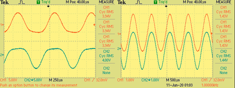
The oscilloscope traces - 28% THD and 8% THD. The lower channel is inverted on the left image.
The DC conditions were measured as: Rk 416 Ω Vk 16 Volts, Va 300 Volts and VHT 303 Volts. The DC input being 38 mA at 284 Volts or 10.8 Watts. The common screen grid was at 180 Volts.
The plot is shown below.
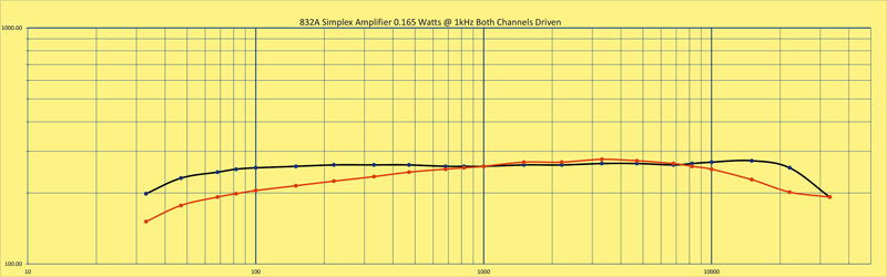
The simplex amplifier using two push pull transformers.
References
- A Two-Way Stereophonic Amplifier by B B Bauer, J Hollywood and G Maerkle, Audio, October 1958.
- Bi-Ortho Output Circuit. C Nicholas Pryor, Audio, November, 1958.
- Single Amplifier Stereo, Wireless World, January 1959.
- The Stereoplex by H Kolbe, Popular Electronics, April 1959.
- Simplex Stereo in the Murphy A674SR Radiogram. The circuit diagram of the MkI can be found here and the MkII here.
| 