|
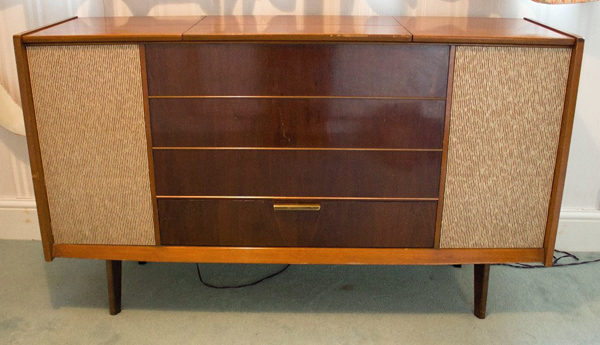
The Murphy A674SR mk I radiogram from 1961.
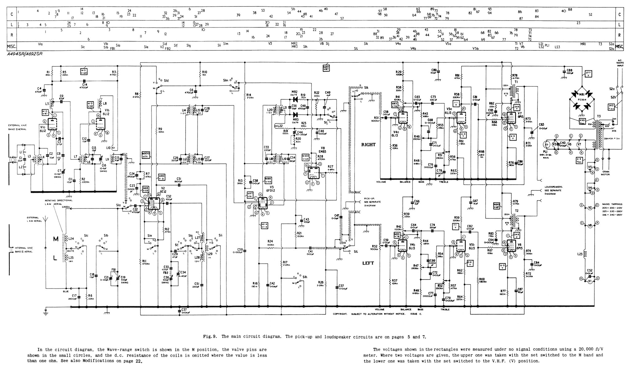
The Murphy A674SR radiogram from 1961 replaced the 1958 A494SR seen below and featured a 'Phantom' amplifier rather than two single ended amplifiers.
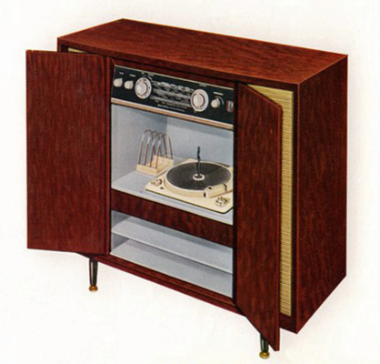
The A494SR had two single ended EL84 audio amplifiers. Image courtesy of Murphy-bilia
The phantom amplifier or simplex stereo was developed in the 1950s to deliver maximum power from two output valves. A single ended EL84, for example, produces around 3 Watts but a push-pull pair will produce 10 Watts of audio. It was known that the L + R signal has much more power than the L - R signal. L + R is mono and so were most of the signal inputs of the day.
The simplex concept was developed many years before as a way of adding another signal to a balanced telephone line. Originally the technique used only transformers but it works just as well with active devices.
In amplifier terms the L + R signal or mono signals are amplified by a push-pull amplifier. That amplifier is modified and a second output transformer introduced as per the simplex topology. An L - R signal is then amplified by the output valves working in parallel. De multiplexing at the transformer secondaries restores the L and R signals for the loud speakers. The total output power available is equal to the output of the push-pull pair.
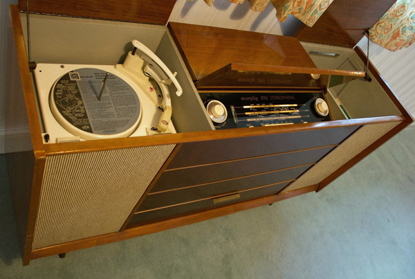
Garrard type RC210 changer unit with Garrard GC8 mono or Acos GP71 stereo cartridge. The right hand compartment was intended for housing a tape recorder. The base is ventilated and phono connectors are built into the side wall.
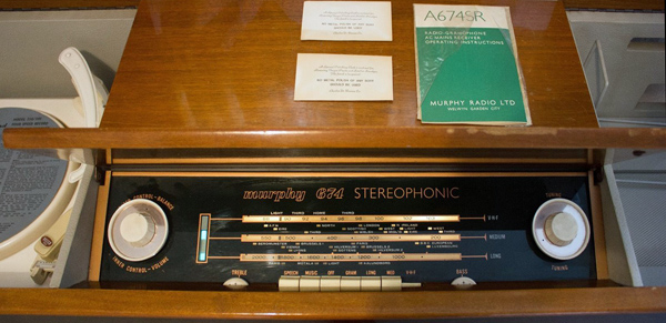
The electronics are contained on a single chassis mounted at a slight angle to the vertical with a fold-up lid. Typical of Murphy Radio is the substantial and well finished cabinet.
The Mullard equivalent valves used are: ECC85, ECH81, EF89, EABC80, EM84, ECC83(2) & EL84(2).
April 2020 during the Corona virus lock-down proved to be amplifier month. As part of the re-visit to simplex stereo, the performance of the A274SR was measured.
The A494SR from 1958 had employed twin SE EL84 audio amplifiers for a quoted 3 Watts per channel. The 1961 A274SR boasted about using a simplex stereo amplifier that amplified mono recordings through a push-pull amplifier - the implication of a performance usually found in high end and thus more expensive systems. The later A274SR MKII reverted to the twin SE EL84 amplifiers.
The test set-up was identical to the measurements made on the 832A Simplex amplifier.

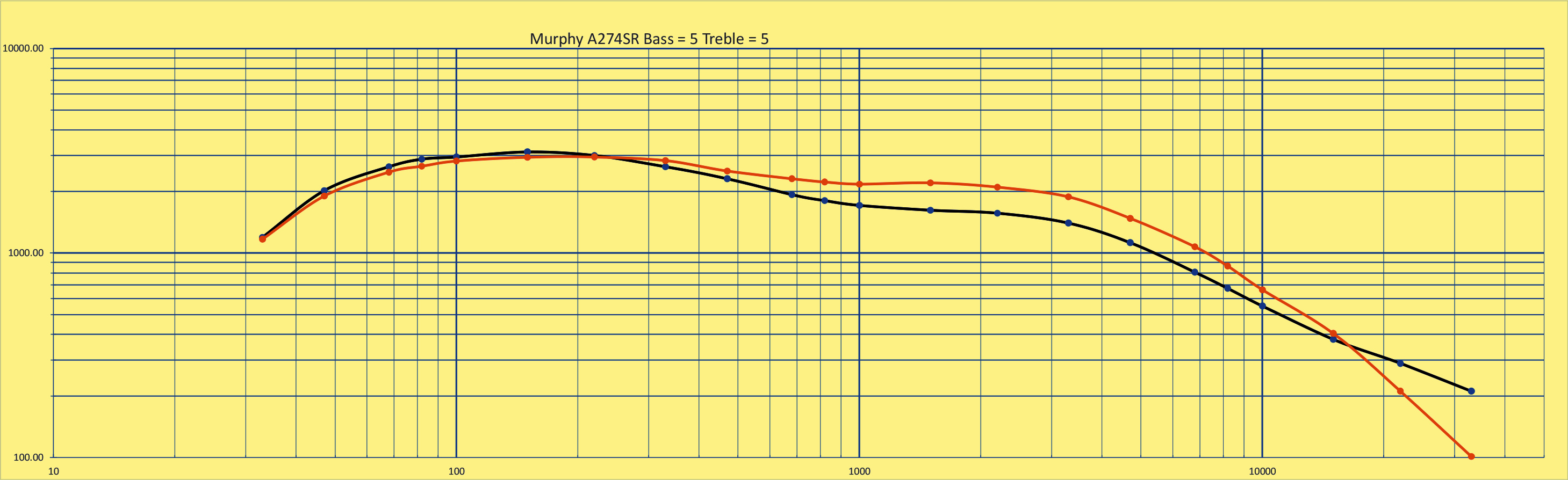
A274SR with the tone controls set to mid point - 5 on the scale. Output measured on 8 Ω load resistors.
The above performance graph was a revelation - low power and a skewed frequency response. However, the cross-talk was down at 29 dB. The measurements were with an 8 Ω load and with a 4 Ω load the power was 3.3 Watts.
With the advantage of having test equipment the balance control was set to give equal voltages across the load resistors at 1 kHz. The setting ended up being to increase the output from the right channel. In use the balance control had been set to the mid point, just as the tone controls had been.
It was also noticed that the speakers were out of phase. Originally both of the speakers had been wired the same. In fact one should have had the connections reversed as the algebra of the simplex system produces 2R and -2L.
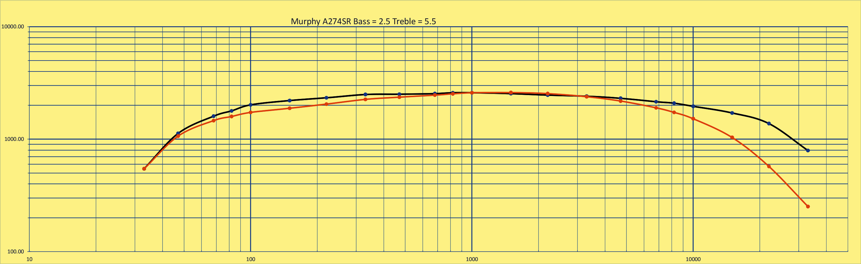
The next adjustment was to set the output voltage at 100 Hz and 10 kHz to the value at 1 kHz by altering the tone control settings. Thus it was hoped that a flat response could be achieved. The result is shown below.
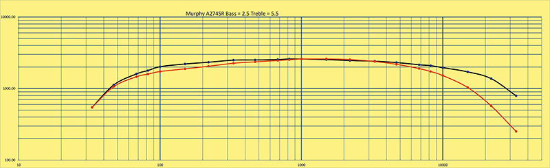
A274SR with the tone controls set to a flat response into 8 Ω load.
Experiments with the 832A simplex amplifier indicated that getting equal responses from both channels required careful adjustment of the gain of the phase inverter. The A274SR required the same care. The output power for a mono signal was no improvement on a pair of SE EL84 amplifiers. In this implementation with left and right amplifiers the component count was little different between the MKI and MKII versions. One was left with the impression that simplex stereo or phantom stereo added more to the marketing brochure than the audio.
A critical look at the output transformers revealed them to be much smaller than that required for 10 Watts, in fact they look much like three Watt devices.
References
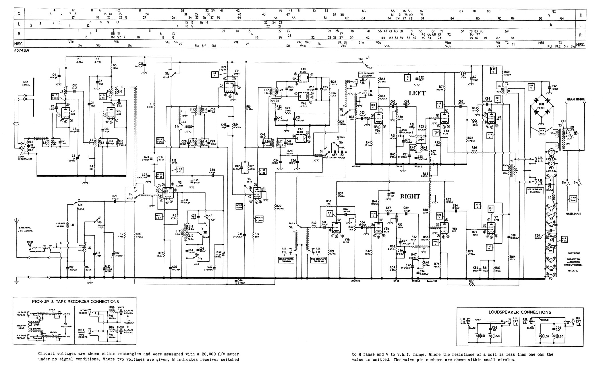
- The circuit diagram: MkI here and MkII here. The MkII uses a pair of SE output stages.
- Murphy-bilia & 3002.
- Single Amplifier Stereo
- The Stereoplex
- Simplex Stereo Re-visited
| 