|
A mid 1930s metal can 6V6 had been sitting on the author's desk. Time to use it.
The 3A/158M amplifier was a disappointment and the circuit was removed from the breadboard. By chance an IO valve-holder was an exact fit to the holes left by the B8B valve-holder. All the components for the 6AT6 circuit from the Neophyte amplifier were still on the bench and a 6V6 was to hand. Time to play.
The single ended 6V6 output was found in many domestic radios from the mid 1930s onwards and produced a good sound with adequate output power. A basic circuit was built and the output transformer used was the VVT Transformers [★] no longer trading device used for the paralleled 3A/158M. It was designed for an EL95 single ended three Watt circuit. The 16 Ω tap was used for the 8 Ω load to give an effective primary impedance of 5 kΩ. The 6V6 screen grid was taken to the 160 Volt rail used for the 6AT6. The circuit worked well but the power was down at around 1.5 Watts. What about improving the design with an ultra linear connection of the 6V6.
Whilst looking for a suitable transformer the author found Matt Renaud's Cascade Tubes site and an article on 6V6 SE Ultra Linear Bias Optimization. Matt's work is excellent and comprehensive.
As no suitable transformer was available in the 'Junk Box' or available commercially at a reasonable price, it was necessary to experiment. The VVT PP EL95 7 Watt transformer was to hand. The 6V6 screen grid should be connected to a 43% tap but 50% would have to do. The question of saturating the core with the DC through the primary would have to be found on test.
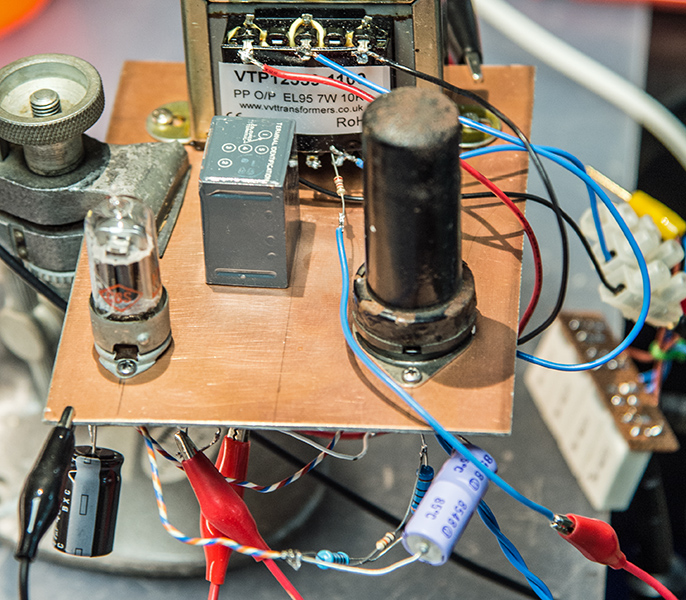
The prototype amplifier. The interstage transformer is not used.
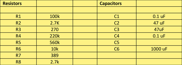
The cathode resistor is made from three resistors to get the exact value of 389 Ω to suit the 250 Volts on the anode.
The circuit of the Neophyte amplifier with the tone controls removed and the 6V6 cathode resistor set to 389 Ω bypassed with a 1,000 μF capacitor was built.
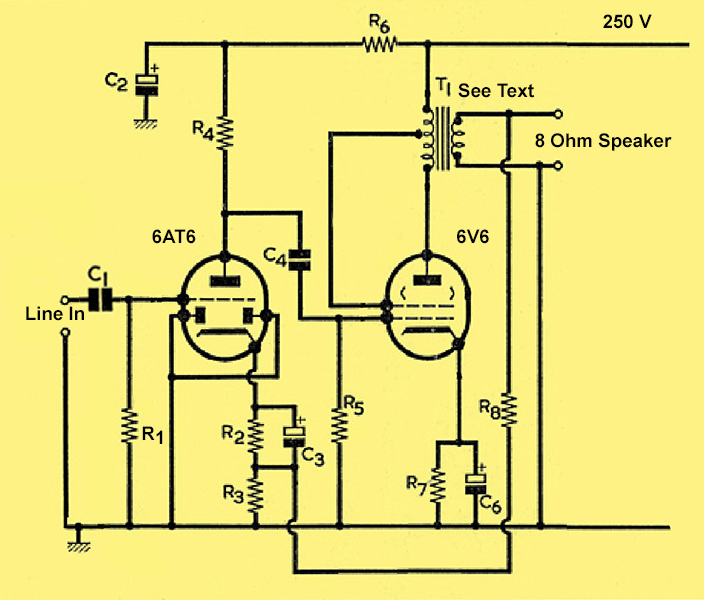
The circuit diagram.
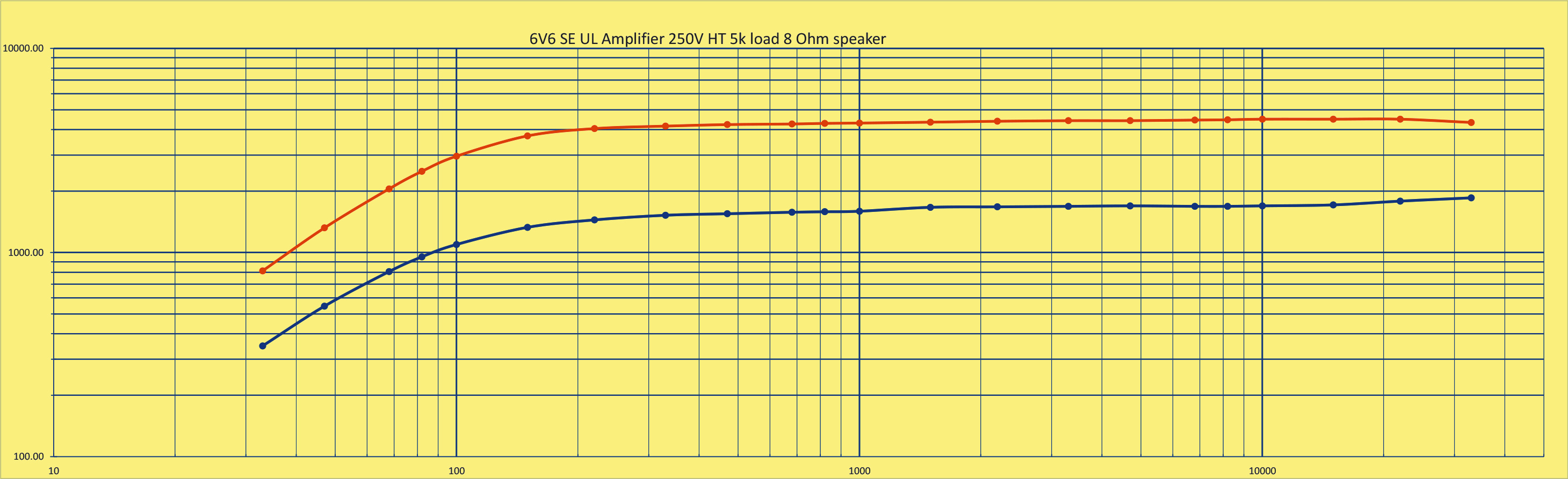
Listening to the amplifier was a joy with clear sound and adequate volume. Time to measure what was being produced. The operating conditions were as follows: Vin 1.65 Volts pk-pk, Va 250 Volts, Vk 13.75 V with no signal. Measuring the THD gave 2nd Harmonic -32 dB, 3rd - 40 dB & 4th down in the noise. This gave a THD of 2.72%. No sign of core saturation was observed.
To look at the headroom for core saturation the 6V6GT was replaced with a KT66 without changing the circuit. The input was adjusted to the point where the output curve just flattened which gave: Vin 2.65 Volts pk-pk, Va 3000 Volts, Vk 24 V with no signal. Measuring the THD gave 2nd Harmonic -30 dB, 3rd - 44 dB & 4th again down in the noise. This gave a THD of 3.23%. No sign of core saturation was observed.
The output power for both configurations is given below.
The performance with 6V6GT and KT66.
The RMS power to a dummy load was not spectacular, however, the subjective performance in a 4 x 7 metre room was excellent. The amplifier was tested with an original metal 6V6 and the Brimar 6V6GT as well as the KT66. Worth a build.
The KT66 had a cathode current of 60 mA without the 7 Watt transformer saturating. This demonstrates why the original Stereoplex Simplex Stereo design could use two push pull transformers.
|