|
This amplifier project has had several iterations over the past decade.
Over the years the author has purchased quite a few transformers from VVT Transformers [★] no longer trading for various amplifier projects for the museum including A Valve Amplifier for the Study and A 600 mW Low Power Amplifier based around the Firefly design. Initial experiments with 832A double VHF beam tetrodes utilised an old Majestic output transformer and an 820 Ω cathode resistor. This low power amplifier produced a most acceptable quality and volume and allowed recent experiments with Simplex Stereo.
Time to upgrade the experimental chassis to get more from the 832A. A pair of EL95's in push-pull are a close approximation to the 832A and a pair of transformers for 7 Watt output were ordered from VVT Transformers. A Chinese FU-32 SE amplifier kit was built by the author and the undistorted output was measured at 2 Watts per channel. What would the push pull amplifier do?
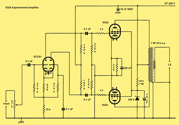
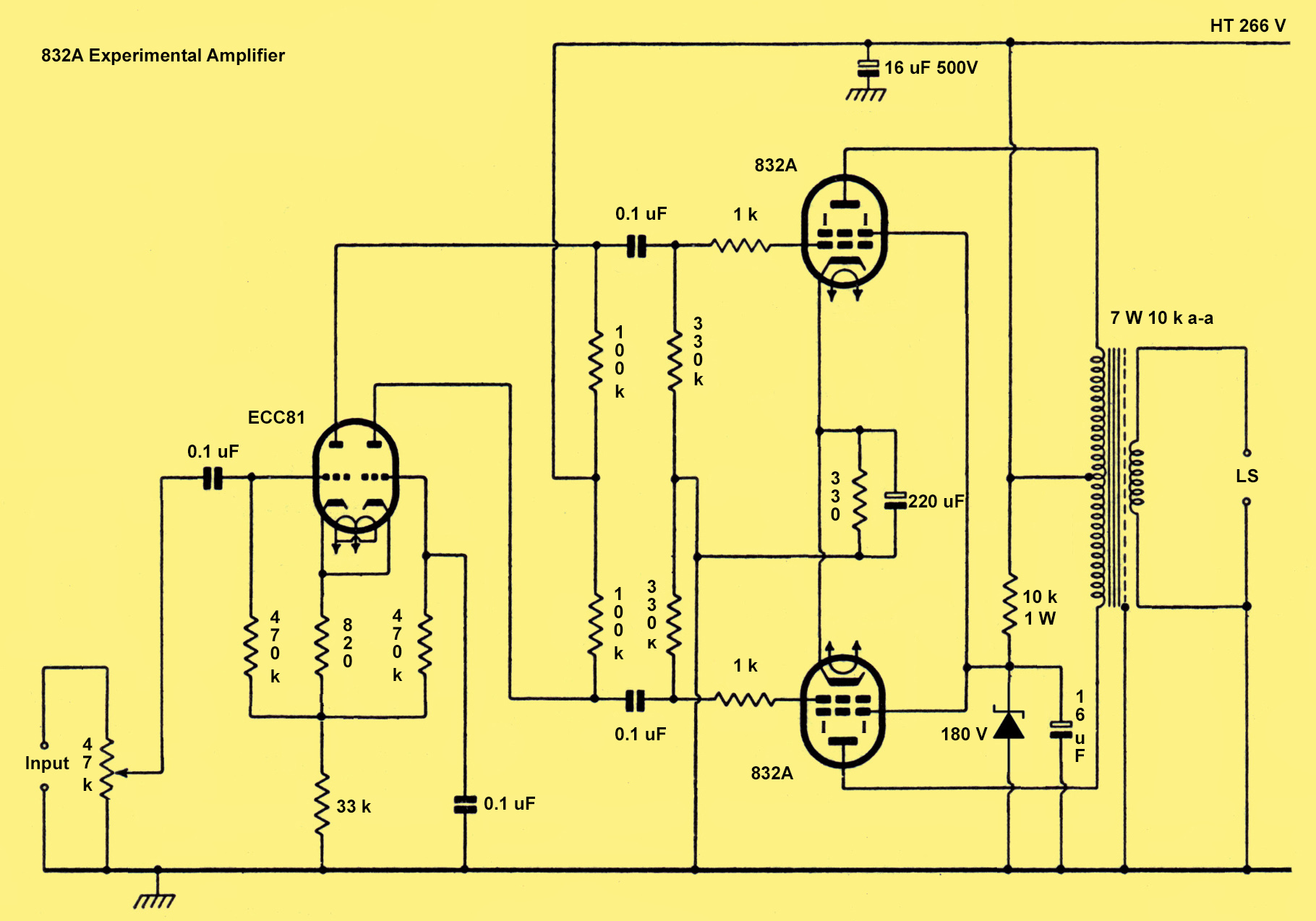
Circuit diagram.
The circuit is not complicated and at the present iteration has no negative feedback. The signal source was intended to be the line output of the main computer and so no pre-amplifier valve was included. The phase splitter design is taken from the Valve Technology series by Graham Dixey. The cathode-coupled circuit was chosen. Testing with ECC83, then ECC82 and finally ECC81 suggested that the medium gain ECC81 was the better performer. This is in keeping with opinions of other experimenters.
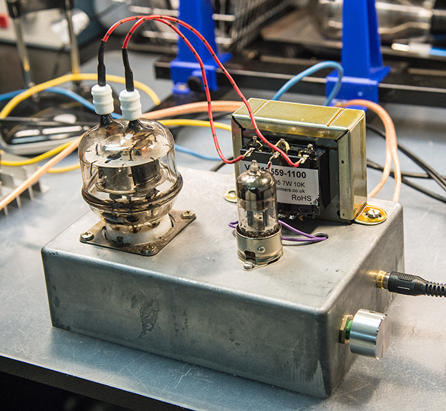
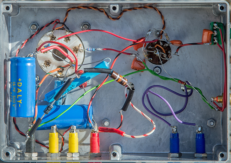
The completed amplifier under test.
The 832A stage uses a 330 Ω cathode resistor bypassed with a 220 μF capacitor for self bias at 16.5 Volts. The total cathode current is 50 mA with an anode to cathode voltage of 250 Volts. The 832A is thus run in Class A with a standing dissipation of 12.5 Watts. Comfortably within the 15 Watt maximum. Grid stopper resistors were mounted as close as possible to the valve grids to prevent oscillations. These are VHF valves by design. Initially for the low power amplifier the common screen grid was fed from the HT rail by a 33 kΩ resistor. The 6P3P SE amplifier runs the screen grids from a Zener diode stabilised supply and the data-sheet indicated that the 832A should be run with the screen grid at no more than 200 Volts. A 180 Volt Zener bypassed with a 16 μF capacitor now supplies the screen grid.
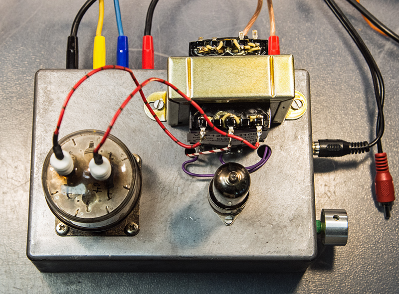
Top view. HT, Heater and LS connections are made by 4mm Plug/socket. Phono input on right.
All coupling capacitors are 0.1 μF as these were available in the 'junk box'. Most resistors are 0.3 Watt. Exceptions are the screen dropper and the 832A cathode resistor. The latter is a precision 1% wire-wound type as this was also 'in stock'. Only the output transformer and the Zener diode were purchased specifically for the project. The author now has many amplifiers and this project was considered unlikely to ever be built as a mono bloc pair as originally planned.
As the capacitors were chosen due to availability it was not expected that the amplifier would be of optimal performance.
Construction
An inverted die-cast box was chosen as a convenient chassis. Suitable holes for the valve holders, connections and the volume control were formed. The spacing for the fixing holes on the original Majestic output transformer luckily were still correct for the VVT replacement.
VHF practice of bringing all ground points of a stage to a single point was followed for both valve stages. The components being supported on the valve holders and connectors. The grid stopper resistors were mounted as close as possible to the valve holder of the 832A. The result was never going to win any points in a construction contest, but allowed for easy modification.
The much modified under chassis - without feedback components.
Testing
The test set-up used the Tektronix TDS 2012 dual channel oscilloscope for display, measurements and spectrum analyser. The signal source was an GwInstek AFG-2112 function generator set to sine wave and high impedance output. The dummy load was a pair of 4.7 Ω 10 Watt resistors in series with a small parallel resistor to trim to 8 Ω. The amplifier HT was supplied from a Heathkit IP-17 stabilised variable power unit and the heaters were run from a current limited DC switched mode power supply.
The full power test: watching the sine wave on screen the voltage from the generator was gradually increased until the trace of the voltage across the dummy load just showed some flattening. The signal was then backed-off to the point before the onset of distortion. The RMS voltage was then logged. To obtain a reasonably even spread of points for a log X axis graph the frequencies were chosen based on the E6 values- 1.0, 1.5, 2.2, 3.3, 4.7, 6.8 plus 8.2 from the E12 series.
The graph was produced in Excel as a scatter diagram with smooth line as that was the only way to obtain a log X axis.
The initial graph showed a rising trend and indicated that some frequency selective negative feedback from the 8 Ω speaker connection to the phase splitter would be required to produce a more level response.
A guess at some values produced a series resistor in the phase splitter cathode circuit of 1.8 kΩ and a feedback resistor of 12 kΩ shunted by a 0.01 μF capacitor. The result of the modification is shown in the graph as a red line.
The bass will be limited by the output transformer but also by the 0.1 μF coupling capacitors.
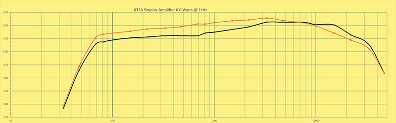
Amplifier performance Volts: Black line - no NFB, Orange line with feedback applied from 8 Ω tap.
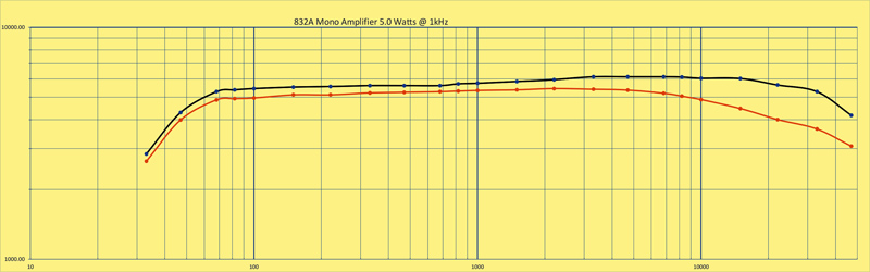
Amplifier performance in mW: Black line - no NFB, Orange line with feedback applied from 16 Ω tap.
The input capacitor was changed from 0.1 μF to 2 μF.
Listening Tests
By definition a listening test is subjective. Room acoustics, loudspeaker and receiver input devices all contribute. In this case the room was the garden office some 7 x 4 metres but filled with bookshelves desks etc. The output device was a Gale book shelf speaker (model unknown). The weakest link was the sensing transducers as the author has hearing loss and is being asked to be bionically enhanced by his wife.
Given the above and a mono sound, suitable signal sources were required. Joan Baez from the early 1960s with a clear pure soprano, Al Bowley from the 1930s and mono recordings from the Beatles and Beach Boys were chosen together with acoustic guitar and piano recordings. Finally some Hammond organ played by Ethel Smith.
The mellow sound rich and with a reserve of power was most pleasing and compared well with the other amplifiers in the room. Certainly worth building as a stereo pair for living room use. For deep base, it would not be a first choice with a bookshelf speaker.
Conclusion
As part of a generation brought up initially with mono recordings this amplifier compares well to the single ended EL84 or ECL86 designs of the day including the author's Grundig TK14 tape recorder.
The 832A or the modern implementation FU-32 perform well as audio amplifiers. Running both sections in parallel with the screen grid connected to a tap on the output transformer should be the best use of the valve.
The present amplifier offering 6.0 Watts output will be a good starting point to a second development of a simplex stereo amplifier with adequate power.
|