|
The author has experimented with audio amplifiers using VHF double tetrodes QQV03-20A and 832A with considerable success. The power is a modest 3-4 Watts from a single valve operated as Class A push-pull but the sound is considered to be excellent for music reproduction in small and medium sized rooms.
This kit was advertised on ebay for a reasonable amount but postage and import duty doubled the price. It gave the opportunity to obtain the valves for the museum FU-32 and two 6J1 pentodes and to compare a commercial single ended implementation with the home-brew versions.
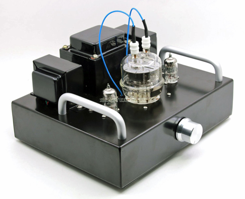 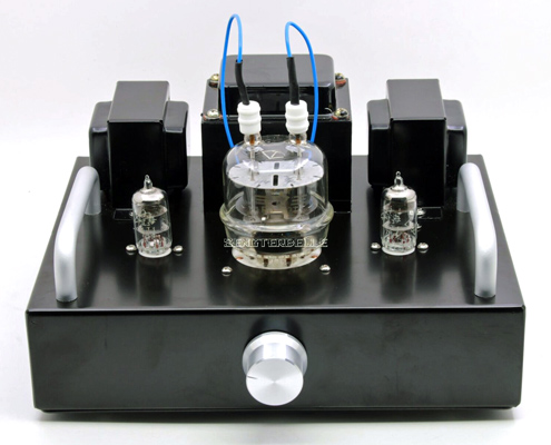 
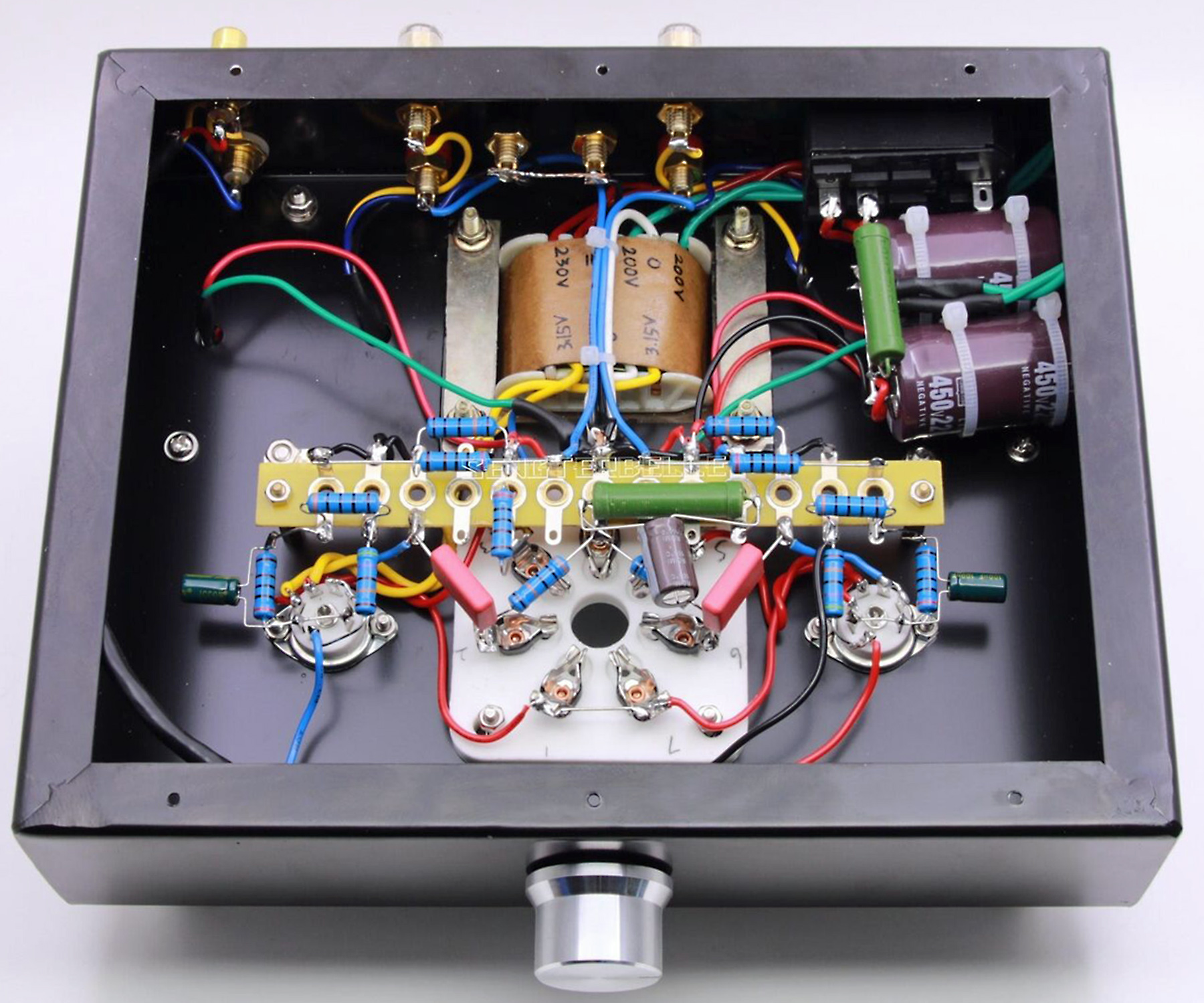
Typical photographs of the completed amplifier as presented in the ebay listings from several suppliers.
The kit arrived very well packed. Unpacking and looking for the instructions revealed just the circuit diagram and a diagram of component positions. As this low power design would appeal to someone new to construction it was considered that a build guide may be useful.
 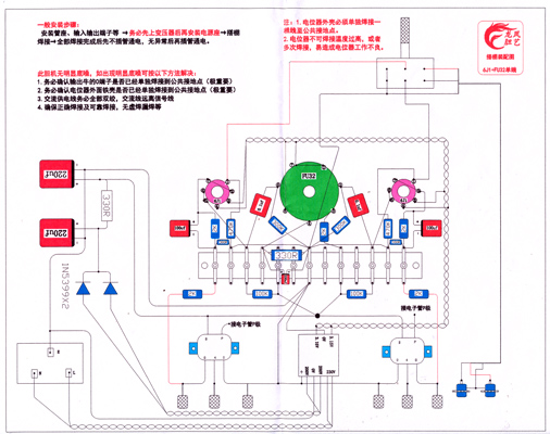
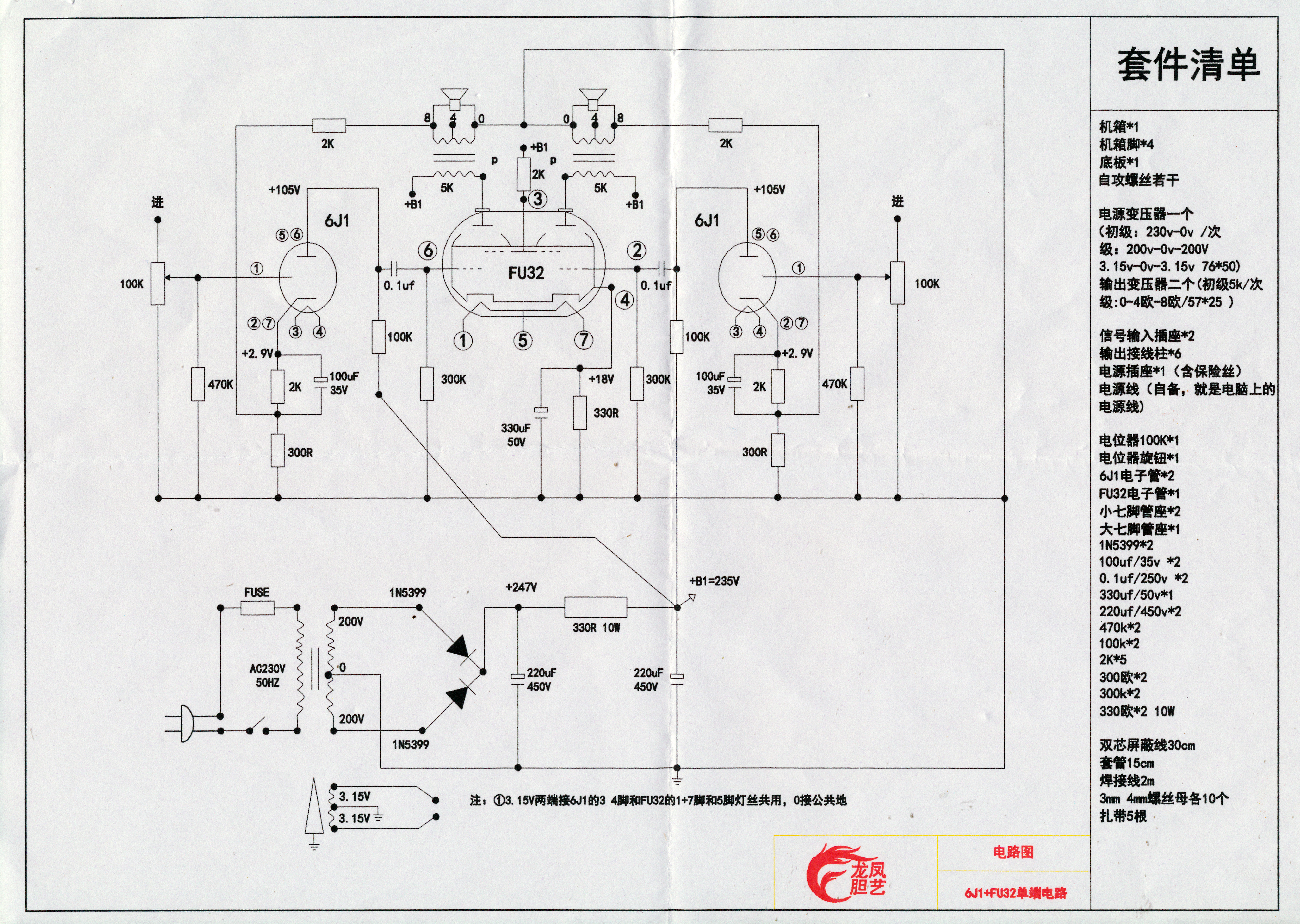
The circuit diagram and component layout.
Fifty years ago the author purchased the Pink Floyd album Ummagumma and the kit photograph below is a homage to the back of cover photograph.
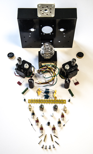
Most of the parts from the kit.
The mains input chassis plug and double pole switch has three connections on the back. The one behind the plug earth pin is the earth. The next is the neutral and the final pin on the outside is the line. Do not fit this connector yet.
The connectors on the back plate were fitted first, starting with the input phono sockets. This allowed a back 12 mm spanner to be inside the chassis while the outer nut was tightened - but not too tight. The speaker wire holes were aligned by inserting a thin rod through the hole and holding the socket in position and then tightening the rear nut with a 10 mm spanner. All eight rear signal sockets mount with insulation between the connector and chassis.
Next the valve sockets were secured. Star washers, not in the kit, were placed between the nut and ceramic B7A socket. The socket has holes for the anode wires to pass through and thus the socket orientation was simple to establish.
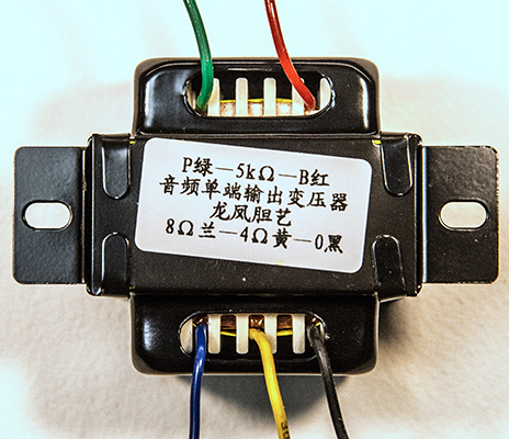
Note the connections to the output transformers.
The transformers are mounted next. Place the wires through the chassis first. Obvious with the mains transformer. Essential with the output transformers. Star washers do prevent the nuts working loose. The heater winding faces the B7A valve holder. With the output transformers the three secondary wires go towards the mains transformer. By following the connections to the colour coded output transformer wires the feedback will be negative as is required and will not produce a howl of positive feedback.
Having secured the transformers, the mains input connector is now fitted. The IEC mains connector was placed such that switching on was a downward motion a European preference. All mains wiring was kept short and placed against the back wall of the chassis and as far away from the input circuits as possible.
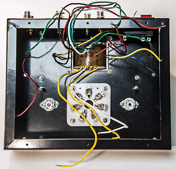
Chassis built ready for wiring-up.
The output sockets were wired next. The thermal mass of the 4mm sockets suggests that a 40 Watt iron is too small but with time a properly wetted joint can be made. The IEC connector was next wired to the transformer primary. The transformer leads being twisted to try an cancel the magnetic field. Whilst the chassis was still open the shielded input cable was soldered to the phono sockets.
Traditional HT capacitors had tag connections with an eye hole to allow the connecting wire to be wrapped prior to soldering thus ensuring a proper mechanical joint as well as an electrical one. Additionally clamps bolted to the chassis would hold the bulky capacitor(s) in place. Modern capacitors of the type supplied are designed for insertion into a PCB that provides electrical and mechanical fixing. The HT supply needs to be safe and so a sub unit built on Veroboard was made. The tracks adjacent to the HT lines were removed where appropriate to ensure good track insulation.
Once built and the HT unit was checked with a low voltage supply to make sure that it was correctly wired. After that test the HT board was installed and tested with the mains connected. An off-load HT of 275 Volts was seen.
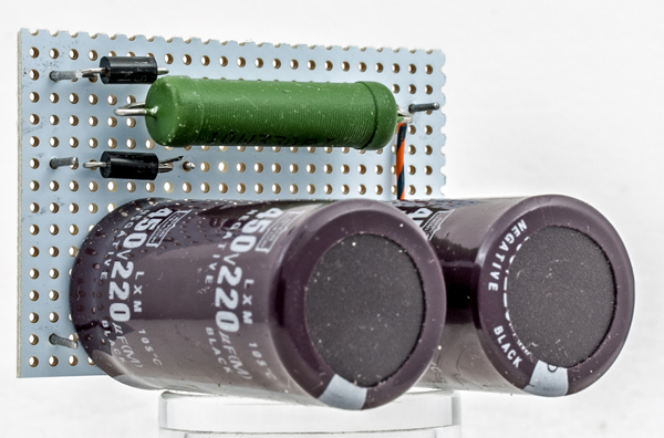
The complete HT rectifier and smoothing board.
Heater wiring is traditionally made of twisted wire to minimise the external magnetic field and placed next to the chassis. This kit has a centre tapped heater winding that further reduces the issue of hum pick-up within the chassis.
The kit is designed for tag construction as can be seen in the top right picture above. However, the author stopped using tag construction in the 1960's when Veroboard became generally available. Also it was recommended back in the day to use VHF practice in construction to minimise pick-up loops and to improve stability. In essence each stage earth is taken to a single point and finally the returns are taken to the input terminal earth connection and all connections are kept as short as possible. The kit is supplied with large resistors but for the low voltage sections modern 0.3 Watt resistors are perfectly adequate in terms of both dissipation and voltage rating. They are also light enough to be supported by a single end if required.
Originally with tag construction the best practice was to make a sound mechanical joint before soldering the joint. With heavy solid carbon resistors of old this was essential due to the weight. In keeping with the spirit of the past and the fact that the valve-holders have fixing eyes most joints were made first by closing the component leads in a loop through the valve-holder eye and crimping with pliers. The component thus remained in place prior to soldering.
Where four components come together in the triode connected input stages the leads are twisted together before being soldered.
To support the HT leads for each channel a small piece of Veroboard was fashioned and fixed to the tag board support pillars. This also allows the voltages to be easily checked.

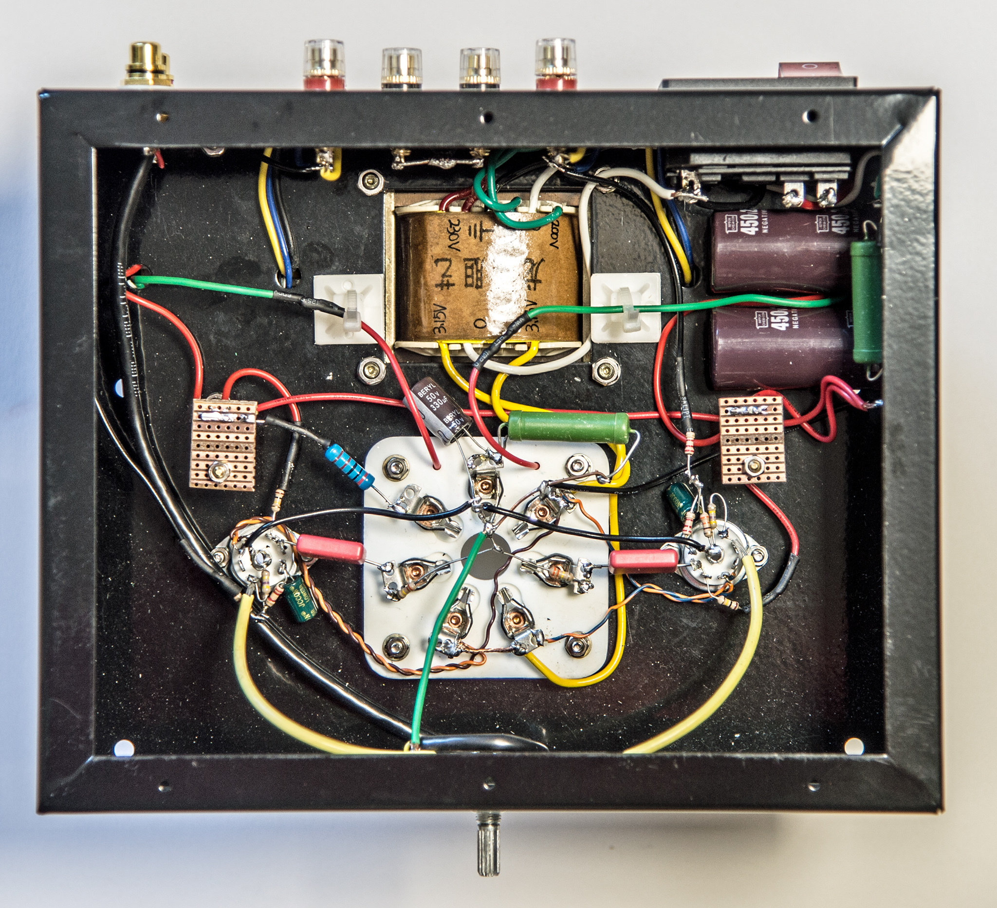
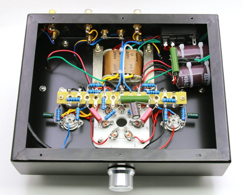
The completed amplifier.
The leads from the volume control to the grids of the input valves are screened and only the end by the potentiometer is earthed.
The kit is supplied with ceramic top cap connectors that have an open tag for the connection. Sleeving is supplied but the author had a number of professional shielded connectors and these were employed for maximum isolation of the HT present above the chassis.
The general rule is that as humans we make mistakes and so a complete check of the wiring was made. With the valve-holders left empty, the HT was applied from a bench supply with a series resistor to prevent damage should a short exist. All was well and the input valves were added. Powering the unit up the heaters came up to temperature and as the valves began to draw current the HT on the anode dropped to 135 Volts. Higher than the 105 Volts specified but the main load on the HT supply was missing.
The input stage was tested with a sine wave to the input socket and the output waveform checked on the oscilloscope. Some second harmonic was present in both the input and output but at around 45 dB below the main signal.
The input amplifier has a measured gain of 21 without distortion.
Time to install the FU32 and the 8 Ohm speakers as a valve amplifier should never be operated without a load. Mains on and mains hum was present but only detectable with ears placed against the speaker. Music input gave a very pleasing sound. The FU32 gets very hot but no sign of overheating after several hours of soak test.
The original tests were made with a pair of Mission two-way reflex bookshelf speakers. Moving the amplifier to the main living room it was connected to a Danish Jamo set-up of two satellite units and a separate bass box. These speakers were purchased in the early 1990's when Jamo were highly regarded (and expensive). The reproduction through the Jamo set-up brought out the bass that had been lacking from the Misions. Subjectively the family found the sound highly appealing. It was a surprise to discover that the sound output filled the room.
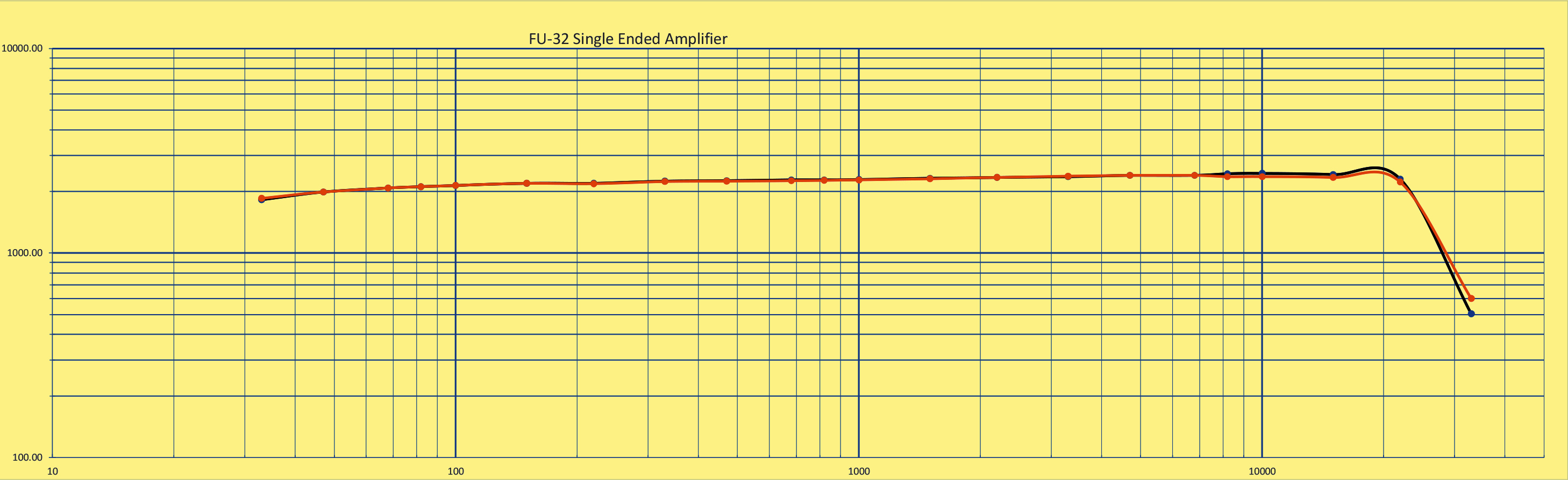
Time for some tests back in the workshop. The function generator was connected to both channels in parallel. Output was to a pair of 8 Ω dummy loads. Both outputs were monitored on the Tektronix 2012 oscilloscope. THD was measured via the FFT function on the 'scope. The results are shown below.
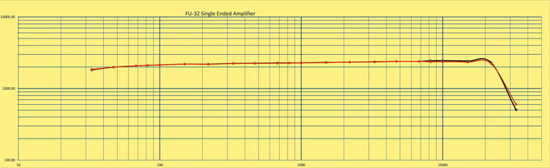
Full power from both channels @ 8% THD. This required 3.3 Volts RMS from the function generator.
The amplifier was giving useful power to over 22 kHz and the power curve shows an almost flat response. The negative feedback is via a single resistor.
Conclusion
With the current feedback arrangement the amplifier produces an acceptable and clean 2 Watts RMS per channel. The ebay advert claims 3.5 + 3.5 Watts but does not specify the level of harmonic distortion at this power or if was measured under pulse conditions. Other ebay suppliers offer amplifiers with both FU32 sections in parallel and give the output as 4 Watts. This seems reasonable.
This entry level amplifier is simple to build and is good value for money. Paying attention to detail and taking time over each stage will produce an amplifier of quality.
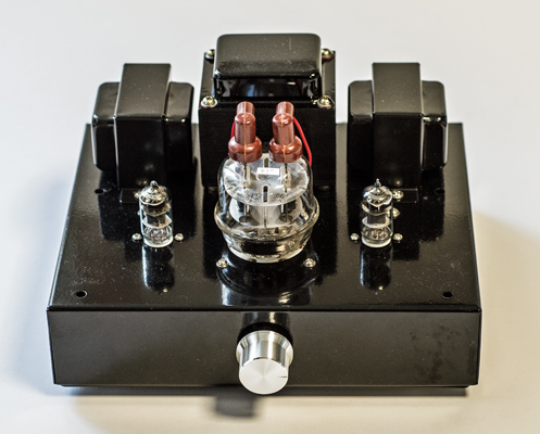
Finished.
|