|
This has been taken from chapter eight. See the extras menu on the right for related articles.
Tungsten Filaments
The thermionic valves that were manufactured for Fleming in 1904, by the Edison Swan Company, had filaments made from carbon. This was a natural choice because, at that time, most electric lamps had carbon filaments and it was the material employed for the modified Edison lamps that Fleming used for his experiments with conductivity in evacuated vessels. As Edison and others had found, however, carbon was not a satisfactory material for lamp filaments. A serious shortcoming was that it readily evaporated at the temperature required for incandescence, blackening the walls of the bulb and leading to a short working life.
A potentially cheaper metal and a superior one to tantalum was tungsten, which had an even higher melting point of about 3,660 K. No furnace could withstand such a high temperature and so, like tantalum, a powdered metallurgy process was required for its preparation.
The first successful use of tungsten as a lamp filament was by the two Austrian engineers, Alexander Just and Franz Hanaman, who patented a manufacturing process in 1904 [1] A Just and F Hanaman, British Patent 23,399 (September 1904), US patent 1,018,502. In this process, an organic binding material was mixed with tungsten powder, giving a paste which was squirted under high pressure through a diamond die to form threads. This was followed by a carbonising process which left filaments of tungsten and carbon. The carbon was then removed by heating the filaments to a high temperature in damp hydrogen. About the same time, an alternative process was developed by the German, Hanz Kugel. In this process, tungsten was produced in a colloidal form, where the metal lacked structure and was finely divided, which simplified the squirting process for forming the filaments.
The tungsten filaments made by these early processes, although capable of producing bright, incandescent light, were very brittle. In 1906, the US company, General Electric, became aware of these European processes for the manufacture of tungsten and the company purchased the patent rights for a total of $1.5M [2] J W Hammond Men and Volts J B Lippincott Co NY 1941, chap 37. By the following year, General Electric introduced their first tungsten lamps, and millions of these were soon produced in spite of their fragility: the prime advantage was an efficiency twice that of tantalum.
The task of producing a viable process for ductile tungsten was given by General Electric to the brilliant engineering scientist William Coolidge, at that time only in his mid-twenties. It took Coolidge six years of painstaking effort to perfect the process. His first laboratory samples of ductile tungsten were made in the autumn of 1908, but it took another four years to develop a satisfactory production process [3] Ibid, pp. 336-39.
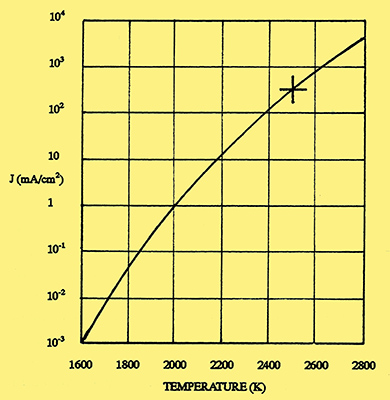
Fig. 1. Emission from a tungsten filament. (Vertical line gives the current density in mA/cm2 and the horizontal line the temperature in Kelvin).
It was natural that the first radio valves to be produced by General Electric should also use tungsten filaments. The construction of these valves was described by Langmuir in a paper read before the Institution of Radio Engineers on 7 April 1915 [4] I Langmuir, 'The Pure Electron Discharge', Proc IRE, 3, September 1915, pp 261-93. In this paper, he showed how the emission from a tungsten filament varied with temperature. This relationship, taken from more recent data, is shown in Fig 1, where each successive vertical division represents a ten-fold increase of emission current. Below a temperature of 2,100 K, the emission (measured in milliamperes per square centimetre of filament surface area) is negligible, but then increases rapidly until at its normal operating temperature of 2,500 K, the emission is 300mA/cm2. To show how sensitive the emission is to changes of temperature, a decrease of 100 degrees will cause the emission to fall by a factor of three.
Gradual evaporation of the tungsten occurs at the operating temperature, even though this is some 1,000 degrees below the melting point. The evaporation leads to a thinning of the filament which eventually results either in a fracture or a burn-out. In practice, a life in excess of 1,500 hours can be expected from low power valves using such filaments, provided they are not over- run. For example, a 10% increase in operating voltage will shorten the life by a factor of four. Conversely, a reduction of filament voltage will increase the life. (In the early days of radio, when bright emitter valves were in common use, it was normal practice to connect a rheostat in series with the battery supply to the filament to reduce the current when reception conditions were favourable.)
Thoriated Tungsten Filaments
During his experiments with tungsten, Coolidge found that the material could be made more ductile if a small quantity of thoria (thorium oxide) was added during the manufacturing process. Langmuir discovered that some of the filaments made from this material produced copious emission at considerably lower temperatures than pure tungsten, and found this was due to the formation of a monatomic layer of thorium at the surface of the tungsten. From this work, Langmuir developed a heat treating process for the manufacture of thoriated tungsten filaments. These filaments produced a similar emission to untreated tungsten, but at a much reduced operating temperature.
The heat treating process for thoriated tungsten filaments, which was generally adopted throughout the valve manufacturing industry from about 1922, consisted of two stages. The first was to flash the filament at a temperature of about 2.800 K for a minute or so during the pumping process. The second was the activation stage when the filament was maintained at a reduced temperature of about 2,100 K for several minutes. At periodic intervals during this stage, the temperature was lowered to about 1,500 K and the emission measured. When the emission became steady, the activation process was stopped and the valve sealed ofi from the pumps. For normal operation, the filament temperature was typically 1,800-1,900 K, at which it glowed red rather than the white of a comparable untreated tungsten filament.
During the high temperature flash phase, the thoria breaks down into pure thorium and oxygen, both of which are liberated from the surface of the tungsten. During the activation stage, the process of dissociation slows down; the more active oxygen continues to evaporate, whilst the thorium spreads over the surface to form a monatomic layer which bonds closely to the tungsten atoms, and further thorium evaporates from the surface. When the filament is lowered to the operating temperature, a balance occurs between the slow evaporation of thorium from the surface and its replenishment from the dissociation of thoria within the bulk tungsten.
A major problem which prevented the early commercial exploitation of thoriated tungsten filaments was that the monatomic thorium layer was readily attacked by the traces of oxygen within the evacuated bulb to form thorium oxide. At the time, it was not possible to maintain a sufficiently high vacuum to prevent this 'poisoningb action and the consequent loss of emission. The problem was eventually overcome in the early 1920s by a combination of high temperature out-gassing and the use of a metal getter to adsorb free gas molecules.
The life of the thoriated tungsten filament can be considerably improved by a carbonising process. Prior to flashing, the filament is heated in a hydrocarbon vapour at a temperature of typically 1,600 K, which produces a layer of tungsten carbide at the surface. After flashing and activation, the thorium adheres to the tungsten carbide and a stronger bond is formed than with pure tungsten. A further benefit of the carbonising process is to improve the resistance of the thorium to bombardment by positively charged gas ions.
Oxide-Coated Cathode
The origin of the oxide-coated cathode can be traced back to 1903 when, by a chance discovery, Arthur Wehnelt noticed that a platinum filament, which had been contaminated by grease, gave a strong electron emission at a temperature of about 1,200 K, well below that required for uncontaminated platinum. Wehnelt correctly deduced that impurities within the grease were responsible for the enhanced emission. As a result of this discovery, Wehnelt carried out a series of experiments which showed that filaments coated with the oxides of alkaline earth metals, such as calcium and barium, would give an equivalent emission to an uncoated filament, but at a considerably lower temperature.
Following this pioneering work of Wehnelt, the oxide-coated cathode was used in several types of very early valves, such as those of von Lieben and Round. The oxide-coated cathode was also employed by Western Electric for the amplifier valves used in their telephone and telegraph circuits from about 1913. Apart from the valves of Western Electric, however, the oxide-coated cathode was soon displaced by the tungsten filament because of the difficulty in manufacturing reliable coated cathodes with an acceptable life. Nevertheless, much experimental work continued and gradually the manufacturing and reliability problems were overcome. The first British valves to use these improved cathodes were introduced from 1924.
Before describing the later processes for the manufacture of oxide-coated cathodes, some of the earlier processes will be outlined. In these earlier processes, the coating was usually barium oxide and four methods of manufacture were used [5] B Hodgson and L S Hartley, 'The Development of the Oxide-Coated Filament', JIEE 77, 1929, pp 762-71.: briefly, these were by melting, evaporation, deposition and pasting. Since pasting was the forerunner of the later processes, this will be discussed separately.
In the melting method, the core material used for the filament was typically nickel or platinum, although nickel was preferred because of the high cost of platinum. The coating was carried out by drawing the wire through a bath of barium nitrate and the oxide was formed by heating the wire to a temperature of about 1,200 K during the vacuum pumping process. The disadvantage of this technique was that the final oxide coating had poor adhesion.
In the evaporation method, the wire was repeatedly dipped in a barium salt solution and between each dip, the filament was heated in carbon dioxide. As a result, a layer of barium carbonate was gradually formed. The carbonate was then converted to barium oxide by heating the wire in vacua at a temperature of about 1,250 K.
With the deposition method, the filament - typically nickel or tungsten - was first oxidised (or, alternatively, a thin layer of copper was deposited on the tungsten which was then oxidised). One of two methods was then used to produce the required barium oxide coating: the first was by vaporising pure barium from a source close to the anode and the second was to coat the anode with barium azide and reduce this to barium and nitrogen by heating the anode. In both methods the vaporised barium combined with the nickel, tungsten or copper oxide to form a coating of barium oxide on the filament. Both these methods were carried out during vacuum pumping. With this vapour process, barium was also deposited as a mirror onto the glass surface of the bulb and this then acted as a getter to adsorb unwanted gas molecules after the final seal had been made. The various manufacturing processes were described in a series of Philips patents of 1923/24 [6] N V Philips Gloelamfabrieken, British patents 209,730 (Convention date, Holland, 12 January 1924); 229,622 (Convention date 18 February 1924); 245,145 and 245,146 (Convention date 24 December 1924); 245,147 (Convention date 27 December 1924)..
Ideally the oxide coating should be a layer of uniform thickness, well bonded to the core material and composed of very small particles. The minimum thickness should be 0.1 micron (10-7m), which is about 400 atom layers, although in practice a much thicker layer was used. The previous coating processes described were in general not satisfactory: they were slow and did not produce consistent material which was essential for low cost, high volume manufacture. As a result, they gave way to the pasting and spraying processes which were derived from the methods used by Western Electric [7] H D Arnold, 'Phenomena in oxide-coated filament electron tubesb, Phys. Rev., 16, Series 2 1920, pp. 70-82. [8] Western Electric Co. Ltd., British patent 180,090, App. 28 February 1921, Iss. 25 May 1922..
A brief description will be given of the Western Electric process because of its historical importance. The filament was made from an alloy of platinum combined with 6% iridium which was rolled to form a ribbon 0.3 mm wide and 0.05 mm thick. The wire was successively coated with four layers of barium carbonate followed by four layers of strontium carbonate. The process was repeated to give a total of sixteen layers. The barium and strontium carbonates were suspended in a waxy material, such as paraffin, to form rods, and applied by pasting. As each layer was applied, the filament was momentarily heated to a temperature of about 1,300 K to drive off the paraffin. When all the coats had been applied, the filament was heated to about 1,500 K for two hours, which reduced the carbonates to barium and strontium oxides. According to Arnold, Western Electric manufactured half a million valves during World War 1 using oxide-coated filaments prepared in this way.
Consideration will now be given to the manufacturing methods that were used in Britain. These may be broken down as follows:
- Manufacture of the core material (filament for the directly heated cathode and sleeve for the indirectly heated cathode).
- Preparation of the emission paste that forms the oxide coating.
- Deposition of the emission paste onto the core material.
- For the indirectly heated cathode, manufacture of the heater and its assembly into the cathode sleeve.
- Decomposition of the emission paste to the oxide coating.
- Activation of the cathode to achieve full and constant emission.
Each of these stages will be dealt with in brief detail. For more comprehensive information, the reader should refer to the references [9] G Herrmann and S Wagener, The Oxide-Coated Cathode. Volume 1 - Manufacture (Chapman & Hall Ltd., London, 1951). [10] M Benjamin, C W Cosgrove and G W Warren, 'Modern Receiving Valves: Design and Manufactureb, Proc. IEE, 80, 1937, pp. 401-39 (see pp. 416-21). [11] S R Mullard, 'The Development of the Receiving Valveb, JIEE, 76, 1935, pp. 10-16..
Core Materials
The metal used for the core material must meet several stringent and conflicting demands. Amongst the most important of these are a high melting point, together with low evaporation at the temperatures required for manufacture and subsequent operation; high tensile strength and low re-crystallisation at the operational temperature; negligible chemical reaction with the oxide coating and gases or vapours present; ease of de-gassing and good heat economy.
Very few metals meet these demands. For directly heated cathodes, the filaments were usually made from tungsten or a nickel alloy. For indirectly heated cathodes, either nickel or nickel alloys were used because they were easy to form into shape, either by extruding or bending from sheet.
Preparation of the Emission Paste
The emission paste was made by mixing a suspension of alkaline earth compounds either in an organic liquid or with water which contained an organic binder. In the early years the paste was made using alkaline earth oxides, such as barium oxide, but this proved unsatisfactory because the oxides were readily converted to hydroxides or carbonates by the presence of air or carbon dioxide. These unwanted compounds weakened the bond between the coating and the metal core which caused the coating to flake off. An alternative was to use carbonates of the alkaline earth metals. These had the advantage that they could be reduced to the oxides by heat treatment under vacuum conditions, during the pumping phase, when they were safe from the harmful effects of reactive gases. Initially, barium carbonate was used on its own, but it was soon found that a mixture of barium carbonate and strontium carbonate gave both a better bond to the metal core and improved emission, with the emission peaking when the mixture was approximately equi-molecular. Fig. 2.
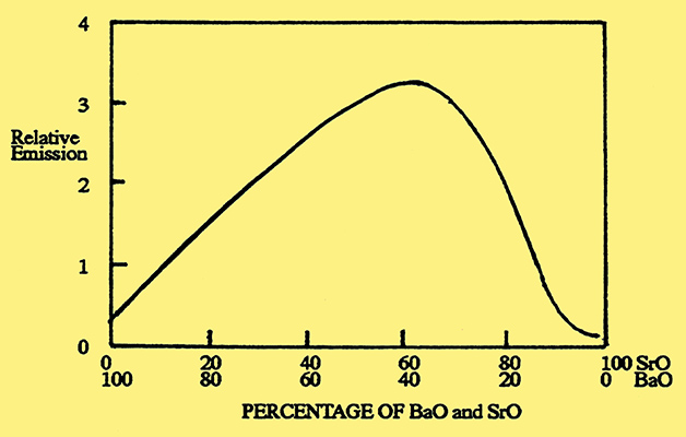
Fig. 2. Emission from an oxide-coated cathode as a function of the barium oxide and strontium oxide content.
Deposition of the Emission Paste
Several methods have been used for deposition of the emission paste onto the core material. For directly heated cathodes, the three most commonly used were painting, dipping and dragging. With the painting and dipping methods, the coating was built up in small layers, each layer being dried, usually at a high temperature, before a new layer was added. These two deposition methods were slow and not suited to high volume or low-cost manufacture. Consequently they were superseded by the dragging method, whereby the filament was pulled through the paste, which was held in a suitable container, and then through a drying furnace. Again, the required thickness was built up by continually repeating the process. The process was capable of producing up to 100 metres per hour of coated wire of uniform thickness [12] Herrmann and Wagener, op. cit., p. 35.. The final coating thickness ranged typically from 20 to 80 microns (0.2 to 0.8 mm). For a 2 V directly heated filament, the overall thickness of the coated wire was about 85 microns. With the introduction of the 1.4 V, 50 mA series of battery operated valves in 1939, a much thinner coated filament was required. For example, the Philips valves used a wire diameter of 10 microns with a coating thickness also of 10 microns, making an overall thickness of 30 microns. With such fine wire, it was necessary, for strength reasons, to change from nickel to tungsten. For the coating of these filaments, Philips changed to a cataphoretic process, where the barium particles were given a negative charge and were drawn towards the filament which was positively charged.
A fourth deposition method, and one particularly suited to indirectly heated cathodes, was to spray the core material with the paste. In order to ensure a uniform coverage, a series of strategically placed nozzles were employed, similar to that used in automated paint spraying plants.
Manufacture of the Heater
For indirectly heated cathodes, there are four important requirements for the heater-cathode combination: robust heater, high resistance electrical insulation, good thermal conductivity to ensure a rapid warm-up of the cathode, and a very low electro-magnetic field from the alternating current flowing through the heater.
The operating temperature required for the heater is typically 1,400 K, which demands that the core material used for the heater must have a high melting point. Tungsten has this property, but in its pure form, it is prone to re-crystallisation after prolonged exposure at the operating temperature, resulting in brittleness and possible fracture of the wire. Various ways have been devised to overcome this problem. One was to add a small quantity of alumina to the tungsten, typically 0.02%. An alternative was to make the heater from a tungsten-molybdenum alloy, which had the advantage of a high melting point combined with the good ductability of molybdenum.
Early cathodes, such as those of Freeman and Wade, used a twin-bore insulated sleeve into which a simple V-shaped tungsten filament was inserted. The insulation material frequently used for this was magnesia. This arrangement was far from satisfactory owing to the poor thermal conduction between the heater and cathode sleeve. An important improvement was developed by E Y Robinson in 1926 with the invention of the slip-coating technique, whereby the tungsten filament was coated with kaolin. This coating gave an increased insulation resistance and also provided superior thermal conduction to the cathode sleeve.
In time, the preferred material used to coat the heater was alumina as this was found to give superior insulation resistance and also provided a good bond to the core material. It was found that good insulation could only be achieved if all the impurities were removed from the alumina, the most troublesome of these being sodium aluminate. It was also found that the insulation resistance could be considerably improved if 1-2% of beryllia was added to the alumina [13] Benjamin, et. al., op. cit,. p. 420..
Although the V-shaped heater was simple to produce, it did not always provide adequate cancellation of the alternating electro-magnetic field. A better construction was to form the heater into a non-inductively wound reverse helix or reverse double helix. Improved heat distribution could be achieved by using a variable pitch to the helix. Two types of heater are shown in Fig. 3. In both examples the fine wire is first wound into a tight helix and then bent into the shapes illustrated. Finally the bent wire is then compressed and pushed into the heater sleeve.
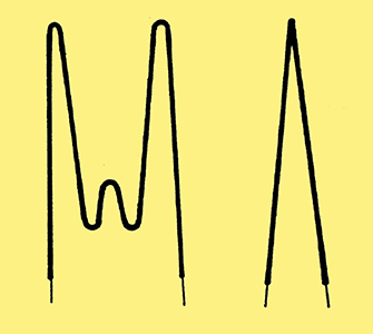
Fig. 3. Two common forms of helically wound heaters.
To return now to the alumina coating. For the simple V-shaped construction, drag coating was frequently used, and for the more complex helix or double-helix construction the spray method of coating was preferred. After the coating was applied, by whichever method, the heater was fired in hydrogen at a temperature of 1,800 K to 2,000 K, which sintered the alumina onto the core material.
Decomposition and Activation
Decomposition of the alkaline earth carbonates into the required oxides takes place after the electrodes have been assembled and mounted inside the bulb. First the assembled valve is placed on the pump, and during the pumping process, the electrodes and glass bulb are de-gassed by raising them to a high temperature, whilst at the same time the metal parts are heated by induced RF currents. Following the de-gassing process, and when the gas pressure has been reduced to 10-2 Torr or less, the cathode is steadily raised to a temperature of about 1,150 K for a few minutes, which causes the carbonates to decompose and form the oxides. The optimum time required for decomposition depends upon the type and size of cathode, the cathode temperature and the gas pressure.
The oxide-coated cathode is an n-type semi-conductor and the emission depends upon the presence of free barium metal within the coating. This metal is released partly during the decomposition process, but mainly during the activation process that follows. Activation takes place after pumping has been completed, the getter fired and the valve finally sealed.
The process entails heating the cathode to a temperature of between 1,275 K and 1,475 K for a time that may range from a few minutes up to an hour, depending upon the type of cathode and the temperature used. Periodically during this process, the cathode temperature is lowered to its operational level and the emission checked. Activation is completed when the required emission current has been achieved.
Comparison of Cathodes
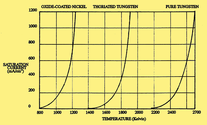
Fig. 4. Saturation current from three types of cathode.
Fig. 4. shows how the saturation currents for the three types of cathode vary with temperature. The shapes of the three curves are almost identical, the only significant difference being their relative position along the temperature axis. Typical performance figures for the cathodes are given in the table below.
| Type of Cathode | Operating Temp. (K) | Emission Density mA/cm2 | Efficiency mA/W | Tungsten | 2,500 | 250 | 3.5 | Thoriated Tungsten | 1,875 | 1,500 | 60 | Oxide-coated nickel (DH) | 1,000 | 100 | 50 | Oxide-coated nickel (DH) | 1,200 | 1,000 | 250 | Oxide-coated nickel (IH) | 1,000 | 100 | 20 |
The data given for the emission density and emission efficiency are typical values and these are very temperature dependent; also, for the oxide-coated cathode, these values depend upon the composition of the oxide and the particle size.
As the electrons are emitted from the cathode and attracted towards the anode, they may strike gas molecules and dislodge electrons from their outer shell to give positive charged particles, which are then attracted towards the cathode. The velocity of these particles increases as the anode voltage is increased, and for high anode voltages, they will strike the cathode with considerable force. With the oxide-coated cathode it is necessary to restrict the anode voltage to less than about 2 kV, as otherwise severe damage could be caused to the oxide coating. The thoriated tungsten cathode is more robust and the thorium layer is reasonably safe to anode voltages up to about 5 kV. For voltages in excess of 5 kV, it is necessary to use pure tungsten filaments.
The life of the tungsten filament is typically 1,500 hours. Because of the high operating temperature, there is a constant evaporation of the tungsten and also a process of re-crystallisation, which results in brittleness. Both these factors are likely to cause fracture of the filament. Although the thoriated tungsten filament operates at a lower temperature, its life is also restricted to about 1,500 hours because of evaporation of the thorium, which results in loss of emission. A further problem is that the filament is often very thin and hence liable to be fragile. Conversely the life of the oxide-coated cathode may be many thousands of hours because of its comparatively low operating temperature.
Typical Filament Assemblies
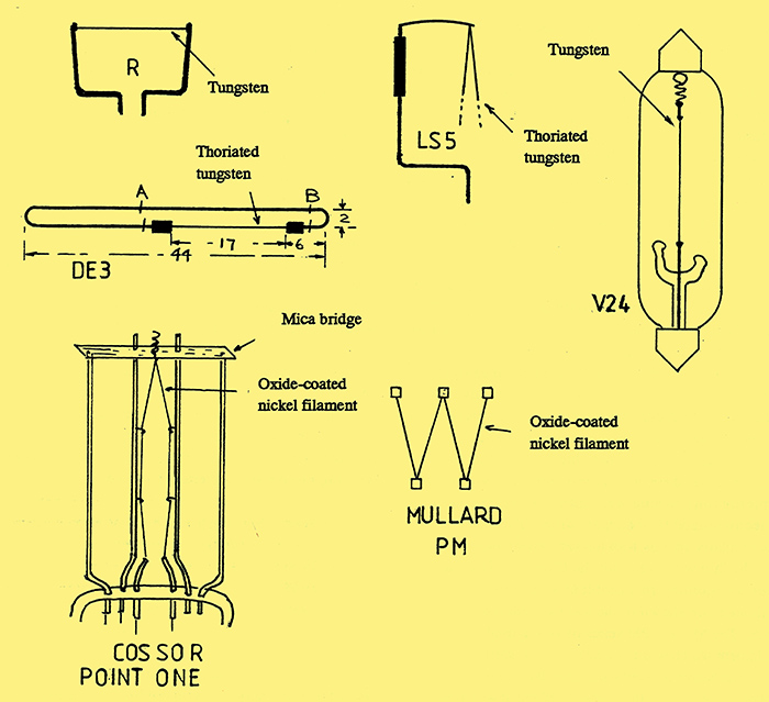
Fig. 5. A selection of valve filaments.
Fig. 5 shows several examples of valve filaments. Early, low power, bright emitter valves such as the R and V24, used straight tungsten wire under spring tension to prevent sagging when heated to its operating temperature. With the R-valve, the filament was held under tension by fork-like support wires, whereas the V24 had a small spring at one end. The LS5 output valve had a V-shaped thoriated tungsten filament, which was held at the top by a sprung wire cantilever.
The fourth diagram in fig. 5 shows an example of a low power thoriated tungsten filament, rated at 60 mA, and used with the Marconi-Osram type DE3. The filament was made of very fine wire held in a hair-pin construction made of hard drawn nickel, an arrangement which allowed the filament to be welded to its support wires prior to assembly in the valve. After assembly, the nickel wires were, in turn, welded to the internal supports and then cut at points A and B.
A major problem that plagued both the thoriated tungsten and oxide-coated tungsten valves was microphony, which was caused by vibration of the electrodes and their support wires. This problem was particularly serious with the low-power valves because of the thin wires used for the filament. Two methods for overcoming this problem with the oxide-coated filament are shown in the last two diagrams in Fig. 5. The Mullard PM series of valves used a W-shaped filament which was suspended by five spring hooks. In an alternative arrangement used by Cossor with their 'Point One' series, the V-shaped filament was supported in seven places: at the top, the bent wire passed through a mica bridge and was held under tension by a spring.
References
- A Just and F Hanaman, British Patent 23,399 (September 1904), US patent 1,018,502
- J W Hammond Men and Volts J B Lippincott Co NY 1941, chap 37
- Ibid, pp. 336-39
- I Langmuir, 'The Pure Electron Discharge', Proc IRE, 3, September 1915, pp 261-93
- B Hodgson and L S Hartley, 'The Development of the Oxide-Coated Filament', JIEE 77, 1929, pp 762-71.
- N V Philips Gloelamfabrieken, British patents 209,730 (Convention date, Holland, 12 January 1924); 229,622 (Convention date 18 February 1924); 245,145 and 245,146 (Convention date 24 December 1924); 245,147 (Convention date 27 December 1924).
- H D Arnold, 'Phenomena in oxide-coated filament electron tubesb, Phys. Rev., 16, Series 2 1920, pp. 70-82.
- Western Electric Co. Ltd., British patent 180,090, App. 28 February 1921, Iss. 25 May 1922.
- G Herrmann and S Wagener, The Oxide-Coated Cathode. Volume 1 - Manufacture (Chapman & Hall Ltd., London, 1951).
- M Benjamin, C W Cosgrove and G W Warren, 'Modern Receiving Valves: Design and Manufactureb, Proc. IEE, 80, 1937, pp. 401-39 (see pp. 416-21).
- S R Mullard, 'The Development of the Receiving Valveb, JIEE, 76, 1935, pp. 10-16.
- Herrmann and Wagener, op. cit., p. 35.
- Benjamin, et. al., op. cit,. p. 420.
|