|
The Cossor Kalenised Filament
Following the not very successful oxide coated filament of the Wuncell range, Cossor produced a new oxide coated filament in late 1926. The trade name of this filament was Kalenised and there appears to be no evidence for what this technique really was. The following has been taken from a 1927 article.
The Kalenised filament in the new Cossor valve differs from others because the vital emission which is essential for the efficient working of the valve proceeds not from the core, but from the Kalenised layers surrounding it.
The metal core serves merely to carry the trifling current required to liberate the flood of electrons. The Kalenised with its large diameter, greatly increases the total emission service.
With the tremendous electron flow afforded by the Cosser valve, a much greater degree of control in dealing adequately with both the minute and powerful currents which a receiving set resolves into audible sounds.
Cossor also were proud of the fact that their new filament could withstand a considerable fall without breaking. In plain language it seems that Cossor were distancing themselves from both fragile tungsten wire and the bright glow of thoriated tungsten filaments by saying that the new filament produced hardly any glow. It is possible to see this new filament as a nickel core (ductile) with several layers of oxide coating added. The early oxide coating was probably added as a single thick layer.
The Kalenised filament was superseded in September 1929 when the 'New Process' range was unveiled.
The Cossor Point One Valves
Cossor's naming system at the time had the first digit as the filament nominal voltage and the second two digits indicating the filament consumption. So 210 was a two Volt 0.1 Amp filament. The letters indicated function. But in 1926 the valves did not carry the Type designation on them.
Initially the new valve range featuring this Kalenised filament was for use with a 2.0 Volt accumulator and the filament rating was printed as 1.8 Volts. The first two introduced at launch in 1926 were a red top for HF amplification or Resistance Capacity coupled use (210H) and a plain top for detector and AF amplification (210D).
An interesting point concerning these valves from 1926-7 is that the black plastic base has a sharp transition between two diameters close to the pins and this feature is a good indication as to date produced. Later revised specification types had a curved transition between these two diameters. See Point One HF and 210HL for examples.
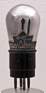
Early in 1927 the red top was re-branded as the 210HF and featured a red paper band carrying the identification. The detector became the 210D with a black paper band. The paper band carried the wording Point One Det & LF not the 210D Type designation. The 210RC was introduced at the same time with the label saying Point One Specially Designed for Resistance & Capacity Coupling.
Also in 1927 the triode range was extended to include both four Volt and 6 Volt filament versions of the two Volt types. 410HF & Det, 410LF and 410RC. 610HF & Det, 610LF and 610RC. The four Volt type 410HF followed in 1928.
The Cossor Screened Grid (SG) valve appeared in September 1927 and they introduced the SG210, SG220, SG410 and SG610 that year. The SG210 did not carry the Point One wording but the Type designation S.G.210.
All of the signal triode valves in the Point One series were built with a development of the original hat shaped anode. This was larger than that used for the bright emitters P1 and P2 and was made from two plates shaped and welded together. The main fixing struts were incorporated between the plates at the sides. At the top was included an insulator to hold the point of the inverted V filament. See Point One RC for a picture.
The Cossor Stentor Valves
To complement the low level signal valves, Cossor introduced audio output valves under the Stentor name. The first was the Stentor Two released in late 1926. The colour code for the Stentor range was a green paper band.
The two and four Volt filament versions used the pointed anode of the Point One range but the six Volt type required a longer filament and a double inverted V was used. This needed a new anode shape. This was intermediate between the pointed anode and the later box anode and featured two filament support springs at the top of the anode. One of our Point One RC valves has this configuration. and the advert from May 25, 1927 has diagrams of both anode shapes.
See Stentor Two and Stentor Four
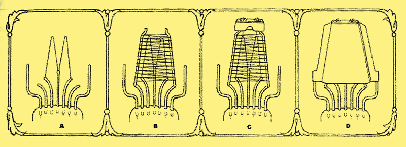
The construction of the electrodes for the six Volt Kalenised filament valves. c. shows the filament tension springs.
References
- British Radio Valves 1926-19461043, K R Thrower
- Cossor adverts
- Paperspast.natlib.govt.nz Some aids to clear reception 1927
|