|
Throughout the history of thermionic valve manufacture there has been considerable impetus to develop improved cathodes, as it is the cathode that chiefly dictates a valves power handling capacity and efficiency.
Since the rise of semiconductors, thermionic cathodes have been relegated to a few specialised areas such as cathode ray tubes (CRT), high power microwave frequency circuits and high end audio amplifiers but much of the early development of electronics was intimately bound to cathode technology. After being sidelined for several decades, cathodes have again come to prominence with the accelerating development of cold field emission technology.
During the valve era extensive research was dedicated to devising cathodes with lower operating temperatures while maintaining or increasing their electron emissions. High cathode temperatures bring several drawbacks. One index of merit of a thermionic cathode is high emission current to required heating power ratio, which is a function of emissions per unit area, and operating temperature (Fig. 1 & 2).
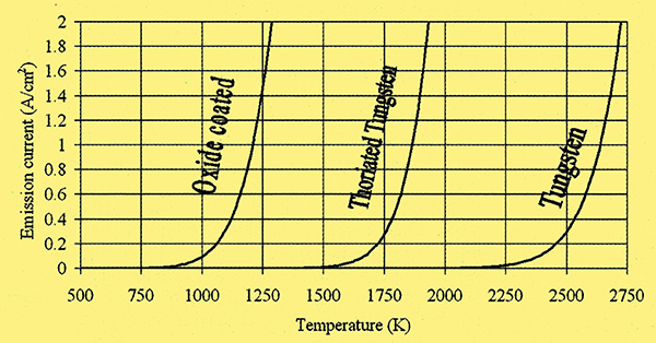
Fig.1. Plots of emission current per cm2 against temperature for the three main thermionic cathode types.
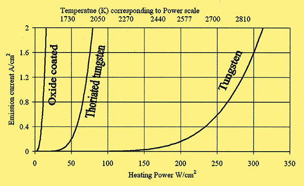
Fig. 2. Emission per Watt of heating current for three thermionic cathode types.
This is far lower for cathode types with cooler operating temperatures. High temperature filaments have a limited life because of increased vaporisation of atoms from their surface, and impose considerable constraints on the design of cathodes and their surrounding elements, requiring wide spacing to control the temperature of close electrodes [1] Fred Rosebury, Handbook of electron tube and vacuum techniques. ISBN 1563961210. A wide gap between anode and cathode means that a large anode voltage is necessary to create the necessary field in the immediate vicinity of the cathode to draw away the cloud of emitted electrons. Fig. 4.
These electrons are then considerably accelerated as they pass to the anode. The energy they thus acquire is transferred to the anode on impact, heating it. Consequently high power valves often have hotter anodes than cathodes! The dividends from reducing cathode temperature are substantial.
The history of thermionic cathodes can be conveniently divided into two phases. From the discovery of thermionic emission in the 1870s until around 1912, thermionic devices were one class of many under investigation by scientists and engineers but did not show outstanding potential. During this period development was driven by curiosity and isolated individuals and was consequently haphazard. This situation then changed to one where thermionic devices assumed great economic importance.
Up to 1912 - scientific curiosity
The British physicist Frederick Guthrie advanced his theory of thermionic emission in 1873 following a series of experiments on hot charged bodies. When he placed a red-hot negatively charged metal sphere in a vacuum it discharged but a positively charged sphere did not. He thus concluded that hot metal bodies emit negatively charged particles. His hot spheres were the first thermionic emitters.
In the 1880s, three researchers: Goldstein, Hittorf, and Edison independently found that a current would flow between the heated filament of an incandescent light bulb and an extra electrode placed in the bulb. The light bulbs of the time (Swan and Edison types) used carbon filaments which formed the first thermionic filament cathodes. The first public description and demonstration of the effect was given on behalf of Edison by Edwin Houston in 1884 at the Philadelphia International Electrical Exhibition. William Preece, chief engineer of the British Post Office was present. He approached Edison for some sample valves and was generously given several. On his return to England he conducted a series of experiments into the phenomenon and published his results in 1885. He used the term 'Edison effect' for the current flow between the filament and electrode in his paper and the name stuck. The nature of the current was not understood at the time. The discovery had been made in the course of investigating the blackening of bulbs due to the evaporation of carbon from the filament and condensation on the inside of the bulb. Early theories thus involved charged carbon vapour as the current carrier.
In 1897 J J Thompson measured the charge to mass ratio of electrons establishing that they have negative charge and mass. Electrons then became leading contenders for the thermionic charge carrier. Early valves had modest degrees of vacuum and ionised gas molecules as well as electrons carried appreciable current. Later when valves with high or hard vacuums were produced electrons carried effectively all of the current.
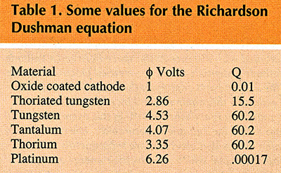
A major early contribution was made by Owen Richardson who studied the behaviour of hot metal filaments in gases and vacuum. He published on the platinum filament in 1901 and further results from platinum as well as carbon and sodium in 1903. He formulated an equation to model the emission current per unit area: i = QT-e(-Φε/kT) A/m2. A more accurate equation was provided by Saul Dushman from a quantum based derivation in 1920:
i = QT2-e(-Φε/kT)
where i = saturation emission current from a hot cathode in A/m2
ε = the electronic charge (1.6022 × 10⁻¹⁹ coulombs)
k = Boltzmans constant (1.3807 × 10⁻²³ J/K)
T = Kelvin temperature
Φ = the work function of the cathode surface (see table 1)
Q = a constant specific to the cathode surface (see table 1).
This is now know as the Richardson Dushman equation.
In this period cathodes were directly heated filaments first made of carbon and then platinum, tantalum or tungsten and operated at around 2,500 to 3,000K. Tantalum was in use until around 1913 as a filament material but it tended to warp in service. It was replaced by tungsten but tungsten has lower emission than tantalum. Filaments made from tungsten wire with tantalum wrap known as Hudson filaments were briefly popular as was tungsten coated in a tantalum paste.
Such cathodes were superseded for most applications by thoriated tungsten in the 1920s and oxide cathodes in the late 1920s and 1930s. This chronology reflects the manufacturing difficulties associated with the types rather than the sequence of their discovery [3] History of Thermionic devices. Conference proceedings of the Newcomen Society, 23/4/1994, ISBN:0-904685-05-5.
Oxide cathodes that were later to dominate the field originated serendipitously in the pre 1912 period. The German scientist Arthur Wehnelt, while working with platinum wire heated to comparatively modest temperatures in gases, noted luminous spots on the wire. He traced this to contaminants deposited on the surface of the wires during preparation that gave localised areas of high electron emission, exciting gas molecules that emitted light on relaxation. This led to a series of experiments on oxide-coated cathodes, the results being published from 1903-1905.
Histories of the valve highlight de Forest, Fleming, and Langmuir; Wehnelt usually gets less attention. He has nevertheless a persuasive claim to each of the three main developments in valve technology. He used his alkali earth oxide coated cathode to make a diode valve that predated Flemings (detailed in a 1906 patent application). It was for charging accumulators for x-ray equipment and was not applied to radio reception and so was of little interest to radio historians. He invented a telephone repeater (amplifier) that worked by using a variable electric field to deflect a cathode ray on and off a target thus varying the cathode current. This predated de Forest's Audion (the first triode) and was conceived and designed for, built for and apparently fulfilled the purpose. Compare this with de Forests triode which he happened on as one of numerous devices he investigated. He did not perform a detailed and accurate characterisation of its behaviour and exploited it after its potential had been recognised by others. Finally Wehnelts oxide cathode predated the thoriated cathode by at least 10 years [3] History of Thermionic devices. Conference proceedings of the Newcomen Society, 23/4/1994, ISBN:0-904685-05-5.
1912 on - commercial development
Although de Forest introduced his Audion triode in 1906, its potential as an amplifier was not appreciated at first. An urgent need for a means of amplification had meanwhile arisen from the demands of long distance telephone and radio communications. Various devices had emerged to fill this need including magnetic amplifiers, relay based devices and repeaters along the lines of Wehnelts, but none was satisfactory. Lowenstein publicly demonstrated unambiguous amplification using a triode for the first time in 1912 shortly followed by de Forest. At the time the performance of triodes in this role was poor but it was realised that if they could be improved they had the potential to get round the problems of competing systems: low maximum frequency, low sensitivity and high distortion. Powerful commercial interests hungry for a solution to their amplification problems began to finance intensive research. Rapid progress was the result and within 15 years the pattern of valve manufacture to the present day had been defined. This process was not sudden but the year 1912 has as good a claim as any to being the watershed [4] G F J Tyne, Saga of the Vacuum Tube. ISBN: 0-672-21470-9 [5] John W. Stokes, 70 years of radio tubes and valves. ISBN 1-886606-11-0.
As far as the cathode is concerned, this second period in valve history saw the replacement of the earlier high temperature cathodes with the more energy efficient oxide coated and thoriated types. Oxide coated cathodes had been in use for a decade by 1912 but the thoriated tungsten cathode was a product of General Electrics increased research effort. As with oxide cathodes their discovery was serendipitous. Early manufacturers of incandescent tungsten lamps found that at the operating temperature, tungsten formed into large crystals with correspondingly large boundaries between them. When used with AC, such boundaries gave rise to faults, hot spots, and early failure. Various additives were tried to keep the crystal structure fine and overcome this problem. Thorium nitrate and oxide proved to be effective. Thorium has a long association with the lighting industry as its oxide was the principal active component of gas lamp mantles! It has now been replaced in this role because thorium is weakly radioactive. General Electric used one of their lamp factories as a research base for thermionics. Valves under investigation used tungsten cathodes and by accident some thoriated tungsten was used for one batch. When tested, valves from this batch had greater than normal cathode currents. Sources differ [3] History of Thermionic devices. Conference proceedings of the Newcomen Society, 23/4/1994, ISBN:0-904685-05-5 [4] G F J Tyne, Saga of the Vacuum Tube. ISBN: 0-672-21470-9 on the date but this probably happened in 1913. GEs Dr Irving Langmuir spotted the potential of this observation and began investigation. In 1914 he filed a patent containing all the elements of thoriated cathode preparation. This included flashing at 2,900K for 1 minute, forming at 2,250K for a few minutes, operating at 17-1,800K and the reversion of emissions to the level of pure tungsten at 2,800K and the restoration by repeating the flash/form process. Langmuirs is a recurring name in electronic and chemical research of the first half of the 20th century. He was awarded the Nobel Prize for chemistry in 1932.
GE announced their thoriated filament valves in 1922 and they became generally available in 1923. A curious twist to the history of thoriated cathodes is that the British M-OV (previously Marconi-Osram Valve) Company prototyped a thoriated filament valve in 1920 and marketed a production version in 1921. Considering the intensive efforts at GE, how was it that they were beaten to the product? Few details of the MOV valve and its development have survived [5] John W. Stokes, 70 years of radio tubes and valves. ISBN 1-886606-11-0.
Thoriated tungsten cathodes were denoted dull emitter because at their operating temperatures they glow dull red as opposed to bright emitter plane tungsten, tantalum and Hudsen types that glowed bright white. Like their predecessors they are directly heated filaments. Their operating temperature is around 1,700-1,900K. A small amount of thorium oxide is added to tungsten to form the cathode filament. In later types the filament was often blasted with steel grit to increase the surface area. Such filaments have emissions only slightly better than pure tungsten until they are heat treated as described by Langmuir. The successful configuration is a tungsten wire with a layer of metallic thorium one atom thick on the surface. The first step in production of this layer is to reduce some of the thorium oxide to thorium metal. At high temperatures an equilibrium exists between tungsten and thorium oxides. Although the equilibrium favours thorium oxide, tungsten metal is in vast excess in the filament so at suitable temperatures (above 2,750K) some oxygen passes to tungsten releasing thorium metal atoms. This is the basis of flashing, the first step in the heat treatment.
Flashing is done at 2,800K for 1-3 minutes and results in the production of thorium throughout the volume of the wire. At this temperature, metallic thorium diffuses through solid tungsten to the surface where a layer would form if it stayed there but at 2,800K the rate of thorium evaporation from the surface exceeds that of arrival at the surface by diffusion. A second step in the heat treatment is hence necessary to form the surface layer and this is done at a temperature where appreciable diffusion of thorium takes place but evaporation does not exceed accumulation on the surface. Such temperatures are in the activating range of 2,200 - 2,600K. At this lower temperature thorium oxide is not reduced to thorium to any significant degree, hence the need for two steps. Activation is done over about 20 minutes and the cathode emissions rise over this time. The effect is impressive, testing at 1,500K, activation raises the output from that of clean tungsten (91nA/cm2) to 8.5 mA/cm2; a 93,000 fold increase. Emissions per heating Watt are around 5 times greater (Figure 2). Interestingly, the emissions from thoriated tungsten are considerably higher than those of pure thorium wire (740μA/cm2 at 1,500K) and the rate of evaporation of thorium atoms from the surface is much smaller.
Damage to the thorium layer reduces emissions drastically. A 50% loss of thorium coverage reduces emission by 99%. With extended use the emission current of a thoriated cathode declines because of thorium loss through vaporisation and two processes involving stray gas molecules within the valve: poisoning and sputtering [1] Fred Rosebury, Handbook of electron tube and vacuum techniques. ISBN 1563961210.
Stray gas molecules within the glass envelope are easily ionised by electrons passing between the cathode and anode. Such ions are positive and are thus accelerated towards, and collide with the cathode. Such collisions knock active surface atoms out of the cathode. This process is known as sputtering. Neon, argon, caesium and mercury are the chief offenders.
Cathode poisoning is due to chemical contamination of the cathode by gases, principally oxygen, which find their way into valves. Nitrogen actually temporarily enhances emissions from thoriated tungsten.
A feature of thoriated filaments is that they can be rejuvenated when emissions drop by repeat flashing and activating because the thorium oxide they contain is not expended by the first process.
The other major development in cathodes of the post 1912 era was the oxide-coated cathode, or rather the reliable deployment of the oxide-coated cathode as the cathode itself dates from 1903. The delay was because of the difficulties in producing a consistent and durable cathode and in producing and maintaining a sufficiently hard vacuum. Once again the principle benefit was to bring down the operating temperature, this time to about 1,050K. Western Electric took an interest in oxide-coated cathodes and had successful valves in production by 1919. Early examples were expensive to make because platinum was used as the filament metal. This was soon changed to nickel alloy or tungsten [5] John W. Stokes, 70 years of radio tubes and valves. ISBN 1-886606-11-0.
The chemistry of the oxide coating (usually barium, strontium, calcium or a combination of these oxides) is complex. They are manufactured with an oxide coating and are then activated or formed by simultaneously heating the cathode above its normal working temperature and drawing a large cathode current. The duration of forming varies from minutes to days depending on the temperature and thickness of the coating. This denudes the coating of oxygen, leaving an excess of barium, which is required to maximise emissions. Contamination with oxygen will reduce emissions so paradoxically oxide cathodes are poisoned by oxygen.
The oxide cathode made indirect heating feasible and consequently engineers had much more control over the design of the emitting surface. Hotter cathodes are more difficult to heat indirectly because of the high filament temperatures required and severe constraints are imposed on the materials used for the cathodes as well as the proximity of other electrodes. With oxide coating, operating temperatures fell below 1,200K and this was achievable in an indirectly heated cathode. A tungsten or Ni-Chrome filament could be coated in an insulating layer of aluminium oxide and located in a casing bearing the coating. Oxide cathodes improve the emission current: heater power ratio of cathodes by an order of magnitude over thoriated tungsten.
Another advantage that was particularly important at the time when oxide-coated cathodes were introduced concerned hum. Early electronic equipment was designed to be powered by batteries because mains electricity was not widely available. Large and expensive batteries were thus needed. AC mains became increasingly available during the first quarter of the twentieth century and was a far more attractive means of cathode heating than batteries but brought a problem with thoriated cathodes. The small mass and high temperature of thoriated cathodes means that they cool very quickly, quickly enough to suffer an appreciable temperature drop between peaks of the AC heating current at 50 to 60 Hz. Thus the temperature and emission current, fluctuates with heating current giving rise to hum. Radiant heat loss of a black body (to which a hot filament is a good approximation) is given by P = σT4 W/m2 where σ (Stephans constant) = 5.67 × 10⁻⁸ Wm2K4, so oxide cathodes with their lower temperature and larger mass are far less prone to this problem [5] John W. Stokes, 70 years of radio tubes and valves. ISBN 1-886606-11-0.
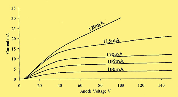
These improvements come at a price. Oxide cathodes saturate poorly, i.e. they have a pronounced Schottky effect. Fig. 3.
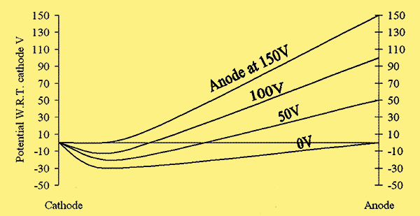
Fig. 3. Plot of the changes in potential with distance in the space between a cathode and anode [7] Handbook of Wireless Telegraphy 1938 Admiralty HM Stationery Office London 1938. With anode and cathode potentials equal, the emitted electrons form a cloud or space charge around the cathode and consequently a potential minimum. Increasing the anode potential reduces this minimum and increases cathode current until a point where the minimum is abolished ( 150 V in this example) and all emitted electrons pass to the anode and the cathode is saturated. The high voltage necessary to abolish this minimum means that electrons are subsequently substantially accelerated towards the anode which absorbs their energy and gets hot.
They also display a degree of instability of emissions which can rise or fall after a large current has been drawn because current electrolyses the coating, liberating oxygen. Further, the thickness of the coating can give it a significant resistance and produce noise. They are best suited to applications where a high output is required and where these failings can be tolerated such as in CRTs. Before the semiconductor age, oxide cathode valves were widespread in domestic equipment but their place has been taken by transistors. Today if you buy a valve amplifier you will be paying for high-end audio technology where fidelity outweighs efficiency and consequently thoriated tungsten cathodes dominate.
Oxide cathodes are fragile. Specifically they are highly susceptible to damage by bombardment by the heavy anions that result from ionisation of gas molecules in the valve. This is why practical oxide cathode valves could not be made until the technology to produce and maintain a hard vacuum had been developed. Even hard vacuums are not perfect and heavy ion bombardment remains an issue to this day. Oxide valves last routinely 1,500 - 2,000 hours compared to 5,000 - 10,000 for thoriated. The problem is greatly exaggerated if the heavy ions are accelerated to high energies before impacting the cathode. This places a constraint on the anode voltages that oxide valves can tolerate. For Vaa > 1000 volts or so cathode deterioration is excessive. This problem also affects thoriated cathodes though a process of carbonisation can limit the effect. This involves heating the cathode in a hydrocarbon atmosphere. Tungsten carbide is formed on the surface. This reduces the rate of degradation from sputtering by about 85% [2] A V Eastman, Fundamentals of Vacuum Tubes. McGraw-Hill, New York, 1941. The most resilient cathodes are of pure tungsten which is why they continued in use in high power, high anode voltage applications long after they had been superseded in other areas.
A further advantage of thoriated cathodes is that they have a small emitting surface area and so a low capacitance which is particularly important for high power high frequency applications. Where valves are operated with anode voltages of thousands of volts, powers of kW are handled with only a few amps of cathode current. The cathode heating power thus becomes rather immaterial. Such valves made to handle tens to hundreds of kilowatts for radio and TV broadcasting use thoriated cathodes. The EBAC XXX250000 is such a valve. It has a plate dissipation of 250kW, and the filament dissipates 8kW. It weighs 98 lb and measures 70 by 33cm.
Both thoriated and oxide cathodes are very sensitive to stray gas in the valve so the vacuum must be hard and this places considerable demands on the initial pumping and long term impermeability of valves. The seals between the glass envelope and the contact pins of valves have always posed a tricky manufacturing problem and these seals are never perfect, allowing the influx of small amounts of atmospheric gas over time. The surfaces of the valves components also give off dissolved gas molecules over the lifetime of the valve. To minimise the effects of gases a getter is used. This consists of a piece of a reactive metal placed inside the glass envelope and vaporised by an induction furnace or by direct electric heating during evacuation of the valve. Magnesium, titanium (thoriated cathodes) or barium (oxide cathodes) are commonly used for this purpose. The metal then precipitates on the inner surface of the valve and absorbs oxygen and other gases. This is the reason valves appear silvery (Fig. 5).
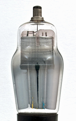
Fig. 5. Valves using oxide coated or thoriated tungsten cathodes appear silvery because of the use of a getter. This is a small amount of reactive metal that is vaporised during the valve manufacture and precipitates on the inside of the glass. Its function is to bind free gas molecules within the valve. It is called a getter because it gets free gas molecules. For a similar reason it is sometimes referred to a keeper.
Filament heater voltages deserve a brief note. Most early cathodes used between 1 and 5 Volts. In an indirectly heated cathode, the heater voltage has a slight effect on valve operation as the cathode surface potential varies from one end to the other. This tends to blunt the onset of saturation particularly at low anode voltages. This was not a particularly significant problem and does not apply to the indirectly heated oxide cathodes that had become dominant by the 1930s. Eventually by the mid 1930s 6.3V was settled on as the standard heater voltage for directly and indirectly heated cathodes. This came about because of the demand in the USA for car radios. Valves were made for this purpose with the heater voltage chosen to match the car battery voltage that was universally 6.3V at the time [5] John W. Stokes, 70 years of radio tubes and valves. ISBN 1-886606-11-0.
Recent Progress - Cold Cathodes
Electron emission is divided into thermionic, photoelectric, secondary (electrons scattered from the surface by high energy impacting electrons) and field. Field emissions are induced by a strong electric field such as that occuring at the tip of a lightning conductor during a strike. It is the field emission cathode that brings the technology up to date. Field emission cathode (FEC) technologies today fall into two broad groups: Spindt and carbon based cathodes.
In 1976 by Dr Charles A. Spindt of the Stanford Research Institute developed the first field or Spindt cathode. It consists of an array of microscopic metal points beneath a perforated metal gate. The Spindt cathode operates cold with a mode of action quite different from that of its thermionic counterpart. Electron emissions depend on electron tunnelling. In a conductor, free electrons are constrained by its surface potential barrier. The height of this barrier corresponds to the work function of the conductor. Thermionic and photoelectric emission work by giving a few electrons enough energy to pass over the potential barrier. Field emission cathodes work by modifying the barrier to maximise tunnelling of electrons which have insufficient energy to pass over the barrier, through it. To modify the barrier in this way field strengths of the order of 1016Vm-1 are induced over very short distances adjacent to the emitting surface. This is achieved with modest voltages (under 100 V) by the geometry of the emitters. Because of their small dimensions, field strengths between the points and gate are large. Field strength is greatest near conductor surfaces which curve with minimum radius as in the well known electrostatic windmill demonstration of school physics labs. Hence emissions are maximised with small sharp points. Spindt used semiconductor manufacturing techniques to produce molybdenum cones beneath holes in a molybdenum layer separated by SiO2 on a heavily doped Si wafer. He ended up with an array of conical electrodes 1.5μm high and wide at the base below 1.5μm diameter holes as illustrated in Fig. 6.
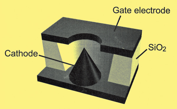
Fig. 6. A cutaway view of a single element of a Spindt cathode or FEC. Electron emissions are controlled by the gate to cathode voltage. +50 to +100 Volts on the gate turns the cathode on in this example. No heater is required.
More recent elements are of the order of 1 micron across. Spindts invention began the study of vacuum microelectronics. Spindt cathodes are made on semiconductor wafers so they have the potential to be deployed in integrated circuits. The size achievable is limited to that of wafers of about 20 cm diameter. This limits their use in display applications.
Carbon films have been under investigation because of their field emitting properties since the mid-1970s when it was discovered that hydrogenated faces of diamond crystals have a particularly low electron affinity. Diamond based films display emission via two mechanisms. As well as the above noted low affinity for electrons, high aspect ratio geometry associated with diamond crystals facilitates emission from areas with higher electron affinity. A difficulty with this technology is that diamond is not a conductor and thus injecting electrons into the conducting band is difficult. Another approach using carbon that also resulted in good field emission used graphite type carbon materials in the form of nanostructures with high aspect ratios leading to high values of electric field enhancement rather low electron affinity.
The discovery in 1991 by Japanese electron microscopist Sumio Iijima of carbon nanotubes began a worldwide research effort that has revealed extraordinary physical characteristics making them not only structures of inherent fascination but also giving them numerous potentially revolutionary applications. From the point of view of electronics, double wall nanotubes have the potential to form ultra capacitors able to store 50 Joules per centimetre cube. Extremely high thermal conductivity along the major axis raises the possibility of heat sinking. They have the potential to act as superconductors and at room temperatures metallic conductivity is achievable. This last property coupled with their extremely large aspect ratio makes them ideal for field emission applications. Current densities of over 1A/cm2 have been achieved with fields of 7 V per μm in a cathode that shows less than 10% degradation after 2,000 hours of continuous operation. This figure compares favourably with thermionic cathodes whose emissions range from around 0.1 to 3 Amps per cm square depending on the type and the temperature. Unlike Spindt cathodes, carbon based field emission cathodes are made by coating substrates such as glass or metal sheets. They thus have the potential to be made to virtually any size. This feature is highly attractive in display technology.
Field emission cathodes offer major advantages over existing thermionic technology. One of the main forces driving their development is the large potential market for flat panel display products. Successful flat displays have been demonstrated using gated FECs between 0.2 and 5 millimetres behind a phosphorescent screen, each pixel having its own set of cathodes, the colour and brightness of the pixel being controlled with cathode gate voltages. They are brighter and faster than LCD technology and have a wider viewing angle. Large scale commercial production is awaited.
Another potential use is in the manufacture of valves. Durability will have to be improved before commercial exploitation but practical valves have been demonstrated, for example a 10 GHz 27 W travelling wave tube by Makishima et al of NEC, Japan. Other diverse applications have been announced including electric thrusters for spacecraft, miniature X-ray tubes for medical robots, indicator and illuminator lights, and microwave devices. Cold cathodes look set to largely replace thermionic cathodes in the future. They also have the potential to make inroads into applications that are currently the domain of semiconductors and most significantly to extend the scope of electronics in general beyond what is now possible.
References and Further Reading.
- Fred Rosebury, Handbook of electron tube and vacuum techniques. ISBN 1563961210.
- A V Eastman, Fundamentals of Vacuum Tubes. McGraw-Hill, New York, 1941.
- History of Thermionic devices. Conference proceedings of the Newcomen Society, 23/4/1994, ISBN:0-904685-05-5.
- G F J Tyne, Saga of the Vacuum Tube. ISBN: 0-672-21470-91047.
- John W. Stokes, 70 years of radio tubes and valves. ISBN 1-886606-11-0.
- Morgan Jones, Valve Amplifiers. ISBN 0-7506-2337-3.
- Handbook of Wireless Telegraphy 1938 Admiralty HM Stationery Office London 1938.
|