|
The Miller circuit is often used in conjunction with a 'transitron', and this is probably one of the most versatile circuits in electronics. In its normal form it only requires one valve, and with very little modification may be used as a generator of sine waves, saw-teeth or square waves, as required.
Like so many circuits in wide use to-day, it originally made its appearance many years ago. It was first described by Herold in 1935. It finally came into prominence just before and during the 1939-1945 War.
Before thinking about its applications, the first thing to do is examine the circuit in its basic form.
Operation
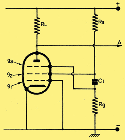
The basic circuit.
The transitron is an oscillator of a type similar to a multivibrator. That is, it does not itself produce a sinusoidal waveform. The basic circuit is shown above. It can be seen that an unusual feature of the circuit is the use of the suppressor grid in the valve.
The first relevant feature to note is that if g3 were made negative with respect to cathode, the current flowing to the anode would be reduced. G2, however, would take a greater current and the screen voltage would drop. If g3 were made more positive the anode would take more current and the screen less, therefore the screen voltage would rise. G2 and g3 are then in phase, and if coupling were placed between them, oscillation could occur. That is what, in fact, does happen.
Imagine for a moment that the suppressor was at cathode potential. The anode and screen would both be taking current. If some disturbance now occurred which caused the suppressor to become a little more negative.
This in turn would divert more current to the screen from the anode, and the screen voltage would drop further, thus driving the suppressor more negative.
This action takes place very rapidly until the suppressor is driven so far negative that all current to the anode is cut off. At this point, then. the action ceases. The charge that has accumulated on C1 during this process will now begin to leak away through Rg, and the suppressor grid will slowly become more and more positive until some current is permitted to flow to the anode. When this occurs, the screen voltage will begin to rise, because some of its current is now being diverted to the anode. The rise in screen voltage is transferred to g3 via C1, and g3 becomes yet more positive and permits more current to flow to the anode. There is, therefore, less current in the screen and its voltage rises still further, taking the suppressor with it. Once again this process continues until the valve approaches saturation, when any further increase in g3 voltage produces no increase in anode current.
At this point the action ceases, and C1 will be nearly completely discharged. C1 will now slowly charge, taking the suppressor back toward cathode potential. However, in this case, the time will be shorter than when the suppressor was cut off, because current will flow not only through Rg but also into g3. After a while, the suppressor voltage will have dropped sufficiently to regain control of the anode current.
When this occurs, the anode current will begin to decrease, the screen current to increase, the screen voltage to drop, causing the suppressor to go negative once again. Well, this is where we came in. The cycle is complete and another has started. Note that during the charging and discharging periods of C1, the screen voltage remains constant.
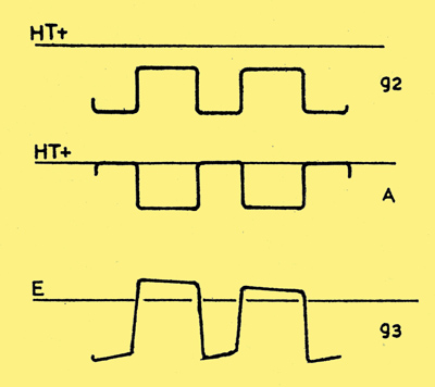
Screen & anode waveforms.
The screen waveform therefore is square in shape, as shown above. The anode waveform is also shown and can be seen to be an inverted version of the screen.
In its simplest form, then, the transitron produces a square wave of either polarity. There are very many applications where square waves are of tremendous use, but we will leave that and return to the transitron for timebase applications.
Timebases
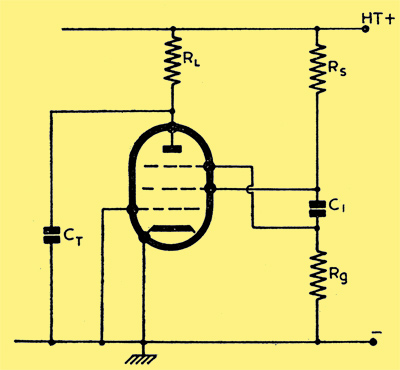
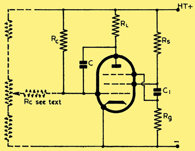
A simple timebase.
The simplest transitron timebase is shown above. The circuit is the same as before, except that the capacitor CT has been added. The transitron action is still the same as before, except that when the anode current is cut off, the capacitor CT will charge toward HT+ through the anode load resistor RL.
If the time constant of C1, Rg is just right, the circuit will begin to change state when the capacitor CT is on the way to being fully charged. The change of state will turn on anode current and the capacitor CT will discharge through the valve.
A disadvantage of this circuit is the non-linearity of the resultant sawtooth.
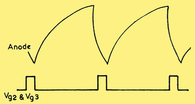
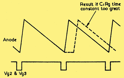
Simple timebase waveforms.
Waveforms are shown above where it can be seen that the screen waveform is essentially the same as before, but the anode waveform is a sawtooth.
An almost ideal circuit is obtained by combining the Miller circuit and the transitron. The whole circuit may be combined within the same valve, but the two parts of the circuit perform quite separate functions. The Miller connection provides the linear sawtooth, and the transitron acts as the switch which initiates and terminates the sawtooth.
Transitron and Miller together.
Waveforms.
The circuit is shown above together with the waveforms. In this circuit the two actions are comparatively separate from one another. Let us start from the moment when the suppressor is negative and there is therefore no anode current. Capacitor C, the Miller capacitor, will be charged; that is, one plate will be at HT+ , and the grid plate at cathode potential. When the transitron changes state and anode current flows, the anode voltage will drop, this drop being transferred to the control grid, via C. The Miller run-down then commences. When the run-down is complete, and the valve has 'bottomed', no fly-back will occur until C1 has charged through Rg, and the transitron has changed state.
When this occurs, the anode current will cease, and C will charge up to HT+ once more, thus completing the cycle. In order to avoid a waiting period between the end of the run-down and the fly-back, the time constant C1Rg should be chosen to cause the transitron to fly back just before the pentode bottoms. This is illustrated.
During the fly-back, a negative pulse appears at the screen and suppressor of the valve. This may be used to 'black out' the fly back trace on the CRT, by connecting the transitron screen to the grid of the CRT.
If a large range of timebase speeds are required it is normally necessary to switch the timebase capacitor C and the recycling capacitor C1. Also, if continuous variation of the timebase speed is required, RC may be returned to a point of adjustable voltage, as shown dotted. This control becomes the fine frequency control and the switched capacitors the coarse control.
A suitable point for the injection of synchronising signals is either at the screen or suppressor. If either of these points is used, care must be taken to ensure that the synchronising voltage is not too great, otherwise the trace will be distorted or may even collapse altogether.
Triggered, or single stroke operation
although infrequently used in oscilloscopes used for radio purposes, may be achieved with the circuit given. All that is necessary is to return Rg to a point sufficiently negative with respect to earth to ensure that the suppressor grid is cut off. The application of a brief pulse to the suppressor will cause the circuit to produce one sweep, whereupon it will fly back and wait until another pulse is applied.
Wide Range Oscillator
The transitron makes a very useful sinusoidal oscillator. The frequency range obtainable can be from a few cycles per second up to nearly 100 MHz. The circuit is shown in below.
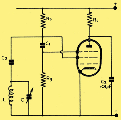
L & C are chosen for the required frequency range.
One advantage immediately becomes clear. The oscillator circuit merely requires a tuned circuit. There are no taps on the coil, and no coupling winding. For this reason the circuit is sometimes called a 'two terminal oscillator'.
The output may be taken from the junction of C2 and the tuned circuit. However, in order to reduce loading on the oscillator, a coupling winding may be introduced. If the oscillator is to be used over a wide frequency range the value of C2 would have to be switched. If the reactance of C2 becomes too high at the operating frequency, oscillation will not be maintained. Typical component values would be:
- RL = 20 kΩ
- Rs = 20 kΩ
- Rg = 50 kΩ
and C1 and C2 may be found experimentally at the frequency in use.
A Frequency Divider
The original circuit shown may be used as a frequency divider. The action is very similar to that of a multivibrator. Imagine that a synchronising signal cut off the suppressor just before the normal action of the circuit drove the suppressor into cut-off. Subsequent synchronising signals would not affect the circuit, because they would only try to drive the suppressor further into cut-off.
The cut-off condition will remain until C1 has discharged sufficiently to allow the circuit to change state. When this occurs the circuit will remain in the other condition until C2 has charged sufficiently to cause a relapse to the original condition, thus completing the cycle. The transitron will, therefore, have produced one cycle for a number of synchronising cycles, i.e. it is frequency dividing.
Valves
It is worth mentioning a few suitable valves for transitron operation. Obviously, they must be pentodes and the suppressor grid must be available at a pin. Among surplus types, the EF50 (VR91) is particularly suitable. The suppressor cut-off is in the region of 50-60 Volts. The SP61 (VR65) will work reasonably well, but the suppressor has a very long base and the valve is therefore less flexible than the EF50.
A surplus valve especially designed for the use of the suppressor is the VR116. In this case the suppressor cut-off voltage is about 10 Volts.
Among modern miniature valves are the EF91 and the 6F33. The latter is a miniature equivalent of the VR116, but an internal diode is connected between the suppressor and cathode. The EF91 makes a fairly good transitron valve, despite the suppressor grid base, which is of the order of 90 V, and very variable from specimen to specimen. Another valve is the triode pentode ECL80, which works very well in most transitron circuits, and has the extra triode free for some other purpose.
It should be remembered that the suppressor characteristic is not necessarily held within close limits on most valves (except the VR116 and 6F33) and one may therefore strike an occasional valve which will not work in a transitron circuit, but which is perfectly good in every other way.
|