The EF91 was almost the universal valve of the early 1950s, as can be seen by the number of manufacturers who made versions of this standard valve. The first reference we have to the EF91 is the review of the 1947 Olympia Show in Wireless World.This envelope has a more rounded shape than EF91.The EF91 is a high gain, high impedance, high slope, screened pentode. Mullard describe the EF91 as primarily intended for use as RF amplifiers or mixer valves in television receivers. At the time, late 1940s, television only operated at VHF.If run hard as in video amplifier service or as a TV sound output valve, the EF91 would give problems but for RF or IF use it was a reliable valve.It could be used from AF to VHF up to about 200 MHz and was found in large numbers in most types of electronic equipment. In radio it was used for RF and IF amplification, for oscillators and frequency multipliers.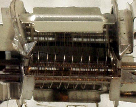
The electrodes fill the width of the valve. The anode is formed by two rectangular plates at either side of the valve. The other two sides of the box being completely open. All three grids can be clearly seen and all three grids have separate pins, unlike so many valves that strap the suppressor grid to cathode internally. The cathode is a flattened tube, g1 is closely wound and very near the cathode. The screen grid, again of thin wire, is a flat sided helix. The final grid is placed halfway between cathode and anode and is of a much looser pitch than the other grids.The thin glass tube envelope is 17 mm in diameter and, excluding the B7G base pins, is 46 mm tall.References: Data-sheet & 1040 Type EF91 was first introduced in 1947. See also 1947 adverts. |


