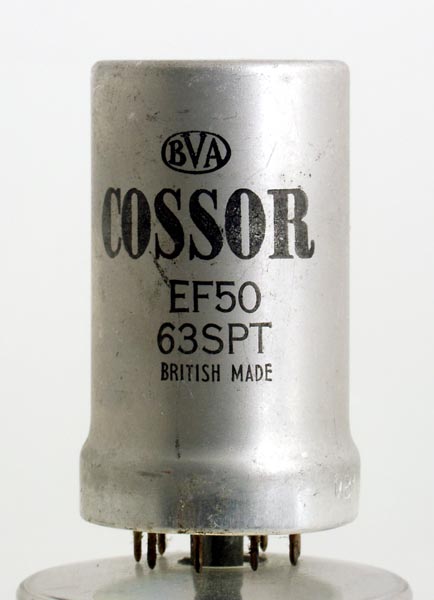
The EF50 was one of the 'wonder' valves of WWII making possible high frequency IF strips (45 MHz) for Radar. It was also a relatively short lived valve and was thus manufactured in vast quantities. Known as a red valve, this clone made by Cossor shows that plain canned vessions also were made.This amplifier pentode was a general workhorse. It was extensively used in radio and radar during WWII.Mullard, the UK arm of the Dutch multinational Philips, describe the EF50 as being fully controlled by a grid voltage of 0 to -6 or 0 to -55 Volts, according to the circuit configuration.The pins are equi-spaced around the circumference of the B9G pin circle.The dimensions are 32 mm in diameter for the body of the screening can, and 60 mm in length, excluding the short pins and the central spigot that locates the pins and covers the evacuation seal, as well as providing a connection for the screening can.References: Data-sheet & 1040. Type EF50 was first introduced in 1939. See also 1939 adverts. |