|
Practical uses of the transitron.
A test oscillator is an instrument that every seriously minded radio man, amateur or professional, should have. While the oscillator to be described in this article is not intended to replace a well-designed signal generator, it has many uses, and only costs a fraction of the price. It cannot be used for absolute sensitivity measurements, although it will give the owner a fair idea of the performance of any receiver.
The Transitron oscillator can be used with advantage as a test oscillator, making use of the grid amplitude control as an attenuator. Several experiments have been carried out since the transitron oscillators article was written, and in the first circuit that was tried rather a novel form of modulation was incorporated. The idea was not original as it had been suggested by Brunetti in his paper on the Transitron in 1934. He did not mention, however, that over-modulation is unavoidable. For a simple oscillator this is not so important, and the circuit, for what it is worth, is shown in Fig. 1.
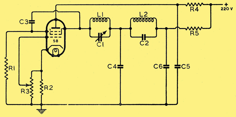
Fig; 1. Original Transitron oscillator circuit. Values of components R1 100 kΩ, R2 2 kΩ, R3 0.5 MΩ, R4 7,5 kΩ, R5 25 kΩ, C1 0.0005 μF, C2 0.03 μF, C3 0.01 μF, C4 10 μF, C5, 1 μF, C6 1 μF.
It will be noticed that both the RF and AF oscillatory circuits are in series, one modulating the other. If R, the inherent dynamic resistance in both circuits, is made equal to the negative resistance of the valve, oscillation takes place in both circuits, and hence the lower frequency modulates the higher. In both coils the 'Q' must be fairly high; this is.more important in the case of the L2 circuit, in which the production of oscillations is more difficult than in the other, also, the screen and anode voltages are fairly critical. Oscillation in the L1 circuit will take place over wide limits, but often L2 will not oscillate until L1 is first short-circuited. This can, however, be overcome by altering the anode potential. A number of different coils were placed in both circuits, and, with the resistances and voltages shown, both circuits 'kicked off' every time.
It should be noted that no iron is shown in the L2 circuit, although the frequency is in the order of 800 Hz. An iron-cored choke, of course, may be used, but, due to hysteresis, a pure sine wave is not possible. The resistance R3 is used to bias off the oscillator and may be used in place of an attenuator, as explained in the previous article. A Type 58 valve is recommended, as this valve has a linear negative characteristic, and hence excellent control of amplitude is obtained. Of the English valves the Osram VMP4 and its equivalents are suggested, although these have not so far been tried.
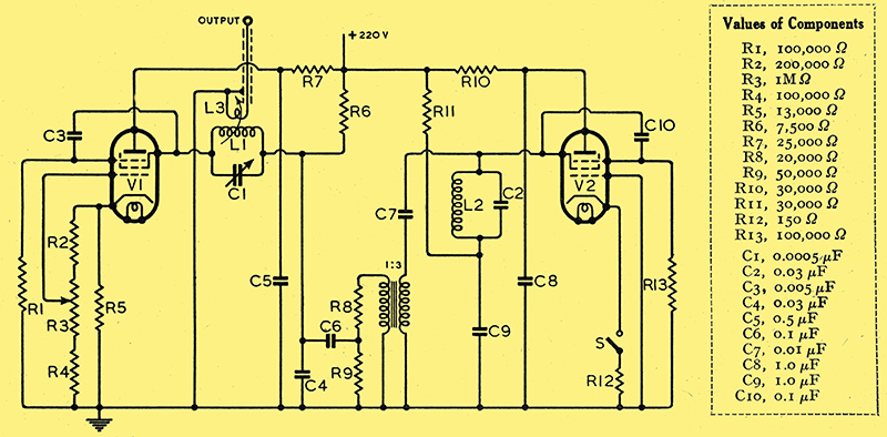
Fig. 2. Modified Transitron oscillator circuit. All resistances may be half-watt, except R3, which should be 2 Watt.
The circuit of Fig. 2 is slightly more elaborate, but overcomes the difficulty of over-modulation experienced with the arrangement of Fig. 1. The valve V1, with its associated circuit, L1, C1, acts as the RF oscillator. R5 is the automatic bias resistance, supplying approximately 45 Volts bias. R3 is a 1 MΩ potentiometer placed in parallel to control the amplitude of oscillation; R2 and R4 are placed in series to give better control, It will be noticed that the usual bypass capacitor across R5 has been omitted, for the following reason. RF voltage is developed across the bias resistance R5. When the grid is connected to the cathode end of R3, since it is in phase with the cathode, a certain amount of feedback takes place, and the amplitude of oscillation is increased. As the grid is taken nearer to earth, less and less feedback is possible, and, at the same time, bias is being applied which is reducing amplitude. With this method an extremely fine control is possible. With a by-pass capacitor in circuit only a 2:1 ratio of amplitude control is possible.
AF Modulation
The valve V2 is the modulator; in this case a Mullard EF50 was used as another 58 could not be procured. The same Transitron circuit was used, giving a pure output at about 1 kHz. This is transformed down through a 1:3 transformer to the RF circuit (a 3:1 audio transformer reversed was used for this purpose). The reason the step-down transformer and associated network R8, R9, was incorporated was to stop over-modulation, as the output from the EF50 was too great. By using another 58 valve in place of the EF50, and taking its grid through a decoupling network to the centre point of R3, constant modulation could be obtained, and the writer hopes to do this as soon as another 58 can be obtained.
With the present network, approximately 30% modulation is obtained at maximum output, the 100% mark being reached when maximum bias is applied to V1. This is not a good point, as it is a little misleading when using the oscillator to line up a receiver. It is recommended that those building this instrument should include precautions against over-modulation as described.
Coil data has not been included in this article, as any coil can be pressed into service or wound to the desired frequency with the aid of a Wireless World ABAC. The writer had some old honeycomb coils, which were used for the medium and long waves. IF coils obtained from the junk box were used for the intermediate frequencies, and short-wave coils were also retrieved from the same place.
The approximate output at a 1 MHz is just over a Volt, which is ample for most purposes and corresponds to the output of a commercial generator at this frequency. It is necessary to find the optimum coupling for L3 for each band. For this coupling coil about six turns was found to be correct for the medium and long,waves. Naturally, as the frequency increases the coupling is decreased to keep the ratio correct.
It is preferable to house the oscillator in a screening box, although, due to the attenuator system, this is not essential, as the total radiation is cut down when the bias is increased. With the usual type of test oscillator the attenuator, of course, is in the output only, and unless the instrument is carefully screened, direct radiation takes place and the attenuator is rendered useless.
Characteristics of the Type 58 Valve.
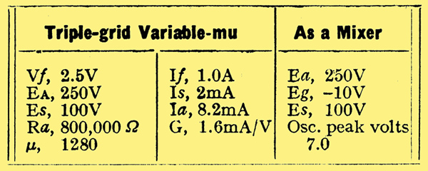
The figures for the Type 58 valve, which, as a matter of interest, are given in the table, were obtained from the American ARRL Handbook. The 2.5 Volt filament presents a little difficulty, but, as the voltage is so low, it is a simple matter to wind on about ten or so turns on to any transformer over the top of the outside winding to obtain this voltage. Most transformers have space enough for about one layer of 20-gauge enamelled wire.
Calibration of frequency is best carried out with the aid of a good all-wave receiver, whose frequencies are known to be correct. Failing this, with the modulation switched off (switch S) the oscillator can be made to beat with a few known stations; interpolation will do the rest.
Calibration of the audio-frequency side can best be-checked against a piano, middle G sharp being approximately 400 Hz; for more accurate work a tuning fork could be used, though it is unlikely that any high degree of precision will be required on the audio-frequency side of an oscillator of this type.
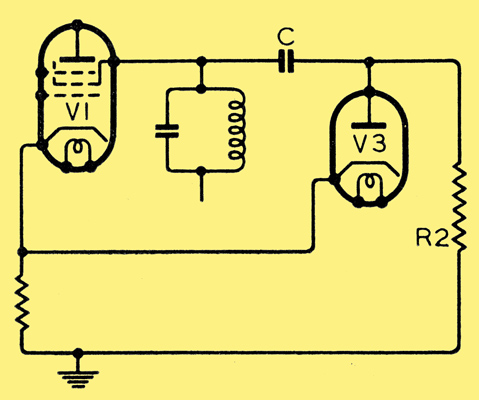
Fig. 3. Circuit for automatic amplitude control. R2 0.5 MΩ, C 0.1 μF.
Automatic amplitude control may be added, as a refinement, and, for those who are interested, this is shown as a separate circuit (Fig. 3). The output from V1, the oscillator, is taken through C to a diode V3, which can be any triode with its grid strapped to anode. This small voltage is rectified and taken back to the auto-bias circuit. Hence any small variations in amplitude alters the bias by an equally small amount, thus keeping the signal constant.
|