|
Wide range and high frequency stability with untapped coils.
Most readers of this journal are familiar with Hull's famous Dynatron oscillator. A similar circuit, not so well known, is the negative transconductance oscillator discovered by Herold [1] Negative Resistance. E W Herold, Proc IRE, Oct. 1935. in 1935, and later developed and renamed the 'Transitron', by Brunetti [2] The Transitron Oscillator by C Brunetti, Proc I RE, Feb. 1939.. in I939.
This oscillator possesses essentially the same type of, negative-resistance characteristic as the Dynatron, having all its advantages without its disadvantages. Its characteristic is independent of secondary emission, and remains practically constant for the life of the valve. Like the Dynatron, it is a low-powered oscillator, and will oscillate from 600 Hz to 60 MHz by changing the value of the associated LC circuit. See here for a practical example.
Brunetti reports that when properly designed, changes in frequency resulting from a 33%. change in screen volts may be kept within 10 parts in 106, and that its stability may be compared with that of a crystal oscillator. Another great advantage is that no centre tap is required as in other types of oscillators. All that is necessary to switch from the 160 metre amateur band to 5 metres is to change the coil!
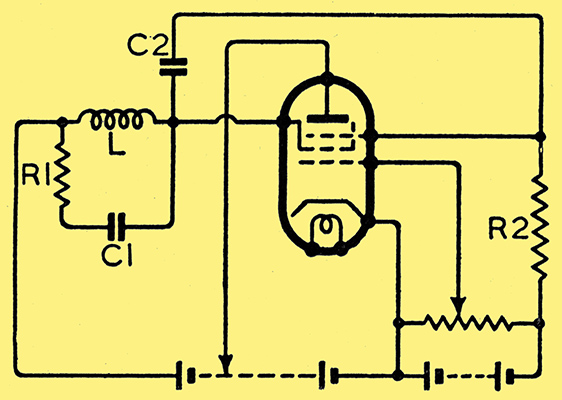
Fig. 1. Basic circuit of the transitron oscillator.
The writer first built up a battery model on a bread board. The circuit which is extremely simple, is shown in Fig. 1, the action being as follows: Negative voltage applied to the suppressor causes electrons that have passed through the screen to be returned. Over a certain range, a positive increment of suppressor voltage allows more electrons to go to the anode, and thus decreases the screen current, which means that the suppressor-screen transconductance is negative. When this negative resistance becomes equal to the equivalent resistance of the tuned circuit (R1 in Fig. 1), oscillation results. Fig. 2 shows the screen current/screen voltage characteristic, O being the operating point.
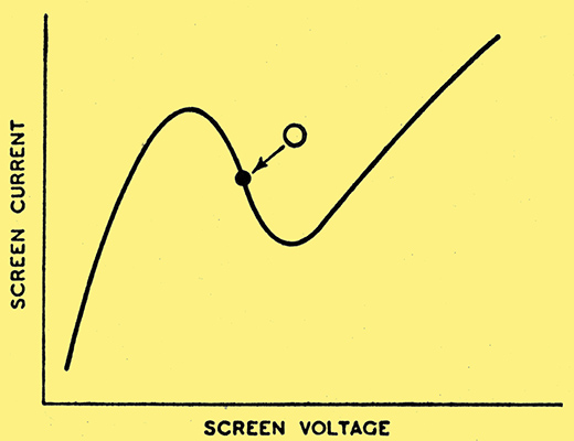
Fig. 2. Screen-current/screen voltage characteristic of the transitron. The operating point is at O.
The relative values of C2 and R2 are important; if they are so small that the reactance of C2, is appreciable in comparison with R2 at the desired frequency of oscillation, then the voltage-dividing action of C2 and R2 causes the change of suppressor volts to be less than that of the screen, and the system stops oscillating.
As with the Dynatron, it is desirable to keep the amplitude of oscillation small so as to keep the waveform and frequency stability good. If a small negative bias is applied to the control grid, the total current flowing to the screen may be controlled and the negative slope of the current/voltage characteristic may be varied. Hence a flexible means is available for varying the magnitude of the negative resistance, and thus the amplitude of oscillation. By arranging for the oscillation voltage to regulate the bias on the control grid, additional amplitude control may be obtained.
The 3 MHz coil was then put back to make certain that it was still correct at this frequency, also the output was connected to an oscilloscope to observe the wave form. It was seen to be a pure sine wave.
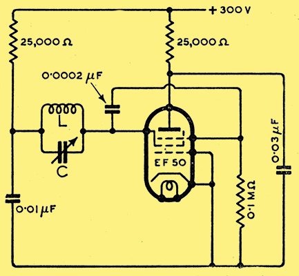
Fig. 3. Practical circuit for frequencies up to nearly 100 MHz.
Fig. 3 shows the circuit used. It will be noted that suppressor bias has been omitted, as it was found unnecessary with this type of valve. For those who are interested in this particular circuit, the following operating. conditions are included. In an oscillating condition, at approximately 3 MHz, with the values shown, anode current is 4.5 mA and screen current 7.6 mA; in a non-oscillating condition anode current is 10 mA, and that of the screen 3 mA.
Although it did not occur to the writer at the time, it is felt that if the metal screen covering the valve had been removed, it might have been possible to go higher still.
Other suitable pentodes Brunetti suggests are the American 57, 58, 59, 6C6, 6J7 and 6K7. The Osram ZA2 acorn pentode was tried, but could not be made to oscillate.
The enormous scope for this oscillator will be seen from the fol-lowing list of advantages:-
- Stability.
- Simplicity.
- Ease with which output can be controlled.
- Purity of waveform.
- Ease in band changing (i.e., only one inductance required).
- Almost any pentode valve will suffice.
The only disadvantage seems to be that only low outputs can be expected if (a) and (d) are to be satisfied.
Putting the above advantages to practice, the writer has the following applications in, mind:-
General Purpose RF and AF Oscillator
An oscillator that will cover from 600 Hz to 60 MHz with a variable amplitude control, in place of the usual attenuator, is an attractive proposition for the amateur. Previously a Dynatron has been used with a specially selected valve which is dependent upon secondary emission, a property which is extremely variable with age, and which varies widely in valves of the same type.
Local Oscillator
The local oscillator in a superhet receiver, with its inherent drift and large number of coil connections for band switching, has always been a source of trouble to the designer. It is felt that this oscillator could be utilised with advantage on account of its excellent stability and simplicity.
Frequency Meter
In the past, the electron-coupled oscillator, with its inevitable cathode tap, has been used for this purpose. Here, now, is an oscillator which is more stable and only requires a coil with two connections.
Crystal Oscillator
The output from a Transitron must be kept low if used in place of a crystal oscillator, in which case it would have to be followed by a stage of RF amplification, but, incidentally, this also applies to the electron-coupled oscillator, so widely used by amateurs in the past. The variable output control could be utilised with advantage as a control for varying the amount of drive required for the following stage. Again there is the advantage of two-pin coils for easy band changing. It is suggested that link coupling be used to avoid any undue loading which might spoil the stability of the oscillator.
References
- Negative Resistance by E W Herold, Proc IRE, Oct. 1935.
- The Transitron Oscillator by C Brunetti, Proc I RE, Feb. 1939.
Further Comments
Use of a heptode.
Design Limitations.
|