|
EF50's Galore
The overall size of the chassis of the Pye B18T television receiver, in which the makers have dispensed with a mains transformer, is little bigger than a standard broadcast set. By using an inclined chassis the nine inch CRT has been accommodated in a minimum of space.
The paragraph above is the write-up given in the Wireless World at the time. The very first television chassis I took apart as a teenager looked exactly like the picture above. The image is the cover photo of the magazine.
The EF50 was designed in 1938 by Philips of Eindhoven for Band I television receiver use and first released in 1939. It was extensively used in radio and radar during WW2 and television was blacked-out for the duration.
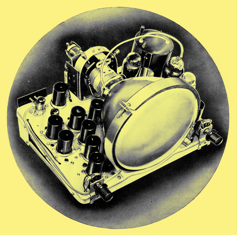
This chassis shows the wide range of stages that the EF50 was suitable for. The short pins made the valve difficulty to retain in the B9G holder if subjected to vibration.
The input stage uses a miniature valve that was probably an EF91. The EF91 was released in 1947 and had superior RF performance to the EF50 but although used in very many designs of all sorts of equipment for decades to come, it was superseded for TV by the EF80 in 1950.
On the right of the picture tube is the octal based HT rectifier. There is no HT transformer so this is a half wave type. The line output valve top cap goes to the black cylinder that is the line output transformer and EHT generator. This type of 9 inch set would have used less than 10 kV on the final anode of the tube. The days of bonded faceplates with built-in safety glass were far into the future in 1948 and the tube is held in place by a steel band and foam packing. The cabinet would have a safety glass sheet fixed to the wooden front panel.
Pye B18T: 9 inch Television Receiver
Wireless World, September, 1948
First UK AC/DC TV
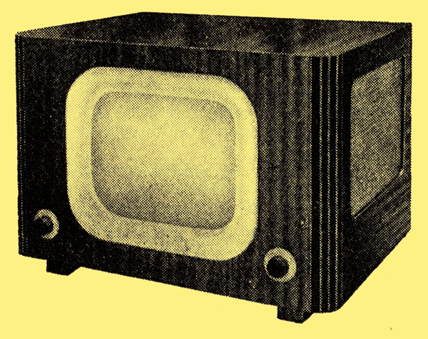
In the B18T table model, the loudspeaker grille is at the side of the cabinet.
Designed on the familiar lines of the AC/DC broadcast receiver, with series-connected valve heaters and a half-wave rectifier for the HT supply, the Pye B18T television receiver has no mains transformer. The set is the first on the market in which this technique has been applied to television.
The makers state that the set is designed for use on AC mains of 230-250V, 50 Hz, and that for supplies of 190-220 V an auto-transformer is necessary. They make no mention of the possibility of operating the set from DC mains. However, there is no obvious reason why this should not be practicable and, in fact, a model has been seen operating satisfactorily from a 240 V DC supply. Presumably, however, DC operation would be limited to supplies of not less than 230 V.
The advantages of doing away with a mains transformer are chiefly the reduced weight and size of the equipment. The dimensions of the set have been brought down to 17.25 in wide by 12.25 in high by 12.75 in deep and the weight to only 30 lb. This is a considerable achievement for a set with a 9-in tube (picture 7.5 in by 6 in).
The major difficulties in design with an HT supply of the order of 200 V only obviously lie in the line-scan circuits. The circuit is a more-or-less conventional blocking oscillator feeding a pentode valve which in turn feeds the deflector coils through a transformer. A damping diode is connected across the secondary and results in a considerable increase of efficiency. The primary is arranged as a step-up auto-transformer to increase the magnitude of the high-voltage pulse on fly-back. This is fed through a half-wave valve rectifier for EHT, the filament of the rectifier being fed from a winding on the line-scan transformer. As the current in this transformer must be kept constant if the filament of this valve is to be kept operating under proper conditions, the usual picture-width control by valve input is impracticable. A variable inductance in series with the deflector coil is used instead.
A permanent magnet is used for focusing. It has an adjustable shunt, but as there is no temperature drift, focus is no longer a panel control It also needs no current. The frame scan is produced by a blocking oscillator feeding a pentode which is transformer coupled to the deflector coils. Sync separation is effected by a pentode and two diodes.
The receiver portion comprises a straight vision channel with four RF stages, diode detector and one VF stage. A second diode across the VF input acts as a noise limiter. The sound signal is picked out of the cathode of the third RF stage and after amplification in two further stages is fed to a diode detector and thence through a diode noise limiter to the pentode output valve. AGC is provided on the sound channel, delay being obtained with the aid of a metal rectifier.
The HT circuit comprises a half-wave rectifier with a 50 μF reservoir capacitor and smoothing is effected by a single choke followed by a 100 μF capacitor. The valve heaters are series connected, including the CRT heater; a tapped resistor is included for adjustments between 230 and 250V and there is also a thermistor in circuit as a regulator.
The set has 19 valves and the tube and costs 38 gns, plus purchase tax. The panel controls are sound volume, on-off and picture brightness only. The usual pre-set controls for line and frame hold, contrast and noise limiter among others are accessible at the rear of the cabinet.
|