|
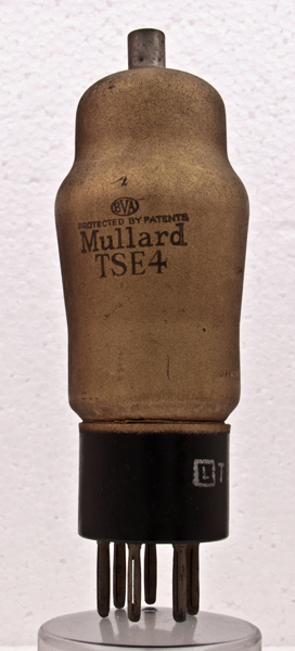
The TSE4 represents the first practical television RF valve based on secondary emission. The article on secondary emission from Wireless World cited above explains why this was an area of development in the race to achieve good gain at high frequencies. Here high refers to 45 - 50 MHz where sufficient bandwidth for television high definition video could be achieved. It was also a requirement for RADAR development.The TSE4 is in the same envelope and base format as the TSP4 RF pentode. The TSE4 was eclipsed within months by the EE50 secondary emission valve. The EE50 used all glass construction to reduce capacitances over the TSE4's pinch construction. Secondary emission was a research avenue because no practical solution to the problem of very small cathode to g1 spacing and thus grid overheating and grid electron emission had been found by 1938.Secondary emission valves were noisy and later versions were in fact used as noise sources in jamming equipment.The development of RF amplification and high mutual conductance by secondary emission means was ended by the appearance of the EF50 - a practical valve with high gm through small k-g1 spacing.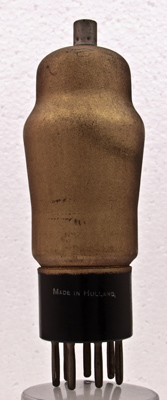
The base shows that the TSE4 was developed by Philips in Holland as were the EE50 and the EF50.The classic envelope is 46 mm in diameter, and excluding the B7 base pins is 119 mm tall.References: Data-sheet & Internet & books various. Type TSE4 was first introduced in 1938. See also 1938 adverts. |
Pin Connections
| 1 | 2 | 3 | 4 | 5 | 6 | 7 | tc |  m | a | k2 | h | h | k1 | g2 | g1 |
|
|
Absolute Maximum Operating Conditions
| Vh | Ah | Va | Vs | Vg | mAa | mAs | ra | gm | 
| 4.0 | 1.1 | 250 | 250 | -7 | 8.0 | 0.7 | 0.1M | 14.5 |
|
Updated December14, 2012.
|
|