|
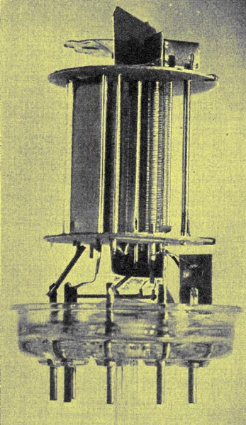
The location of components within the EE50
Secondary emission valves usually have a single stage of electron multiplication and the EE50 demonstrates their operation. This valve is rated to operate with a HT of 300 volts, and has a slope of 14 mA/V. It was primarily designed for use in television receivers, where, due to the bandwidth required, the stage gain is low with conventional valves from the late 1930s.
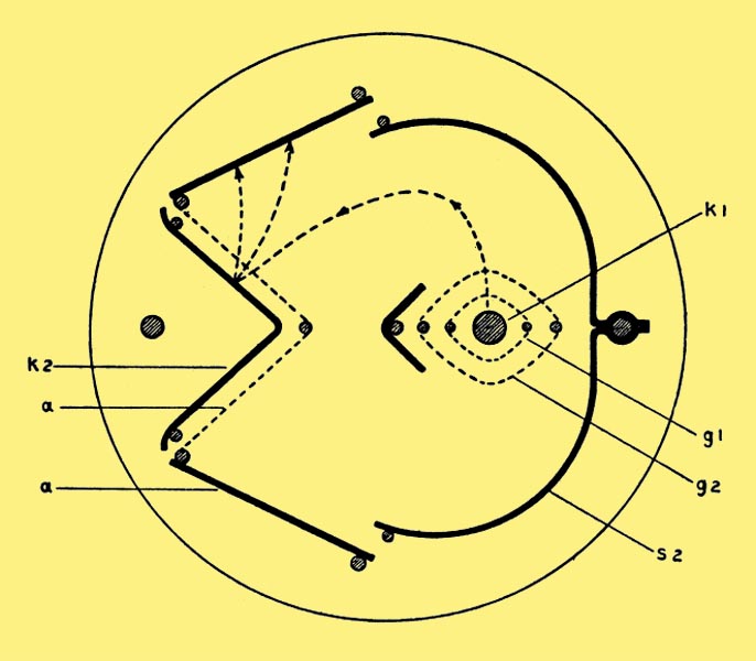
Above is a cross section of a Mullard EE50 single stage electron multiplier showing the path of the electron stream by dotted line. k1 is the main cathode (which is indirectly heated) and g1 is the control grid. g2 is the screen grid, which is intended to screen the control grid from the remainder of the valve in order to raise the effective voltage in the region of the control grid and to increase the internal impedance. The screening electrode S2, which is maintained at cathode potential, deflects the electrons accelerated through g2 towards the secondary or second cathode, k2. The other small shield in the centre of the valve prevents a direct electron flow between k1 and k2, and also prevents any cathode material from being deposited upon k2 during processing. The electrons deflected by S2 impinge upon k2, where the secondary electrons are liberated and attracted towards the anode a. The part of the anode opposite, and in close proximity to, the second cathode is made of gauze mesh in order to allow the passage of both primary and secondary electrons.
In operation the control grid obtains its bias by means of a resistance in the cathode lead, whilst the screen grid g2 is maintained at HT line potential. The screen current is usually about 0.5 mA, and the anode current about 10 mA. The second cathode, k2, is maintained at a voltage of about 150 volts by means of a potentiometer network, but, as is usual with secondary emitting electrodes, the current is negative and has a value of about 8 mA.
|