|
A distinct departure from normal valve practice is described in this article and it is one which is of especial interest to the television worker. By making use of secondary emission a considerable increase in mutual conductance is obtained without a corresponding increase in the inter electrode capacities.
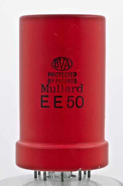
The Mullard EE50.
For some types of apparatus, especially for television amplifiers, valves having very high mutual conductances are necessary to obtain useful amplification with circuits of only low impedance. It is also important that this high value of mutual conductance be unaccompanied by any great increase in valve capacities or input damping.
There are several methods by which a high mutual conductance can be achieved in a radio valve. For example, the cathode area can be increased to give a higher emission, which necessitates a higher cathode-heating wattage to maintain the same operating temperature; or the distance between the cathode and control grid can be reduced. Both these solutions have the obvious and important disadvantages of increased heat development, a tendency to primary grid emission and increased inter-electrode capacities. For operation at very high frequencies both temperature effects and high capacities are to be avoided.
Other methods of increasing the mutual conductance have been explored and the application of secondary emission has been found to be a satisfactory solution. Making use of this principle a valve has been developed which attains the high mutual conductance of 14 mA/V. with low input and output capacities and acceptable input damping.
The original development of the secondary emission valve was made available in the TSE4, which is now superseded by the type EE50 in the new 'all-glass' construction, providing additional electrical and mechanical advantages.
Electrons emanating from a cathode traverse the intervening grid or grids and impinge upon an electrode where secondary electrons are liberated as a result of the bombardment. These secondary electrons can move away from this electrode under the influence of a relatively positive potential at which an adjacent electrode is maintained. The electrode at which the secondary emission occurs is known as the secondary emission cathode or auxiliary cathode and its efficiency as a cathode is expressed by the secondary emission factor §. This factor is the average number of secondary electrons released for each of the electrons striking the auxiliary cathode, and usually known as the primary electrons.
The Auxiliary Cathode
The quantity and path of the secondary electrons depend upon the mechanical arrangement and the potentials of the electrodes, as well as the physical properties of the material at the surface of the bombarded electrode. The materials normally used in the construction of valves have low secondary emission factors. For instance, in a valve having a nickel electrode at 150 Volts positive with respect to the cathode, § = 0.94, and it is not possible to obtain electron multiplication using nickel under these conditions because the total secondary emission from the electrode will be less than the primary current flowing to it.
The behaviour of secondary electrons in a valve depends mainly on the potential gradient in the vicinity of the electrode from which they are liberated, that is on the type of valve and its operating conditions. As an example, take the case of a triode which normally operates with the anode at a positive potential and the grid biased negatively; any secondary electrons which leave the anode soon lose their initial velocity and return again to the anode because there is no other positive electrode to attract them. The conditions in a tetrode, however, are usually different and secondary emission from the anode is drawn towards the positive auxiliary grid unless the valve has been specially designed to avoid this effect by critically spacing the electrodes. By making use of a material having a secondary emission factor greater than unity, electron multiplication can be achieved and the method adopted is illustrated below.
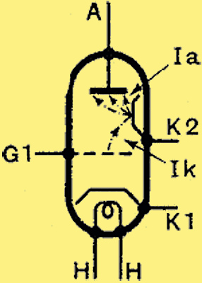
In this diagrammatic representation of the new valve the path of the electrons is shown by dotted lines.
The primary electrons pass from the cathode k1 through the control grid g1 in the usual manner and are then subjected to the influence of certain other electrodes, omitted from the diagram above for simplicity. These direct the electron stream towards the auxiliary cathode k2 which is suitably treated to have a high secondary emission factor.
The Secondary Current
The secondary electrons liberated are then attracted towards the anode and form the anode current. This current is greater than the primary current by an amount dependent upon §. The grid controlling the primary current will, therefore, influence a greater anode current and a higher mutual conductance than normal is obtainable. As each primary electron liberates several secondary electrons which pass to the anode, the supply of electrons at the auxiliary cathode must be supplemented from an external source. While in normal multiple grid valves a negative charge is led away from the positive electrode, it is necessary to supply a negative charge in the case of the auxiliary cathode of secondary emission valves. In the application of secondary emission for electron multiplication many problems arise. The presence of the cathode and secondary emitting electrode in the same bulb can result in the secondary emission surface becoming coated with a layer volatilised from the cathode (Ba, BaO). The effect of this is to reduce the secondary emission factor, but assuming that this and other difficulties can be surmounted by suitable design, it is of primary importance to investigate the possibilities of the application of secondary emission.
Comparing two valves designed for a similar purpose, one employing secondary emission and the other of usual design, it will be found that at the same anode current the mutual conductance of the secondary emission valve is appreciably higher than that of a valve not using secondary emission. Two of the factors which limit the maximum mutual conductance and anode current are the maximum permissible anode dissipation and the maximum secondary emission obtainable from the auxiliary cathode.
The Electrode System
It can be shown that for the same values of anode current and for valves of similar design, a secondary emission valve has a mutual conductance greater than a normal valve by the factor §1/K. Moreover, its mutual conductance is proportional to §1/K under these conditions.
Except at low cathode currents the constant K has a value of about 1.6 and the mutual conductance is therefore proportional to §0.6. In a valve having an auxiliary cathode for which § = 5, the mutual conductance will be 506 = 2.5 times that of a valve without secondary emission for the same anode current.
The difficulty due to volatilisation of the cathode coating has been overcome in the Mullard secondary emission valve by deflecting the electron stream. As volatilisation in vacuo takes place along practically straight lines, the remedy lies in the use of a construction in which the auxiliary cathode is screened from the volatilised material emanating from the cathode. The electrons emitted from the cathode can be deflected on to the auxiliary cathode by an electrostatic field.
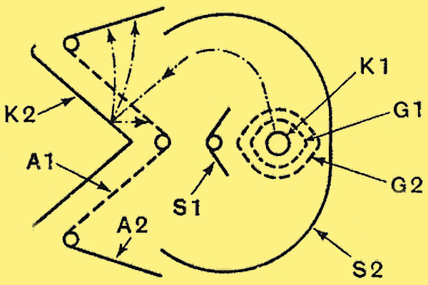
The general arrangement of the electrodes is shown here together with the electron paths.
The diagram above shows the basic arrangement of the EE50. The cathode k1, the control grid g1 and the auxiliary grid g2, which operates at 250 Volts positive with respect to the cathode, are similar to an ordinary tetrode valve. The auxiliary cathode k2, operating at 150 Volts positive with respect to the cathode, is protected from the cathode material by the screen-s1, which together with screen s2 is at cathode potential.
The effect of these two screens at low potential, in conjunction with the anode a1 and auxiliary cathode at a high positive potential, is to direct the primary electron stream along the path indicated by the dotted line in the diagram, towards the auxiliary cathode k2. The divergent stream of electrons emerging from the screen grid g2 is refracted and finally, as two convergent beams, impinges on the auxiliary cathode, where secondary electrons are dislodged and accelerated through the open mesh of the anode, situated at about 1.5 mm. from the surface of the auxiliary cathode, to be collected by an anode a2 made of solid material. Although this anode is a continuation of a1 it is not made in the same form, because there would then be a tendency for electrons to oscillate in the spaces between the wires, giving rise to increased output damping when operating at the higher frequencies.
The Anode Voltage
If the open-mesh anode is not present, the potential difference between the remaining anodes and the screen grid would need to be considerable in order to establish a potential gradient at the surface of the auxiliary cathode high enough to draw all the secondary electrons to the anode. In any case it is obvious that the anode must be at a higher positive potential than the auxiliary cathode, and in the EE50 the anode voltage has been fixed at 250 Volts, and it is then 100 Volts positive with respect to the auxiliary cathode.
Grid Bias
The advantages of the EE50 are of special value in wide-band amplifiers using low-circuit impedances, such as television amplifiers. Due to the high mutual conductance of 14 mA/V, the high AC resistance (>100,000 Ω) and low input and output capacities, it is possible to obtain appreciable amplification with the low circuit impedances necessary to obtain a uniform response over a wide band of frequencies. When using this high value of mutual conductance it is, of course, necessary to take adequate precautions against instability.
A practical point of some importance is the method of providing bias for the control grid. Valves are usually biased by means of a cathode resistance, and the working point on the characteristic is given by the intersection of the resistance line OA with the curve, as illustrated below.
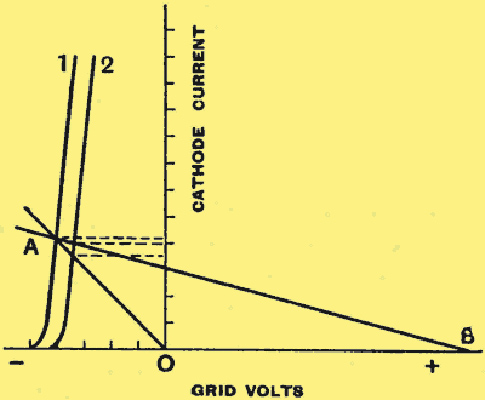
This diagram illustrates the effect of the bias system adopted.
Small differences in the characteristics of valves or small variations in the operating voltages then cause only slight changes in the anode current. In the case of the EE50 the negative bias for the control grid is also obtained from a resistance in series with the cathode. But since the bias is a function of the cathode current and this does not include the anode current, which is supplied by the auxiliary cathode, the compensating action of the bias is negligible. Special measures have, therefore, to be taken to provide some compensation. This can be effected by using a higher value of cathode resistance as indicated by the line BA in the diagram above and applying a positive counter voltage to the grid so that the initial working point is the same as before. This positive voltage is represented by OB.
The line BA shows the total bias developed across the cathode resistance as a function of the cathode current; and comparing it with the line OA it will be seen that the variation of cathode current between the conditions of curves 1 and 2 is considerably reduced by the adoption of the higher value of cathode resistance.
Under the conditions usually encountered in the circuit of television amplifiers, where parallel damping resistances of less than 5,000 Ω are used to obtain satisfactory response over wide frequency bands, it can be shown that the stage gain is proportional to gm/C, where gm is the mutual conductance of the valve and C the total capacity in parallel with the anode circuit.
This capacity is the sum of the output capacity of the amplifier valve, the input capacity of the succeeding valve, stray capacity of the circuit and the self-capacity of the coil. The input capacity referred to will include the additional grid capacity due to Miller effect in the valve which is equal to Cga multiplied by the amplification in the valve.
Comparing three types of valve previously available, i.e., an RF pentode, VP4B, a television pentode TSP4, and an acorn pentode AP4, the following results are obtained when the stray capacity of the circuit is assumed to be 6 pF.
Valve | Mutual
Conductance gm mA/V | Total
Capacity C pF | Ratio gm/C |
VP4B | 2.0 | 19.5 | 0.11 |
AP4 | 1.4 | 12.0 | 0.11 |
TSP4 | 4.7 | 24.0 | 0.20 |
It will be clear that improvement in the ratio gm/C can be obtained by increasing the mutual conductance or reducing the total capacity C, which involves a reduction in (Cak+Cgk).
Thus, the acorn valve AP4 gives a slight increase in gm/C compared with the VP4B, in spite of its lower mutual conductance. Moreover, it has been assumed that the stray circuit capacity would be the same for both these valves, which is unlikely in practice, and the acorn valve would probably show a greater improvement than that indicated.
Owing to the very high mutual conductance the secondary emission valve represents a considerable improvement. The ratio gm/C amounts to 0.68 for the EE50, assuming the same stray capacity of 6 pF. and the stage gain is nearly four times that of the TSP4. Another application of the EE50 in addition to RF and IF amplifiers is its use as a phase-splitting valve in push-pull amplifiers. In this application, use is made of the fact that the auxiliary cathode current flows in the opposite direction to that of the anode current. If suitable load resistances are connected in series with the anode and the auxiliary cathode, the alternating voltages developed across these resistances will be in phase opposition and can be used for driving a push-pull stage.
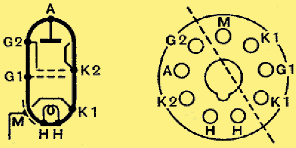
Arrangement of electrodes and base connections. The dotted line across the valve holder indicates the correct positioning of the inter-stage screen located below the chassis.
Operating data for the EE50 and other valves discussed can be found in their museum entries by following the links.
|