|
Many references give the impression that the UK Armed Services CV List valve CV138 is the later military version of the flock of equivalent 6F12, EF91, 6AM6, Z77 etc. high slope B7G base pentodes from many British manufacturers, which were widely applied in television & other equipment from the later 1940s.
However, the December 1944 CV valve list has the CV138 in the part of the list for newly introduced types, with the prototype listed as X138, description - RF pentode B7G - and specification sponsor as MAP (Ministry of Aircraft Production) - not any commercial type.
In the 1946 CV List, CV138 is listed with characteristics and pin-out matching the later CV138 specification. The prototype is given jointly as V888 & DDR1F.
In the history of Mazda valves, the Brimsdown factory produced B7G valves 'during the second World War', (see Appendix 3).
Further, the British authors describing their contribution to the first Transatlantic Telephone Cable TAT-1, completed in 1956, state 'During the years 1944 and 1945 a very successful miniature high slope pentode, the CV138, was produced for the armed services'; indeed they developed their '20 year life requirement valves' for deep-sea repeaters from it, (see Appendix 2 and here).
It has been assumed by some that the CV138s must have been produced in the USA, where RCA originated the miniature B7G valve, see Appendix 1. Following the original battery filament valves, indirectly heated sharp cut-off pentode valves were developed in 1941-42. their transconductance of 5 mA/V was inferior to the CV138. However, the RCA 1947 Tube Data Manual has few further types of sharp-cut-off pentodes and their transconductance is no greater. In particular, comparable valves to CV138 with separate g3 pin are absent.
If RCA had produced CV138 in 1944-45, would not a comparable USA type have appeared by 1947? The USA equivalent, 6AM6, was USA registered in 1949 by Cossor, a UK company not US.
It is considered most likely that a miniature equivalent of the EF50 and SP61 would be required for aircraft by the Air Ministry to make smaller equipment. These valves had gm of 6.5 mA/V and 8.5 mA/V respectively. In contrast to WW2 USA B7G types - which had two cathode pins - they had a separate g3 pin. It should be noted, that with only 7 pins on B7G base, a pentode could not have two cathode pins and a g3 pin along with two heater pins.
In British radar equipment using EF50 & SP61, g3 was much used for AGC (Automatic Gain Control), the pre-war Mazda SP61 data sheet describes in detail how g3 was used to reduce the significant control grid capacitance change with AGC - which would off-tune an IF amplifier at 45 Mc/s. This was repeated in the 1947 Mazda 6F12 'commercial CV138' data. The suppressor g3 grid was also used as an extra gating grid and for Linear Saw Tooth Oscillators for cathode-ray tube displays in radar sets.
It would appear that:-
- The CV138 was a 1944-45 development by Mazda which was originated & financed by the government.
- The hiatus produced by the sudden end of the war by atomic bombs in 1945 stopped production.
- As a public financed design, it was given to all British valve manufacturers who produced commercial versions for television & other electronics.
What contributed to the continuation and success of the CV138 and equivalents? See the points below comparing the X138 features (which its later commercial/CV138 derivatives share) with early 1940's RCA types such as the 6AG5 et al.
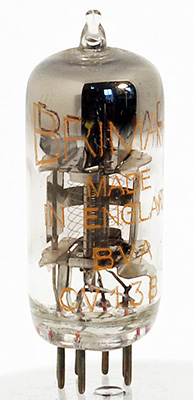
Comparing the X138 with the USA type 6AG5 which preceded it, it is notable how visible the internal parts are in the complete valve - the 6AG5 has a complex box around and obscuring its grids, its contempories (see appendix 1) also have the interior obscured. Much easier to see defects even at a late stage in production and easier for parts to radiate heat direct to the envelope.
- The X138 control grid bars have a separator plate at the top to fix the spacing, which also serves for radiant cooling.
- X138 has wider and longer anodes, accounting for its higher anode wattage rating, in fact all electrodes appear longer including the cathode.
- Despite the increased anode size of the X138, it has about half the g1 to anode capacitance of the 6AG5.
- The metal top hat in the X138 keeps any material from the getter away from the grids or micas reducing causes of insulation leakage or spurious emission. It also locates g3, the suppressor grid.
- With its g3 pin available and specification it could easily replace its predecessors SP61 or EF50 in television or radar equipment, using the same circuitry. Although a second cathode pin could have extended its usefulness to 400 MHz, it was good enough at 50 - 100 MHz, covering most applications.
Appendix 4 compares X138 examples found with CV138 specification and shows they fit that specification. That they may be prototypes is suggested by:-
- Anodes are bright finish, rather than blackened nickel which radiates heat much better - they overheat at CV138 anode Watt ratings - dimensions are same as later equivalents EF91 etc. This would not have mattered for evaluation of characteristics.
- Tabs at top of anode not turned over onto mica, although this cuts clearance to screen above.
- Heater wires are not as short, straight or well insulated as is usual.
- Button base and join to stem glass seems more like original RCA B7G types of 1940 than 1950s production of commercial versions.
- Envelope glass is clear without any coating.
It is noted that top micas are covered by metal shield and the top hat covers the grids - this protects both from contamination by getter blast which could cause insulation leakage or grid emission.
Appendix 1 - Notes on American B7G Valves
The article in RCA Review, April 1940 pp 375-381 introduces the new B7G valve base for miniature 1.4 V filament valves types 1R5, 1T4, 1S5, 1S4 to allow smaller battery powered portable equipment, such as a 4 valve superhet. The article shows that the electrodes have the same length and spacings as existing valves in octal base GT form, except the anode was made cylindrical to fit the small tube. Also most existing manufacturing fixtures & machinery (for International Octal valves) could be used with little modification.
Type 9001 RCA spec sheet July 1st 1941 - indirectly heated valve on the B7G base. Very small electrodes & current (Ia 2 mA) - re-package of 954 Acorn valve, which had awkward side-mounted pins, top & bottom caps and large base to mate them.
Type 6AG5 - 2 cathode pins - no g3 pin. Registered by RCA Sep 1942. In 1944 CV valve list as CV848 JAN. Used in AN/APS-13 Warning Radar year 1945. Oblong bright screen box obscures grids except through rectangular holes facing anodes. In fact, although called a pentode, the 6AG5 does not appear to have a suppressor grid & the complicated box looks like a beam tetrode arrangement, which avoided the Philips patents on the pentode with suppressor grid.
6AK5 also 2 cathode pins - no g3 pin. Also 1942 genesis. In 1944 CV valve list as CV850 JAN. Very small electrodes; grids visible only through round holes in anodes. Does not have the screen box of 6AG5.
RCA RC15 Tube Data Manual 1947 lists only the following sharp cut-off indirectly-heated pentodes - 6AG5, 6AK5, 6AU6 (separate g3 pin, same gm as 6AG5 but at much higher anode current, sharper cut-off; anode hides internal structure), 12AW6 (12 Volt heater, characteristics as 6AG5, but separate pin for g3), 9001 (B7G version of Acorn valve). Additionally 6BA6, 6BJ6 & 9003 are listed, but these are remote cut-off, with variations of pin-out.
6AH6 (1947?) GE - has bright metal screen around grids, like 6AG5.
Appendix 2 - Extract from Page 180, Bell System Technical Journal January 1957
Article on electron tubes for the First Transatlantic Telephone Cable (TAT-1, 1956) ref. UK made sections.
During the years 1944 and 1945 a very successful miniature high slope pentode, the CV138, was produced for the armed services. The electrical characteristics of this tube were superior to those of the SP61 and, in addition, it used a 2 Watt cathode. It was therefore decided to base the replacement tubes, electrically, on the CV138, whilst, at the same time, retaining freedom to amend the mechanical features in any way which might seem to favour the specific requirements of submerged repeater usage, in particular, maintenance of the level of transconductance unchanged for long periods.
Appendix 3 - Extract from the supplement to the Bulletin of the British Vintage Wireless Society ISSN 0955-9345
The early years of Ediswan and Mazda, Brian Munt, BVWS Bulletin Volume 16 Dec 1991 pp 7-13.
On page 9, RHS middle, there is ref. to Mazda Brimsdown factory (1938) & on page 11, last para.; 'All-glass miniature valves were produced at Brimsdown, during the war, using B7G 7-pin button bases'.
Appendix 4 - Characteristics of Mazda X138/V888 Samples vs CV138 Specification.
Item d, g of CV138 specification, anode/screen current with anode & screen 250 V and 160 Ω cathode bias resistor Rk.; Vh = 6.30 V. Test Rk actually 158.5 Ω.
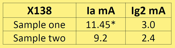
* The anode of sample one is all red hot at this power - pin 5 is anode pin, so has short conduction path to the socket, this anode stays black. Both samples have bright anode finish, while black finish is normal for EF91, 6AM6, Z77 etc. commercial equivalents to CV138. Black finished nickel has 3 times the emissivity e of bright (radiant heat loss factor e times K+4 dominates Watts loss at K degrees Kelvin, unless bulb temperature greatly exceeds 150 Celsius typical maximum). Sample two; anode is very dull red at 9.2 mA.
Item e of spec. conditions as d, g Reverse grid 1 current 0.5 μA maximum.
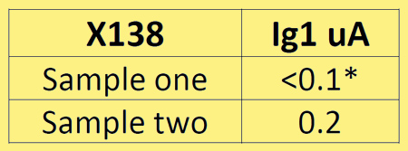
* 0.1 μA is the lowest reading of DMM.
Item h of CV138 specification, g1 cut-off -8 V maximum for anode current 100 μA with 250 V on g2 & anode. Got -5V for X138 No.2.
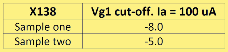
Conditions for the above test: Va = Vg2 = 250 V.
Item j of CV138 specification, g3 cut-off for anode current 50 μA with 250 V on g2 & anode and g1 at -3.5 V = -70 to -120 Volts (hence mean value -95 volts).
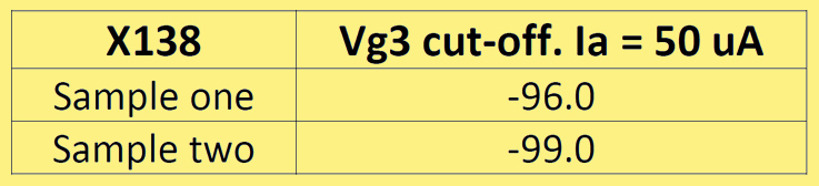
Conditions for the above test: Va = Vg2 = 250 V. Vg1 at -3.5 = -70 to -120 Volts (hence mean value of -95 Volts).
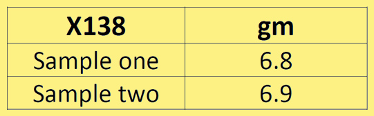
Item f of CV138 specification, mutual conductance minimum 6.0 mA/V, conditions as d, g above, results obtained for anode current increase of 2 mA approximately. Achieved by reducing cathode bias resistance.
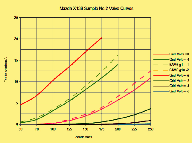
Curves for sample No.2 tested strapped as a triode, published curve for STC 6AM6 added for comparison.
|