|
Electron tubes for use in repeatered underwater telephone cable systems must be capable of operating for many years with a reasonable probability of proper functioning. In the new transatlantic telephone cable system the section of the cable between Nova Scotia and Newfoundland contains repeaters developed by the British Post Office Research Station at Dollis Hill. These repeaters are built around the type 6P12 tube developed at that research station. The repeaters contained in the section of the cable system between Newfoundland and Scotland are of Bell System design and depend on the 175HQ tube developed at Bell Telephone Laboratories.
In this paper the philosophy of repeater and tube design is discussed, and the fundamental reasons for arriving at quite different tube designs are pointed out. Some of the tube development problems and the features introduced to eliminate potential difficulties are described. Electrical characteristics for the two types are presented and life test data are given. Fabrication and selection problems are outlined and reliability prospects are discussed.
Introduction
Electron tubes suitable for use in long submarine telephone cables must meet performance requirements that are quite different from those imposed by other communication systems. In the home entertainment field, for example, an average tube life of a few thousand hours is generally satisfactory. In the field of conventional land-based telephone equipment, where the replacement of a tube may require that a maintenance man travel several miles, an average life of a few years is considered reasonable. In deep-water telephone cables such as the new transatlantic system, the lifting of a cable to replace a defective repeater may cost several hundred thousand dollars and disrupt service for an extended period of time. These factors suggest as an objective for submerged repeaters that the tubes should not be responsible for a system failure for many years, possibly twenty, after the laying of the cable. Such very long life requirements make necessary special design features, care in the selection and processing of materials that are used in the tubes, unusual procedures in fabrication, detailed testing and long ageing of the tubes, and the application of unique methods in the final selection of individual tubes for use in the submerged repeaters.
As indicated in the foreword and discussed at length in companion papers, the British Post Office developed the section of the cable system between Clarenville, Newfoundland, and Sidney Mines, Nova Scotia. This part of the transatlantic system uses the 6P12 tube which was developed at the General Post Office (GPO) Dollis Hill Research Station. The submerged portion of this system contains 84 tubes in 14 repeaters. Bell Telephone Laboratories developed the part of the system between Clarenville, Newfoundland, and Oban, Scotland. This section requires 102 repeaters, including 306 tubes, of a type known as the 175HQ. Although a common objective in the development of each of the two sections has been to obtain very long life, the tube designs are quite different.
The Bell System decided on the use of a repeater housing that could be treated as an integral part of the cable to facilitate laying in deep Avater. The housing is little larger than the cable and is sufficiently flexible to be passed over and around the necessary sheaves and drums. In such a housing the space for repeater components is necessarily restricted. This space restriction, combined with the general philosophy that the number of components should be held to an absolute minimum and that each component should be designed to have the simplest possible structural features, has resulted in the choice of a three-stage, three-tube repeater. In this design, each tube carries the entire responsibility for the continuity of service.
The Post Office Research Laboratories, prior to the development of the transatlantic cable system, had concentrated their efforts on shorter systems for shallow water. The placing of the repeaters on the bottom did not present the serious problems of deep-sea laying, so more liberal dimensions could be allowed for the repeater circuit. A three-stage amplifier was developed which consisted of two strings of three tubes each, parallel connected, with common feedback. The circuit was so designed that almost any kind of tube failure in one side of the amplifier caused very little degradation of circuit performance. This philosophy of having the continuity of service depend on two essentially independent strings of tubes has been carried over to the repeater design for the Clarenville- Sidney Mines section of the transatlantic cable.
In the Post Office system containing 84 tubes in the submerged repeaters, five tube failures randomly occurring in the system will result in slightly over fifty per cent probability of a system failure; one tube failure in the 306 tubes in the Newfoundland-Scotland section of the system will result in certain system failure. It is not surprising, therefore, to find the tube designed for the Newfoundland-Scotland section of the cable to have extremely liberal spacing between tube elements in order to minimize the hazards of electrical shorts. This results in a lower transconductance than is found in the tubes designed for the Nova Scotia- Newfoundland link. Other factors in the design will be recognized as reflecting the different operating hazards involved.
Early models of the British Post Office and Bell Laboratories tubes, together with the final tubes used in the cable system, are shown in Fig. 1.
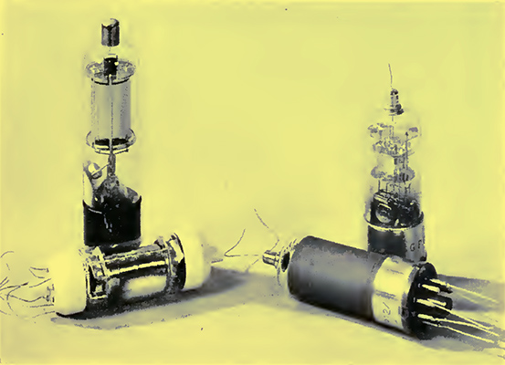
Fig. 1 b The final designs of tubes for the Nova Scotia-Newfoundland section of the cable (right) and for the Newfoundland-Scotland section (left). Early models of each type stand behind the final models.
Early Development Considerations
In Bell Telephone Laboratories, work on tubes for use in a proposed transatlantic cable was started in 1933. This was preceded by a study of what type of tube would best fit the needs of the various proposed amplifier systems and by consideration of what might be expected to give the best life performance.
At the time this project was started, reasonably good tube life had been established for the filamentary types used in Bell System repeaters. Some groups of tubes had average lives of 50,000 or 60,000 hours (6 or 7 years) . Equipotential cathode tubes were not then used extensively in the plant, and there was no long life experience with them. However, there appeared to be no basic reason why inherently shorter thermionic life should be expected using the equipotential cathode and there were several advantages in its use. One was the greater freedom in circuit design afforded by the separation of the cathode from the heater. Also there was the possibility of operating the heaters in series and using the voltage drop across the heaters for the other circuit voltages. It was felt, in addition, that the overall mechanical reliability would be greater if the cathode were stiff and rigidly supported.
The first equipotential tubes made were triodes. They were designed for use in push-pull amplifiers wherein continuity of service might be retained in case of a tube failure. This circuit was abandoned in favour of a three tube, feedback amplifier that was the forerunner of the present repeater. The pentode was favoured over the triode for this amplifier for obvious reasons, and in 1936 the triode development was discontinued.
Early in the development of the tube three basic assumptions were made. These were, (a) that operation at the lowest practical cathode temperature would result in the longest thermionic life, (b) that operating plate and screen voltages should be kept low, and (c) that the cathode current density should be kept as low as practicable.
The first assumption, concerning the cathode temperature, was based on the observation of life tests on other types of tubes. While the data at the time of the decision were not conclusive, there was definite indication that too high a cathode temperature shortened thermionic life. Little was known about life performance in the temperature range below the values conventionally used.
The second assumption, concerning low screen and plate voltages, had not been supported by any experimental work available at the time of decision. Sixty volts was originally considered for the output stage; this value was later lowered when other operating conditions were changed. Subsequent results showed that in this range the voltage effects on thermionic life were relatively negligible.
The third assumption, that low cathode current density favoured longer thermionic life, affected the tube design by suggesting the use of a large coated cathode area. This implied the use of relatively high cathode power. It was decided early in the planning of the repeater that the voltage drop across the three heaters operated in series would be used to supply part or all of the operating plate and screen potentials. For a 60 Volt plate and screen supply, the heater voltage could be as high as 20 Volts. A quarter of an ampere was considered a reasonable cable current consistent with voltage limitations at the cable terminals. Thus 5.0 Watts were available for each cathode. With this power, a coated area of 2.7 square centimetres was provided. The value of the cathode current, the cathode area, and the inter-electrode spacings define the transconductance. Very liberal inter-electrode spacings were provided consistent with reasonable tube performance. The original design called for a spacing of 0.040 inch between control grid and cathode. This value was later reduced to 0.024 inch, and a satisfactory design was produced which gave 1,000 micro-mhos or one milliampere per volt at a cathode current drain of approximately 2.0 milliamperes. The resulting current density of approximately 0.7 milliampere per square centimetre is in sharp contrast with values such as 50 milliamperes per square centimetre used currently in tubes designed for the more conventional communication uses. Subsequent data, discussed later, indicate that for current densities of a few milliamperes per square centimetre, the exact value is not critical in its effect on thermionic life.
Subsequent Production Programs
The development of the tube was pursued on an active basis through the years leading up to World War II. During the war development activity essentially stopped. It was only possible to keep the life tests in operation. After the war the development of the tube was completed and a small production line was set up in Bell Telephone Laboratories under the direct supervision of the tube development engineers to make and select tubes for a cable between Key West, Florida, and Havana, Cuba.
This cable turned out to be a field trial for the transatlantic cable which was to come later. A total of G submerged repeaters containing 18 tubes were laid and the cable was put in operation in June, 1950. The cable has been in operation since this date without tube failure, and periodic observations of repeater performance indicate no statistically significant change in tube performance over the 6 years of operation.
Sufficient tubes were made at the same time as the Key West-Havana run to provide the necessary tubes for a future transatlantic cable. These tubes were never used principally because the tubes had been assembled with tin plated leads. Tin plating, subsequent to the laying of the Key West-Havana cable, was found to be capable of growing whiskers [1] K G Compton, A Mendizza and S M Arnold, Filamentary Growths on Metal Surfaces b Whiskers, Corrosion, 7, pp. 327-334, Oct. l951..
In 1953 another production setup was made, also in Bell Telephone Laboratories, for the fabrication of tubes for the Newfoundland-Scotland section of the transatlantic cable. On the completion of this job fabrication was continued to provide tubes for an Alaskan cable between Port Angeles, Washington, and Ketchikan, Alaska. After a pause of several months another run was made to provide tubes for a cable to be laid between California and the Hawaiian Islands.
Mechanical Features
The tube, shown on the left in Fig. 1, is supported in the repeater housing by two soft rubber bushings into which the projections of the two ceramic end caps fit. All leads are flexible and made of stranded beryllium copper which has been gold plated before braiding. Both for convenience in wiring in the circuit and to hold down the control-grid to anode capacitance, the grid lead has been brought through the opposite end of the tube from the other leads.
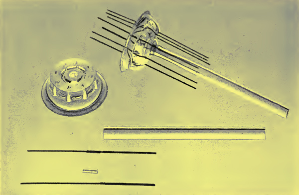
Fig. 2 - Parts used in the stem and a finished stem of the 175HQ tube. The separate beading of the leads may be noted.
A number of somewhat unusual constructional features appear in the tube. The stem on which the internal structure is supported consists of a moulded glass dish into which seven two-piece beaded Dumet leads are sealed. The parts used in a stem, and also a finished stem, are shown in Fig. 2. It is usual to embed the weld or knot between the Dumet and nickel portions of the lead in the glass seal to provide more structural stiffness. This has not been done in this stem because it was believed that a fracture of a lead at the weld could be detected more easily if it were not supported by the seal. It might be questioned why the modern alloys and fiat stem structure have not been used. It is to be remembered that one gas leak along a stem lead would disable the system, and experience built up with the older materials provides greater assurance of satisfactory seals.

Fig. 3 b Heater, heater insulator and cathode assembly of the 175HQ tube.
The structure of the heater and cathode assembly is unique, as may be seen in Fig. 3. A heater insulator of aluminium oxide is extruded with 7 holes arranged as shown. This insulator is supported by a 0.025 inch molybdenum rod inserted in the centre hole. The heater consisting of about 36 inches of 0.003 inch tungsten is wound into a helix having an outside diameter of 0.013 inch. After dip coating by well known techniques the heater is threaded through the 6 outer holes in the insulator. A suspension of aluminium oxide is then injected into the holes in the insulator so that on final firing the heater becomes completely embedded.
The cathode sleeve, which is necked down at one end as shown in Fig. 3, is sUpped over the heater assembly and welded to the central molybdenum rod which becomes the cathode lead. By this means a uniform temperature from end to end of the cathode is obtained. Under normal operating conditions the heater temperature is approximately 1,100°C, which is very considerably under the temperature found in other tubes.
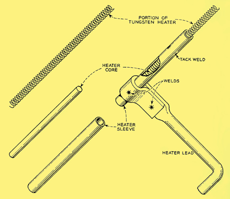
Fig. 4 b Heater tabbing arrangement of the 175HQ.
Connection of the heater to the leads from the stem presented a serious design problem. Crystallization of tungsten during and after welding and mechanical strains developed by thermal expansion frequently are the causes of heater breakage. This problem was successfully overcome by the means illustrated in Fig. 4. Short sections of nickel tubing are slipped over the cleaned ends of the heater coil and matching pieces of nickel wire are inserted as cores. These parts are held together by tack welds at the midpoints of the tubing. The heater stem leads are bent, flattened and formed to receive the ends of the heater, which are then fastened by welds as indicated in the drawing.
A serious attempt has been made in the design of the tube to hold the number of fastenings that depend entirely on one weld to an absolute minimum. The grids are of conventional form in which the lateral wires are swaged into notches cut in the side rods or support wires. The side rods as well as the lateral wire are molybdenum. This produces grids which are considerably stronger than those using more conventional materials.
The upper mica is designed to contact the bulb and the bulb is sized to accurate dimensions to receive and hold the mica firmly. The tube in its mounting will withstand a single 500 g one millisecond shock without apparent changes in mechanical structure or electrical characteristics. It is estimated from preliminary laying tests that accidental or unusual handling would rarely result in shocks exceeding 100 g.
Electrical Characteristics and Life
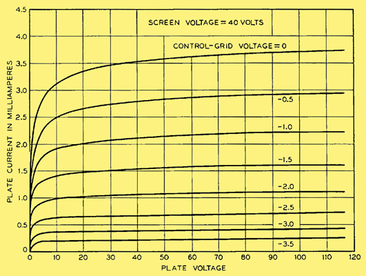
Fig. 5 b Typical plate voltage-plate current characteristics for a type 175HQ tube.
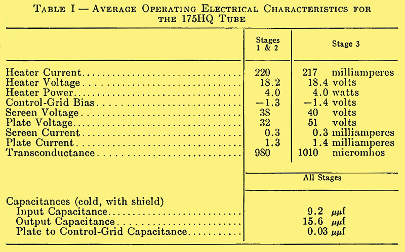
The average operating electrical characteristics for the 175HQ tube are given in Table I, and a family of plate-voltage versus plate-current curves for a typical tube is given in Fig. 5 for a region approximating the operating conditions.
The development of a long-life tube offers good opportunities to observe effects which are more likely to be missed where shorter lives are satisfactory. For example, some of the earliest tubes made, after 20,000 hours on the life racks, began to show a metallic deposit on the bulbs.
Immediate concern for the lowering of insulation resistance across mica spacers prompted an investigation. The source was traced to the use of plates made from a grade of nickel from which magnesium as a contaminant was evaporating. A change was made to molybdenum which has been used successfully since that experience.
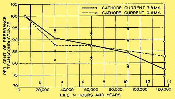
Fig. 6 - Results of life tests on eighteen 175HQ tubes operating at two different current densities.
The effect on the thermionic life of operating at different cathode current densities was of interest. Life tests were started in which the cathode current drain in one group of tubes was approximately 7.5 milliamperes (2.8 mA/cm2) and in another group the average cathode current was 0.6 milliamperes (0.2 mA/cm2). The results presented in Fig. 6 after 120,000 hours, or approximately 14 years, show that at the cathode temperature of approximately 710°C selected for the test. (All cathode temperatures referred to in this paper are true temperatures, not uncorrected pyrometer temperatures.) There is practically no current density effect in this 12 to 1 current range. The circles indicate average values, while the dots and crosses at each test point show the positions of the extreme tubes of the group.
Similar life tests set up to show the effect of operating at plate and screen voltages of 60 Volts as compared to 40 Volts indicate no essential differences in performance after 8 years of operation.
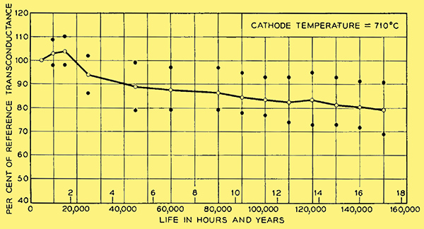
Fig. 7 - Results of life tests on sixteen 175HQ tubes operating at a cathode temperature of 710°C.
The cathode temperature is one of the most critical operating variables affecting thermionic life. As mentioned above, the early development objective was a cathode power of 5.0 watts which corresponded to 710°C for the cathode design used at that time. The results of operating at this condition are illustrated in Fig. 7. No tubes have been lost from the test Where the direct cause has been failure of emission. Several tubes were lost because of mechanical failure resulting from design defects which were subsequently corrected. It will be observed that at the end of 17 years the average transconductance is 80% of its original value, and the poorest tube has dropped to 69%. There is reason to believe that test set difficulties may very well account for a large part of the variation shown in the first three years.
The cathode coatings used in all experimental and final tubes for the Newfoundland-Scotland link of the transatlantic cable are the conventional double carbonate coatings. The cathode base material is an International Nickel 220 nickel. The particular melt used for the transatlantic cable is known as melt 84. A typical analysis for melt 84 nickel cathodes is given in Table II.
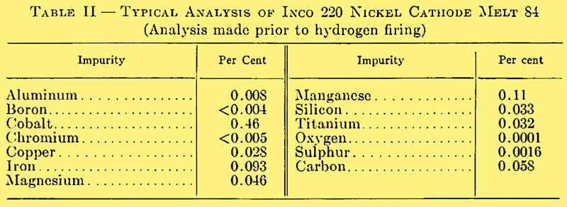
The relatively high carbon content (0.058%) of melt 84 cathode nickel is capable of producing excessive reduction of barium in the cathode coating. [2] M Benjamin, The Influence of Impurities in the Core-Metal on the Thermionic Emission from Oxide-Coated Nickel, Phil. Mag. and Jl. of Science, 20, p. 1, July, 1935. [3] H E Kern and R T Lynch, Initial Emission and Life of a Planar-Type Diode as Related to the Effective Reducing Agent Content of the Cathode Nickel (abstract only), Phys. Rev., 82, p. 574, May 15. 1951. A treatment in wet hydrogen, prior to coating, at 925°C for 15 minutes reduces the carbon in the cathode sleeve to about 0.013%.
Melt S4 was as close as was obtainable in composition to melts 60 and 03 previously used for the Key West-Havana tubes. The results of up to five years of life testing were thus available on materials of very similar composition.
One common cause of tube deterioration with life is the result of formation of an interface layer on the surface of the cathode sleeve. It is known that the rate of development of this layer depends in at complex way on the chemical composition of the nickel cathode core material. The effect of such a layer is to introduce a resistance in series with the cathode. This results in negative feedback and reduces the effective transconductance. Since the effect of a given feedback resistance in this location is proportional to transconductance, the relatively low value for the 175HQ tube tends to minimize this feedback effect. In addition, the low cathode temperature tends to reduce the rate of formation of interface resistance, and the relatively large cathode area tends to further minimize the effects. The final decision to use melt 84 was based on accelerated ageing tests which showed it to be superior to melts 60 and G3 from an interface standpoint.
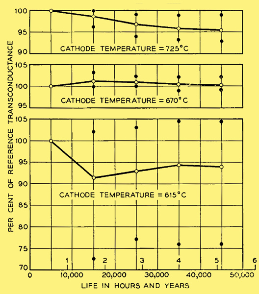
Fig. 8 - Results of operating thirty-six 175HQ tubes divided equally among three different cathode temperature conditions. For each of the curves the cathode core material used was half from melt 60 and half from melt 63. The conditions in cable operation are essentially those represented by the centre curve.
The interface problem will be discussed further in a later section. As the development of the tube proceeded, both the processing of the parts and the cleanliness of the mount assembly were improved and the cathode emission level increased. Life tests indicated that better thermionic life might be obtained by operating at a lower cathode temperature. Accordingly a cathode power of approximately 4.0 Watts was adopted, which corresponds to a temperature of 670°C. A life test, now 45,000 hours or about 5 years old, shows the results in Fig. 8 of operating groups of tubes at three different cathode temperatures. This is a well controlled test in that the tubes for the three groups were picked from tubes having common parts and identical fabrication histories. It may be noted that the average of the 725°C lot has lost approximately 5% of the initial transconductance, whereas the 4.0 Watt group after about 5 years has lost essentially none of its transconductance. The 3.0 Watt (610°C) group shows serious instabilities in its performance. In some of the tubes the cathode temperature has not been sufficiently high to provide the required emission levels.
The design of the repeaters in the Newfoundland-Scotland section of the cable is such that reasonably satisfactory cable performance would be experienced if the transconductance in each tube dropped to 65 per cent of its original value. The life test performance data presented in Figs. 7 and 8, and other tests not shown, indicate that operation of the 175HQ tubes in the transatlantic cable at approximately 4.0 Watts will assure satisfactory thermionic performance for well over 20 years.
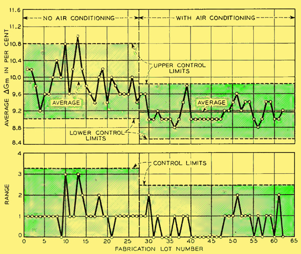
Fig. 9 - Control chart showing the effect of air cleaning on the cathode activity level. The per cent change in transconductance for normal heater current and a value 20 per cent lower is used as the measure of cathode performance.
Mention was made that cleanliness in the assembly of the mounts was a factor which affected thermionic activity. Interesting evidence supporting this view was obtained during the fabrication of tubes for the Key West-Havana cable. The quality control type of chart reproduced in Fig. 9 shows the average change in transconductance between two set values of heater current for the first 5 tubes in each group of approximately 28 tubes made. The data were taken after 5,000 hours of ageing. A sharp improvement in thermionic emission was noted at a point on the chart where about one half of tubes had been fabricated. An examination of the records, which are very carefully maintained, disclosed that the windows of the assembly room were sealed and air cleaning and conditioning was put in effect at the point indicated on the chart. No other changes in processing or materials occurred at this time. A second definite improvement in thermionic emission occurred when the work was moved from the location in New York City to the new and better controlled environment at Murray Hill in New Jersey.
Fabrication and Selection
All assembly operators on the 175HQ tube program wore nylon smocks to keep down the amount of dust and lint that might otherwise leave their clothing and get into the tubes. Rayon acetate gloves were worn when handling parts as a protection against perspiration. Rubber finger cots did not prove satisfactory because they covered too little area and once contaminated they did not absorb the contaminant.
The tubes for the Newfoundland to Scotland section of the cable were made at Bell Telephone Laboratories under the extremely close engineering supervision of many of the original development engineers. All materials going into the tubes were carefully checked, and wherever possible they were tried out in tubes. Experience under accelerated ageing conditions was obtained before these materials were used. For example, although during the development period all glass bulbs were used as received without any failures resulting, less than one-quarter of the bulbs bought for the actual cable job passed the inspection requirements. Each batch of heaters was sampled and results obtained on intermittent and accelerated tests before approval for use.
The fabrication of the tube was carried out with extreme care by operators especially selected for the job. If normal commercial test limits were applied to the tubes after exhaust, the yield from acceptable mounts would have been about 98 to 99 per cent. Yet only approximately one out of every seven tubes pumped was finally approved for cable use. All tubes were given 5,000 hours ageing and electrical tests were made at six different times during this period. The results weighed heavily in the final selection. For example, a correlation between thermionic life and gas current had been established during the tube development period, and only tubes having control-grid currents due to gas of less than 5 X 10-11 ampere were acceptable. This corresponds to a gas pressure of approximately 2 X 10⁻⁷ mm of Hg. Very thorough mechanical inspections after the 5,000-hour ageing were made to insure that there were no observable mechanical deviations that could cause trouble. The history of each group of 28 tubes, from which prospective candidates for the cable were selected, was reviewed to see if any group abnormalities were found. In case a suspected trait was seen, all tubes in the group were ruled out for cable use.
As an aid in the selection of tubes for the cable, all pertinent data were put on IBM cards. It was then possible to manipulate and present the data in many very helpful ways that would have otherwise been wholly impractical from time and manpower considerations. An over-all total of about half a million bits of information was involved.
Reliability Prospects
Questions are frequently raised concerning the probability of tube failures in the system. There are two areas into which failures naturally fall - catastrophic failures and the type of failure caused by cumulative effects such as the decay of thermionic activity, development of primary emission from the control-grid, or the build-up of conductance across mica insulators or glass stems.
The catastrophic failures might include such items as open connections caused by weld failures or fatigue of materials, short circuits caused by parts of two different electrodes coming into contact or being bridged by conducting foreign particles and gas leaks through the glass or along stem leads. Fortunately these failure rates have been lowered to a point where there are no sound statistical data available in spite of the substantial amount of life testing that has been done. In approximately 4,800 tubes made to date, there have been four failures that were not anticipated by the inspections made. All four of these failures were of different types and occurred either at or before 5,000 hours of life. All four were of types more apt to occur during the early hours of ageing and handling.
Of the cumulative types of failure, life testing has indicated no apparent problem with either the growth of insulation conductance or primary emission from the grids. As indicated earlier in the paper, thermionic life results are such that there is reason to be optimistic that no failures will occur in 20 years.
Tubes for the Nova Scotia-Newfoundland Cable
Trend of Tube Development in British Submarine Repeater Systems
Early Use of Commercial Receiving Tubes
The development of submerged telephone repeaters in Britain has taken a somewhat different course from that followed in the United States. Off North America, deep seas are encountered as soon as the continental shelf has been passed. Consequently emphasis has been placed from the beginning on the design of repeaters for ocean depths. In Britain, separated from many countries by only shallow seas, it was natural for development to start with a repeater specially designed for shallow water. Such a repeater was laid in an Anglo-Irish cable in 1944.
The tubes used in the amplifier of this repeater were normal high transconductance commercial pentodes type SP61 [§] Mazda advertise the SP41 as the valves used. See the link in the extras menu.. These tubes were known, from life test results, to last at least for two years under conditions of continuous loading. Their performance in the first and subsequent early repeaters exceeded all expectations. So far one tube has failed, and this from envelope fracture, after a period of four years service. There remain 23 of this type on the sea bed with a service life of five or six years, and 3 tubes which have survived ten years.
All these SP61 tubes were part of a single batch made in 1942 and their performance set a high standard. It was, however, found that subsequent batches did not attain the same standard set by the 1942 batch. In 1946, therefore, the British Post Office was faced with the fact that future development of the shallow water system of submerged repeaters was dependent on the production of a tube type which could take the place of the 1942 batch of SP61 tubes. This situation led to the formation of a team at Dollis Hill whose terms of reference were, specifically, to produce the replacement tube and, generally, to study the problems presented by the use of tubes in submerged repeaters. Apart from changes in the specific requirements, these terms of reference have remained unchanged from that day to this.
Replacement by the GPO 6P10 Type
Coincident with the rapid exhausting of stocks of satisfactory SP61 tubes for submerged telephone systems, there arose the need for a tube type for a submerged telegraph repeater. This latter requirement was complicated by the fact that the telegraph cable was subject to severe overall voltage restrictions which precluded the 630 mA heater current required for the 4 Watt cathode of the SP61. In order to avoid production of one tube type for telephone systems and another for telegraph, it was decided that the replacement for the SP61 should have a 2 Watt cathode with a 300 mA heater.
During the years 1944 and 1945 a very successful miniature high slope pentode, the CV138, was produced for the armed services. The electrical characteristics of this tube were superior to those of the SP61 and, in addition, it used a 2 Watt cathode. It was therefore decided to base the replacement tubes, electrically, on the CV138, whilst, at the same time, retaining freedom to amend the mechanical features in any way which might seem to favour the specific requirements of submerged repeater usage, in particular, maintenance of the level of transconductance unchanged for long periods. Consequently three major mechanical changes were made at the outset of the project. The miniature bulb of the CV138 was replaced by one of normal size (approximately 1 inch diameter and 2.5 inches long). This was done to reduce the glass temperature and so reduce gas evolution. At the same time a normal press and drop seal were substituted for the button base and ring seal of the CV138, as it was felt that, with the techniques available, the former would be more reliable than the latter. With the use of a normal press there immediately followed a top cap control grid connection, so producing a double-ended tube in place of the single-ended CV138.
These three modifications and a number of major changes to improve welding and assembly techniques led to the GPO type known as the 6P10 (A pentode with a 6.3 Volt heater of design mark 10). The 6P10 replaced the SP61 in the 18 shallow water repeaters laid in various cables after 1951. There are, therefore, 54 tubes type 6P10 in service on the sea bed with periods of continuous loading ranging from two to four years. There has been one failure due to a fractured cathode tape, and one other repeater was withdrawn from service to investigate a high frequency oscillation associated with a tube. The oscillation cleared, however, before the cause could be identified.
The first eighteen 6P10 type tubes used in repeaters had conventional nickel cathode cores. Appreciation of the problem of interface resistance led to the use of platinum as a core material for the following 36 tubes. The steps leading to this radical change of technique will be described later.
Development of the 6P12 for Long Haul Systems
Although .submerged repeater development started naturally in Britain with shallow-water systems, it was inevitable that attention should ultimately turn towards trans-ocean cables. The tube requirements for such long haul systems differ from those for short haul shallow-water schemes in that operation at a lower anode voltage is essential. A new tube to replace the 6P10 was therefore unavoidable.
By the time emphasis started to shift in Britain from shallow-water to deep-sea systems some considerable experience had been gained at Dollis Hill on the production techniques required to fit a 6P10 type tube having a platinum cathode core for submerged repeater usage. When it became apparent that a new tube had to be designed for the first long haul system, it was resolved to retain as much as possible of the 6P10 structure in order to take full advantage of familiar techniques. The 6P10 was therefore redesigned for 60 Volt operation simply by a major adjustment to the screen grid position and minor alterations elsewhere. The new tube became known as the 6P12 and was used in seven repeaters installed in the Aberdeen-Bergen cable. This scheme was regarded as a proving trial for the Newfoundland-Nova Scotia section of the transatlantic project.
It has always been appreciated that the use of high transconductance tubes using closely-spaced electrodes will involve a higher liability to mechanical failure by internal short circuits. Practical experience in shallow-water schemes, where repeater recovery is a comparatively cheap and simple operation, has shown however that such risks seem to be outweighed by the economic advantage accruing from a tube capable of wider frequency coverage. In point of fact a failure by internal short circuit has not yet materialized on any shallow-water system.
This background of experience explains the British choice of a high transconductance tube for deep-sea systems, but the greater liability to mechanical failure is acknowledged by use of parallel amplifiers. Confidence in this policy has been increased by the successful operation of the Aberdeen-Bergen system.
Problems of Development of the 6P12 Tube
The main preoccupation of the thermionics group at Dollis Hill since 1946 has been a study of the electrical life processes of high transconductance receiving tubes. This effort has led to a conviction that all changes of electrical performance have their origin in chemical or electro-chemical actions occurring in the tube on a micro- or milli-micro scale of magnitude. The form of change of most importance to the repeater engineer is decay of transconductance and this will be considered in brief detail as typical of the development effort put into the 6P12 tube.
Transconductance decay in common tubes results from two separate and distinct chemical actions occurring in the oxide cathode itself. Both actions are side issues in no way essential to the basic functioning of the cathode and it seems probable that both can be eliminated if sufficient understanding of their nature is available. The first action is the growth of a resistive interface layer between the oxide matrix and its supporting nickel core, discussed briefly in an earlier section. This effect is assumed to be due to silicon contamination of the nickel core metal.
4 BaO + Si = Ba2Si04 + 2 Ba.
The resistance of the layer of barium orthosilicate rises as it loses its barium activator and approaches the intrinsic state. The effect of the interface resistance is to bring negative feedback to bear on the tube with resulting loss of transconductance. The second deleterious action is loss of electron emission from the oxide cathode by direct destruction of its essential excess barium metal by oxidizing action of residual gases. Such gases result from an imperfect processing technology.
These two problems have been approached in the 6P12 tube in a somewhat novel manner. The conventional nickel core is replaced by platinum of such high purity (99.999 per cent) that the possibility of appreciable interface growth from impurities can be disregarded. The only factor to be considered is the appearance of high resistive products of a possible interaction between platinum and the alkaline earth oxides. Batch tests over a period of 30,000 hours have failed to show any sign whatever of such an action occurring and workers at Dollis Hill now regard the pure platinum-cored tube as free from the interface resistance phenomenon.
The problem of avoiding gas deactivation of the cathode is a more difficult one and so far has been reduced in magnitude rather than eliminated. It is now appreciated that the dangerous condition arises from gas generators left in the tube and not from a true form of residual gas pressure left after seal-off from the pump. These gas generators are solid components of the tube which give off a continual stream of gas over a prolonged period of time. The gas evolution rates are usually so small that they cannot be detected by reverse grid current measurement but they tend to integrate gas by absorption on the cathode and to destroy its activity. The gas generators are usually of finite magnitude and, depending mainly on diffusion phenomena, evolve gas at a rate which falls in roughly exponential fashion with time. The probability of trans-conductance failure is therefore highest in early life and tends to lessen with time as the generators move to exhaustion.
One particularly useful feature of the platinum-cored cathode is its freedom from core oxidation during gas attack and this leaves the tube free to recover from transconductance failure when the gas attack has passed. In Fig. 10 is shown the behaviour of a group of 50 tubes which have been deliberately left in possession of a component capable of generating carbon-monoxide over a prolonged period of time. The curve shows the characteristic recovery of a platinum-cored oxide-cathode With the gradual passing of what is thought to be a typical gas attack.
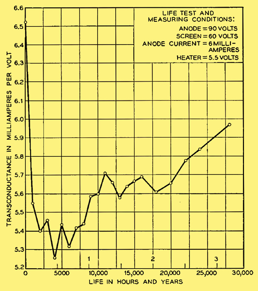
Fig. 10 - Behaviour of a group of 50 tubes deliberately left with a gas generator (tube type 6P12).
One problem that has attracted much attention at Dollis Hill is the actual manner in which a platinum-cored cathode recovers from a gas attack. The mechanism must involve the dissociation of a small fraction of the oxide cathode itself with the retention of barium metal in the oxide lattice and the evolution of oxygen. That such an essential mechanism does in fact exist has been proved by the slow accumulation of barium metal in the platinum core. This accumulation takes the form of a distinctive alloy of barium and platinum and only occurs when the cathode is passing current. The barium regenerative process seems therefore to be electrolytic in nature and, depending only on current flow and a stock of oxide, would appear to be virtually inexhaustible.
These few remarks are perhaps sufficient to give some idea of the lines on which the British research effort has run during the past decade. More detailed descriptions have already been presented elsewhere. [4] G H Metson, S Wagener, M F Holmes and M R Child, The Life of Oxide Cathodes in Modern Receiving Valves, Proceedings IEE, 99, Part III, p. 69, March, 1952. [5] G H Metson and M F Holmes, Deterioration of Valve Performance Due to Growth of Interface Resistance, Post Office Electrical Engineers Journal, 46, p. 193, Jan., 1954. [6] M R Child, The Growth and Properties of Cathode Interface Layers in Receiving Valves, Post Office Electrical Engineers Journal, 44, p. 176, Jan., 1952. [7] G H Metson, A Study of the Long Term Emission Behaviour of an Oxide Coated Valve, Proceedings IEE, 102, Part B, p. 657, Sept., 1955.
Electrical and Mechanical Characteristics
Electrical Characteristics
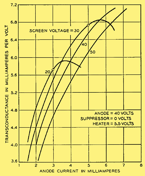
Fig. 11 - Typical transconductance-anode current characteristics for a type 6P12 valve (No. 457/6).
The main electrical characteristics of the 6P12 are shown in Figs. 11 and 12. The heater voltage used for both sets of curves is 5.5 Volts, the same value as that used in the British amplifier. Fig. 11 shows the change of transconductance with anode current, with screen voltage as parameter. An anode voltage of 40 Volts and a suppressor voltage of zero correspond with the static operating conditions in the first two stages of both the Aberdeen-Bergen and the British transatlantic telephone (TAT) amplifiers. The screen voltage and anode current of the first two stages of the British TAT amplifier were chosen to be -10 volts and 3 mA respectively.
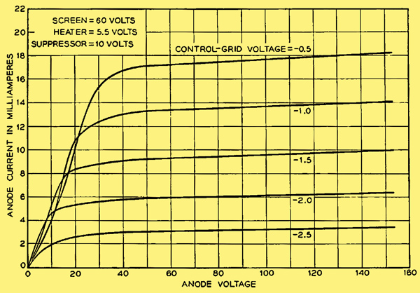
Fig. 12 - Typical anode voltage-anode current characteristics for a type 6P12 valve (No. 457/6).
Fig. 12 shows the normal anode voltage-anode current characteristics for conditions corresponding to the output stage of the amplifier (static operating point, anode voltage = 90, screen voltage = 60, anode current = 6 mA). A final electrical characteristic worthy of comment is the level of reverse grid current. For all specimens tested at the time of selection, after about 4,000 hours life test, the level is very low, about 100 micro-micro-amperes per milliampere of anode current.
Life Performance
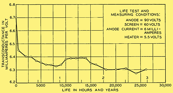
Fig. 13 - Behaviour of a group of 92 type 6P12 tubes over a period of three years.
The life performance of the 6Pl2 is still a matter for conjecture. The only concrete evidence available is the behaviour of a group of 92 tubes which were placed on life test some three years ago. The change of the average transconductance of this group (with anode current constant at 6 mA) is shown in Fig. 13. It may be clearly appreciated that there is no definite trend over the past year which permits any firm prediction of life expectancy. Examination of other tube characteristics is equally unproductive from the point of view of prediction of failure.
In the early stages of the test there were eight mechanical failures. The cause in all instances was identified and corrected in subsequent production before the start of the TAT project.
Mechanical Characteristics
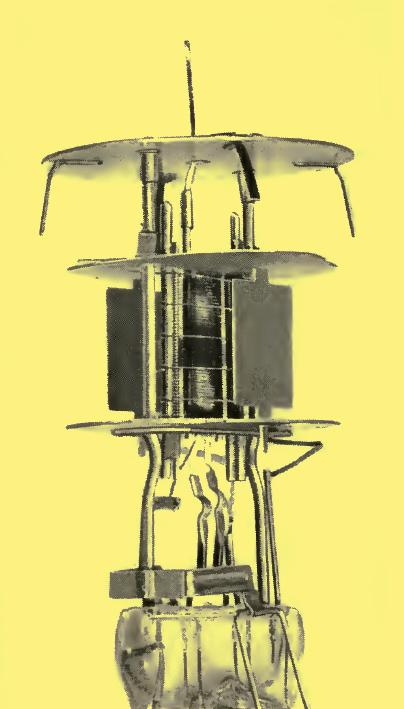
Fig. 14 - View of interior of a 6P12 type tube.
The chief mechanical characteristics of the 6P12 have been mentioned before in that they are, as explained, very similar to those of the 6P10. A photograph of the interior of the tube is shown in Fig. 14.
Valve Selection Techniques
Not all the valves, found after production to be potentially suitable for the British TAT amplifier, remained equally suitable after the life test period of about 4,000 hours. A brief account of how the best were selected is given below.
The fact that every tube had to pass conventional static specification limits needs little emphasis here. This test was, however, supplemented by three additional types of specification. First, every tube was tested in a functional circuit, simulating that stage of the amplifier for which the tube was ultimately intended. Here measurements were made of shot noise (appropriate to first stage usage) and harmonic generation (appropriate to the output stage) in addition to the usual measurements of transconductance, anode impedance and working point.
Second, all tubes were subject to intensive visual scrutiny in which some 80 specific constructional details were checked for possible faulty assembly.
Third, the life characteristics of transconductance, total emission and working point were examined over the test period of about 4,000 hours for unsatisfactory trends. Although this type of specification is more difficult to define precisely, its application is probably more rigorous and exacting than any of the previous specifications.
Only if a tube passed the conventional test and the three supplementary tests was it considered adequate for inclusion in a repeater.
Conclusion
The laying of the present repeatered transatlantic cable represents by far the most ambitious use to date of long life, unattended electron tubes. On this project alone there are 390 tubes operating on the ocean bottom. If to this number are added the ocean bottom tubes from earlier shorter systems, those used in the Alaskan cable completed a few months ago, and those to be used in the California-Hawaiian cable to be laid in 1957, the total number on the ocean bottom will be about one thousand. The capital investment dependent on the satisfactory performance of these tubes is probably about one hundred million dollars b strong evidence of faith in the ability to produce reliable and trustworthy tubes.
It is of interest to note that the two groups working on the tubes on opposite sides of the Atlantic had no intimate knowledge of each other's work until after the tube designs had been w^ell established. As a result of subsequent discussions, it has been surprising and gratifying to find how similarly the two groups look at the problems of reliability of tubes for submarine cables.
The authors would be completely remiss if they did not mention the contributions of others in the work just described. These projects would have been impossible if it were not for the enthusiastic, cooperative and careful efforts of many people working in varied fields. Over the years chemists, physicists, electrical and mechanical engineers, laboratory aides, shop supervisors and operators all have made essential contributions to the projects. It would be impractical and unfair to attempt to single out for mention the work of specific individuals whose contributions are outstanding. There are too many.
References
- K G Compton, A Mendizza and S M Arnold, Filamentary Growths on Metal Surfaces b Whiskers, Corrosion, 7, pp. 327-334, Oct. l951.
- M Benjamin, The Influence of Impurities in the Core-Metal on the Thermionic Emission from Oxide-Coated Nickel, Phil. Mag. and Jl. of Science, 20, p. 1, July, 1935.
- H E Kern and R T Lynch, Initial Emission and Life of a Planar-Type Diode as Related to the Effective Reducing Agent Content of the Cathode Nickel (abstract only), Phys. Rev., 82, p. 574, May 15. 1951.
- G H Metson, S Wagener, M F Holmes and M R Child, The Life of Oxide Cathodes in Modern Receiving Valves, Proceedings IEE, 99, Part III, p. 69, March, 1952.
- G H Metson and M F Holmes, Deterioration of Valve Performance Due to Growth of Interface Resistance, Post Office Electrical Engineers Journal, 46, p. 193, Jan., 1954.
- M R Child, The Growth and Properties of Cathode Interface Layers in Receiving Valves, Post Office Electrical Engineers Journal, 44, p. 176, Jan., 1952.
- G H Metson, A Study of the Long Term Emission Behaviour of an Oxide Coated Valve, Proceedings IEE, 102, Part B, p. 657, Sept., 1955.
|