|
Another application of the Transition or negative transconductance oscillator.
This article describes theoretical and practical work to demonstrate the close analogy between the Herold 'negative transconductance' oscillator and the two-valve Franklin or multivibrator oscillator, and shows how the negative transconductance oscillator, like the multivibrator, may be used as a frequency divider.
It has been customary to call the negative transconductance oscillator the Transitron, but since no use is actually made of any transit time phenomenon the name is rather unfortunate. Throughout the present paper the arrangement will be referred to as the Herold oscillator, since it is believed that the first published reference to an oscillator of this type was made under E W Herold's name [1] Negative Resistance and Devices for Obtaining It, E W Herold, Proc. IRE, Oct. 1935..
Negative Transconductance Effect
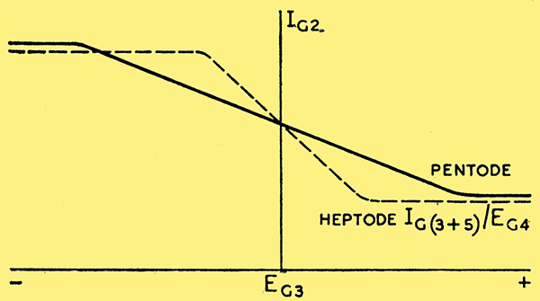
Fig. 1. Negative transconductance effect in pentode and heptode valves.
If a normal pentode has its inner or working grid G1 returned to cathode or to some value of fixed bias it tends to set a limit to the total cathode current (providing no large change of screen voltage EG2 occurs) and the suppressor potential will determine how this limited cathode current is divided between the anode and the screen. With a high negative potential on the suppressor grid G3 the anode current is cut off and all the cathode current flows to the screen G2. As this negative potential is reduced there is no change in G2 current until a point is reached when anode current starts to flow, and since no increase in cathode current is possible the G2 current falls. The period of falling screen current Ig2 lasts until G3 is somewhere in the positive region and all electrons passing through G2 are accelerated onwards. IG2 has then fallen to a value determined by the number of electrons colliding with the G2 structure and no further reduction in IG2 can occur. The theoretical characteristic is therefore as shown in Fig. 1, and it will be noted that over the centre range this is the inverse of a normal triode Ia/Eg curve.
This characteristic is even more pronounced in the case of a heptode, in this case the G1 (oscillator grid) and the G2 (oscillator anode) are returned to cathode and the inverted characteristic appears between G4 (signal grid) and the G3 plus G5 screen. The reason for the higher negative slope is that the signal grid of a heptode is wound with a much closer pitch than the suppressor of a pentode and the limiting conditions occur with considerably less positive or negative potential (Fig. 1). A triode hexode also shows this effect but the triode grid strapped internally to the G3 grid modifies its application considerably; this point will be dealt with more fully later on.
The heptode does not show as great an increase of slope as it might. The screen current consists of two parts, that which flows from G3 exhibiting the negative slope characteristic, while that from G5 exhibits a normal positive slope similar to that of the anode. The nett screen current is determined by the difference between these two characteristics and the value of. the negative slope is not as high as it could be. A valve with the two parts of the screen brought out separately would show a further increase in negative slope, and, as will be mentioned later on, would have a further important advantage.
Analogy Between Franklin and Herold Oscillators
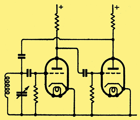
Fig. 2. Franklin two-valve oscillator.
In order to secure oscillations in a circuit associated with a triode valve it is necessary to feed back from the anode circuit a potential that is in phase with the grid voltage, and since the anode and grid potentials are normally in opposite phase, some external means must be found of securing additional phase reversal in the feedback path. In most single valve oscillators this is achieved by a second winding or a tapping point on the coil. A second valve may be used, however, to obtain this phase reversal, and the result is the well-known Franklin oscillator (Fig. 2).
Since the pentode valve used as described above has an EG3/IG2 characteristic which is the reverse of a normal triode Ia /Eg characteristic no external phase reversal is necessary, and oscillation is secure by coupling straight back from G2 (Fig. 3).
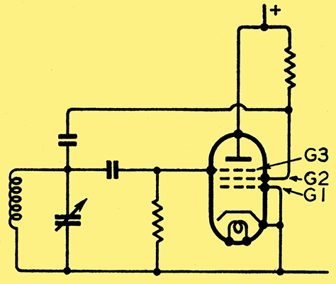
Fig. 3. Basic connections of the Herold oscillator.
This is basically the Herold oscillator. If the tuned circuit is omitted from a Franklin oscillator, the necessary phase relationship for oscillation is still present, and oscillation continues with a complicated wave form and a frequency largely determined by the resistance-capacity constants of the inter-valve couplings. This is the multivibrator [2] Multivibrator Action, E Hughes, Wireless World, Nov. 1942. (Fig. 4 (a)).
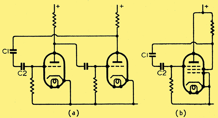
Fig. 4. Without the tuned circuit both the Franklin circuit (a) and Herold circuit (b) will continue to oscillate and can be used for frequency division.
In practice, C1 and C2 are replaced by a single capacitor of somewhat larger value than is used for the Franklin oscillator. Under certain conditions this arrangement can be made to divide frequencies. [3] Frequency Measurements, Amateur Radio Handbook, 2nd Ed., p. 219. If the tuned circuit is removed from a Herold oscillator, oscillations will continue at a frequency determined by the resistance-capacity constant of the coupling (Fig. 4 Again C1 and C2 can be replaced by a single capacitor. A similar arrangement has been used as an oscilloscope time base, [4] A Single-valve Time Base Circuit, B C Fleming-Williams, Wireless Engineer, April 1940, p. 161. but the implication that it could also be used as a frequency divider has not hitherto been explored as far as the author is aware.
Operation of an Untuned Herold Oscillator
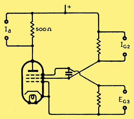
Fig. 5. Circuit of untuned Herold oscillator showing points at which oscillographic records of current and voltage were taken.
A valve was set up in the circuit shown in Fig. 5, an oscillograph being placed in turn at the points indicated.The resulting waveforms are shown in Fig. 6 (not to scale).
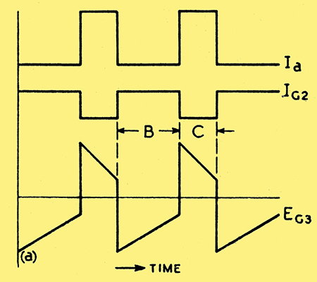
Fig. 6. Waveforms of anode current, screen current and suppressor grid voltage in the circuit of Fig. 5.
The theory of operation developed to fit in with these findings is as follows:-
Starting from point (a) on the EG3 curve, the operating point is assumed to be far to the left of Fig. 1, that is EG3 is considerably negative. This charge slowly leaks away through the grid leak until the bend in the curve is reached. During this period there is no change in IG2, and consequently no change in EG2 or Ia. As the charge falls the potential of G3 passes the bend and the G2 potential starts to rise rapidly; this in turn pulls G3 positive with it, occasioning a further sharp fall in IG2, a rise in EG2, and an increase in Ia, the operating point swinging abruptly far to the right of Fig. 1 (EG3 positive). EG3 is held positive by the condenser charge; this leaks away more rapidly than when the grid was negative because, in addition to the current flow through the grid leak, there is also an electron current to the grid. Until this charge has fallen to the bend in the positive region no change occurs in the anode or screen current; when the bend is reached there is an increase in screen current, a fall in screen potential, and G3 is driven negative again. It is clear that the ratio of the periods B to C (Fig. 6) can never be 1:1 because of the grid current when G3 is positive; the lower the value of the grid leak (which means a larger capacitor for the same frequency) the more nearly equal these periods will be. The effect of the triode grid, when a triode-hexode is used, is to increase very considerably the grid current in period C and shorten the duration to approximately 1/50th of period B.
Methods of Synchronising

Fig. 7. Method of injecting synchronising signal for frequency division. Cs = C/10 (approx).
Two possible points for injecting the synchronising signal are apparent, either at G1 or G3. Although G1 is suggested in the time base application mentioned [4] A Single-valve Time Base Circuit, B C Fleming-Williams, Wireless Engineer, April 1940, p. 161. it was not found possible to rely on this method for frequency divisions of a higher order than about 3:1. Injection on G3 through a small capacitor was more successful in practice (Fig. 7). A positive pulse will initiate the swing positive of G3 potential or a negative pulse will initiate the swing negative of the G3. When, as is usual for divider service, the synchronising source is a sine wave, then both the positive and negative swings may be used, providing the ratio B to C in Fig. 6 is suitably adjusted. Fig. 8. shows the case for division by four when the ratio B to C is 5:3.
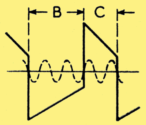
Fig. 8. Frequency division by four with B:C = 5:3.
Output Coupling
The output of a Franklin oscillator or a multivibrator can be taken from grid or anode of either triode. The coupling must be fairly loose, however, and a buffer valve is usually necessary to prevent variation in the output circuit constants from upsetting the oscillation frequency or waveform. A multivibrator functioning as a divider thus requires three valves per dividing stage. An Untuned Herold oscillator could be coupled from either G3 or G2, but since G3 is already in use for the synchronising signal, G2 is, in fact, the only available electrode. The usual buffer stage is, of course, necessary. If a valve of the frequency-changer type with separated screens was available, the buffer could be eliminated. Considering the hexode section only of a normal triode-hexode, G1 would be returned to cathode and not used, G2 would function as the G2 in the pentode case, G3 as the pentode suppressor, G4 as the pentode anode which is at earth potential with respect to the signal, and the anode as the output electrode. G4 would act as an electrostatic screen and the output would be isolated in the same manner as a Dow oscillator (Fig. 9). The number of valves per dividing stage would then be reduced to one.
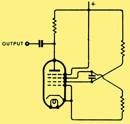
Fig. 9. In a hexode oscillator with separate screens the output could be taken from the anode without a buffer stage.
Performance of Apparatus
A three-valve, crystal-controlled frequency sub-standard has been constructed using the single-valve divider circuit. The first valve is a 1 MHz - 100 kHZ dual crystal oscillator, the second valve is a 5:1 divider which may be switched into the 100 kHz circuit, and the last valve is a harmonic amplifier.
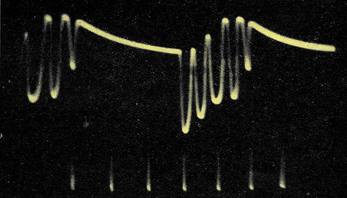
Fig. 10. Oscillograph of output from a three-stage frequency divider.
The oscillograph (Fig. 10) shows the output of the amplifier with the divider switched in and out. With the divider out the oscilloscope screen was covered with a piece of black paper so that only the tips of the 100 kHz waves are visible. The extra waves (appearing between the 100 kHz wave tips) in the divided waveform are due to amplification by the divider and the harmonic amplifier; of a strong second harmonic generated by the crystal oscillator; 20 kHz harmonics are detectable up to 15 MHz with the amplifier anode circuit untuned, and well beyond 30 MHz when the amplifier anode circuit is tuned.
References
- Negative Resistance and Devices for Obtaining It, E W Herold, Proc. IRE, Oct. 1935.
- Multivibrator Action, E Hughes, Wireless World, Nov. 1942.
- Frequency Measurements, Amateur Radio Handbook, 2nd Ed., p. 219.
- A Single-valve Time Base Circuit, B C Fleming-Williams, Wireless Engineer, April 1940, p. 161.
The references 2 and 3 are not the original publication of the relevant data, but are good recent expositions of the subjects.
|