|
Some valuable details for valve-set users are contained in this article on the choice and use of modern receiving valves.
What valve shall I use? is a question which is always cropping up among radio set owners. Every time a new set is bought, an old one is altered, or a new valve is placed on the market, the question of which valve is best for any particular job has to be answered.
And it is a question which is not easily answered for oneself, because there are so many valves available which are excellent in design and performance, there are so many duplicate models, and so many 'border-line' cases where one valve or one type can fill the bill for another valve, while the results can still be really excellent.
A Vast Number
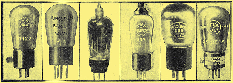
Reading from left to right, we have the 2-volt Mullard 'Pentone' PM22, the Tungsram Barium valve e.g. H210, the Mazda SG215, Mullard S4V valve, Triotron detector UD2, and the Six-Sixty 2-volt pentode (= Mullard PM22).
There are between 300 and 400 valves on the British market, so that it is indeed a difficult job for the average man to decide this problem of which is the best valve. He obviously cannot afford to go and buy several which seem to be suitable, using the best and discarding the others, so he must, make up his mind beforehand Which he will use, buy it, and stick to it. There is no chance of a trial and error method of choice of valves for others than wealthy experimenters or those closely connected with the radio trade.
Luckily the valves on the British market are pretty standard in their performances, and the majority of the valves can be chosen from their catalogue characteristics and relied upon as certain to suit any particular position.
Thus, if you have a set using one HF of the screened grid type, a detector, and two transformer-coupled LF stages, you can write to any of the big valve firms and they will tell you exactly what combination will give the best results, for any of the well-known firms is capable of supplying you for practically any contingency.
The HF Side
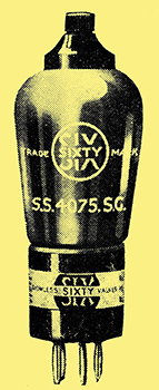
A 4-Volt Six-Sixty SG valve.
If you want a high-frequency valve, all you have to do is to ask for a high-frequency valve that is suitable for your particular set, and you will get the right valve. Moreover, if anything goes wrong with it any of the well-known makes will see that you are looked after, and if the fault is due to the construction of the valve will readily replace it.
If you want a screened grid valve, you only have to ask for a screened grid valve, and you are bound to get one that is OK. There is no trouble in HF or screened grid valves.
Where a little doubt may appear is on the LF side of the set. We will suppose for a moment that you are sure about the HF side, and that you are a bit worried about the detector and LF's.
Is there any particular golden rule which you may follow in order to make sure that you are going to get the best out of the receiver? Unfortunately there is no golden rule, but it should not be difficult to choose valves that will give you good reception, and perfectly satisfactory results with-long life.
Special Detector Types
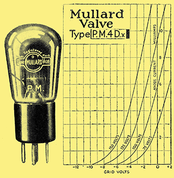
Messrs. Mullard are noted for their special detector valves, of which the 4 Volter PM4DX is shown here.
In the detector stage, whether this be transformer or resistance-coupled to the next stage, you can very rarely do better than to use one of the special detector valves such as those made by Mullards, the PM2DX, the PM4DX, the PM5X and PM6D, or else an ordinary good HF valve such as made by Marconi, Osram, Tungsram, Cossor, Mazda, Lissen, PR, Dario, Vatea, etc.
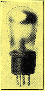
One of the PR valves.
An HF valve having an impedance of anything from 15,000 to 25,000 Ohms is suitable in this stage, while its magnification factor should, of course, be reasonably high , In other words, you will probably find it has a magnification of anything from 15 to 30.
We are dealing in this article with battery valves only, the mains valves are dealt with in another article under the title of 'Mains Drive Valves', so for the battery man there should be absolutely no trouble in finding the right detector.
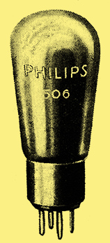
One of the many Philips rectifiers.
What about the low-frequency side? This is a little more difficult because there are one or two facts about the circuit which we must have a look at before we can finally decide which valves to use.
In the first stage we have to consider how much input in the way of signal voltage the valve will have to deal with. Then we have to consider the coupling between the valves, and we also have to consider how much anode current the valve will take.
In the first place, it is obvious that a valve on the LF side must be of such a size as to be able to deal reasonably Well with the signal impulses without wanting excessive volume controlling when the set is tuned in to the local station. It must handle enough to provide you with sufficient output volume.
Obviously the strength passed on to this valve will depend upon the detector and any HF which precedes it. If you have no HF then the matter is simplified, but if you are using one or two HF stages on the local station you are likely to get overloading somewhere in the set unless you are very careful in controlling volume, and also in the choice of your valves.
As a general rule, the first LF valve can usually be of what is known as the 'ordinary' LF type, which has an impedance of anything from 7,000 or 8,000 Ohms to 16,000 Ohms, and an amplification factor of anything from 10 to 15.
This is where we come up against some of this 'border-line' business, for we find here that the special detector valves are often quite useful in first LF stages, and you can often use one here. The ordinary HF and detector valve, however, should not be used in the first LF stage unless you are listening to a very distant station and you want all the amplification out of the set you can possibly get. For local station work the ordinary HF valve will be very badly overloaded if it is used in the first LF stage.
Now with regard to this stage, there is a point to watch about the impedance of the valve itself, especially as this determines the amount of anode current it will take at a given HT voltage.
Too Much Current.
Most modern transformers will stand up to three or four milliamps with ease, but if you increase this to, say, five or six milliamps, as you might easily do if you use too big an LF valve (one of about 6,000 Ohms or less resistance), then you will either cause saturation of the transformer core with consequent distortion of your results, or else you will very seriously reduce the inductance of the transformer primary, and by that means very badly affect the quality of reproduction.
So do not use too big a valve in this stage unless you are out for very big signals, and are working on the local station and requiring tremendous volume for your output. And in such a case shunt feed the HT through a resistance, taking the transformer coupling through a large fixed condenser.
The Last Stage
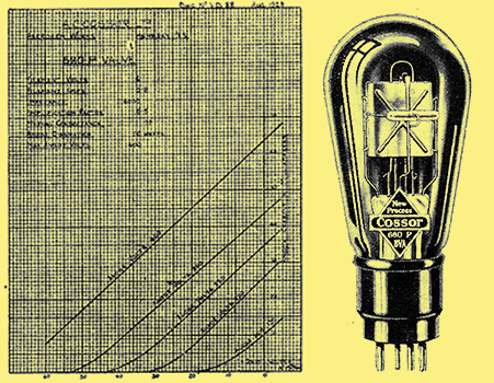
Here are the characteristic curves of a Cossor 6-volt output valve, while on the right is an illustration of the valve itself. Click the image for a PDF of the characteristics.
The last valve in a set is rather more difficult to choose than the previous one, as you have to consider the signal voltage that is likely to be impressed upon it, and you have to avoid overloading. For instance, suppose you are listening to Brookmans Park only ten or twelve miles away, and you are using a detector and two LF stages, transformer-coupled.
Suppose also you use an ordinary HF valve in the detector, and an ordinary LF, say 10,000 Ohms or 7,000 Ohms, with a high magnification factor of about 12 to 15 in the second stage. What are you going to use in the last?
Economy of HT would suggest that you use a small power valve which by the appearance of its figures shows that it gives quite a high amplification. You could take a valve of 4,000 Ohms and find quite easily that it has a. mag. of 6 or 7, and this apparently would give you tremendous signals from your speaker. But in practice you will soon find that the power valve has no hope of dealing With the input voltage applied to its grid, and will be over-loading almost continually.
Consequently you would have to detune or volume-control till you cut down strength of reproduction by a very considerable amount. In fact, you would find that you would have to cut down the strength so much that you would be actually getting less strength from your loud speaker than you could get by using a large super-power valve of the 2,000 Ohm type with a smaller magnification factor in the last stage. You always have to balance up this magnification of the valve with its grid-voltage-carrying power, for obviously you cannot get more than a certain amount out of the valve, the maximum being when the valve is fully loaded.
Super-Power Best
If the valve will not carry much load, then you will not get more than a certain comparatively small amount, and in this case that certain amount is likely to be very much less than the maximum amount you will get out of a super-power valve which will not magnify your input so much, but will allow you to put more in.
Consequently, if you are to deal with very loud signals, if you are within, say, 15 miles of a powerful station, and you are using three- or four- valve set, I would strongly recommend you to use a super-power in the last stage. You must, however, be prepared to supply it with sufficient HT current and voltage.
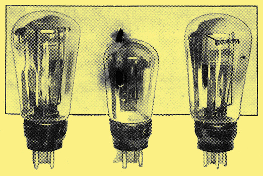
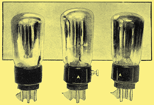
Three from the large Mazda range of battery valves. The P625B, P220, and the P650, a large super-power valve. The Mazda people have also a large range of AC mains valves.
Small Supers
A valve of the P240 class should do very well in cases where a fair volume is required, or, where slightly less volume is needed, the P2 should be very suitable. Other valves of this type, such as the PM252, Cossor 220P, Mazda P220, etc., are also available.
This latter type has an impedance of 3,700 Ohms and a magnification factor of 12.5, so that you have to be careful how much you give it so as not to overload it. It has a grid swing of something of the order of 6 Volts either side of the bias point.
The largest valves are to be found in the 4- or 6-Volt series as a rule, so that if you can use these valves you will find it better if you want really big volume. Two-Volters, however, are satisfactory for ordinary room strength and general household purposes, and it is only when you want to drive a moving coil speaker at fair volume that you have to use the 4- or 6-Volt type in order to get super-power valves capable of dealing with the volume and power required. In such cases, of course, anode voltages of something like 300 or more are also necessary; rather outside the scope of the ordinary set.
You will see, therefore, how very necessary it is to watch that output valve carefully, and in view of the fact that a super-power, or even a power valve, usually takes quite a fair amount of anode current, it is usually advisable to employ a filter output unit to keep the anode current away from the loud speaker windings, and along any extension leads which may be used to the speaker.
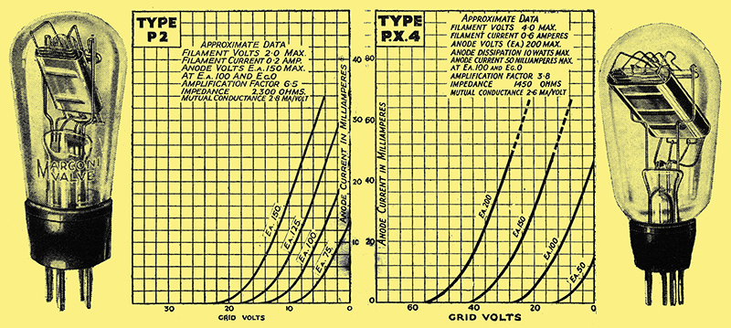
The latest Marconi and Osram super-power valves. On the left we have the P2, a remarkable 2-Volter, and on the right the PX4, a. 4-volt 'super' with excellent characteristics.
For Heavy Work
Incidentally, an output filter often makes a useful anti-motor boating device, but we cannot go into the advantages of that here, as this is purely a valve article.
For really heavy work there are some truly remarkable 6-Volt super-power valves, there is the LS6A, which has a grid bias maximum of 93 Volts and an anode current in the neighbourhood of 63 milliamps at 400 Volts.
It nevertheless has a high magnification factor for a valve of that size, something of the order of 30, while the impedance is 1,300 Ohms. This, of course, is too big a valve for the average set, though those who work moving coil speakers and run their sets from the mains will find it a useful valve.
At max. Volts HT it dissipates something like 25 Watts and takes a filament current of 1.6 amp. at 6 Volts. It is, then, as you see, a remarkably 'hefty' output valve.
RC Valves and Pentodes

The Dario Pentodian.
You will notice I have not mentioned the resistance type of valve, because I am of the opinion that this has rather a limited appeal, and it is only in cases where particularly high magnification is required in resistance stages that these valves are really useful.
As a general rule the best detectors are obtained from the HF valves, and the resistance types have rather a small grid swing, so they are not exactly suitable for LF amplification stages.
We have so far not mentioned the pentode valve, which has become very popular during the last twelve months. As an output valve for giving high magnification it is, of course, impossible to beat it, for it has remarkable amplification powers, and, incidentally quite a fair grid swing.
A 2-volt pentode valve will carry a grid swing of something like 9 Volts, either side of the bias point, which is quite a comfortable amount for ordinary small set working. In larger sets it is advisable to use the 6-Volt or the 4-Volt pentode, which usually has a bigger swing, especially the Mullard PM24A and PM24B, and the Six-Sixty 24A, which are extremely useful valves.
The PM24A has an impedance of something like 63,000 Ohms and as magnification factor of 80, and these three valves are designed for power work. They will work a moving-coil loud speaker at tremendous volume.
There is no doubt we have not heard the last of the pentode yet and that further developments will shortly take place which will give us even larger pentode valves, and even greater power carrying qualities, and even now the AC pentodes are making an appearance.
For Portable Sets
Were portable sets are concerned it is very necessary to keep the anode consumption down as far as possible, and here the special Lissen PT225 pentode, valve proves useful, because it has a low anode current consumption, only about seven milliamps, and an amplification factor of something like 90.
The impedance is 24,000 Ohms, and it is especially designed for the output of two or three valve sets such as portable receivers using HT batteries. It has not quite such a big grid swing as some of the larger pentodes, but the magnification powers make it extremely suitable for portables and small sets. In sets such as the 'Magic Two' it is very useful.
For those who want a larger pentode there is the super-power pentode - the PT240 with an impedance of only 22,000 Ohms and an amplification factor of 45. It has, of course, a larger grid swing than the PT225.
Multiple Valves
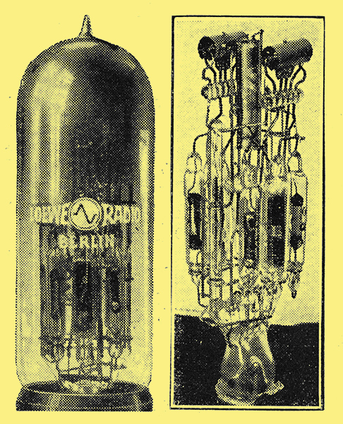
The Loewe 3NF (det. and 2 LF) valve. and the interior of the same valve showing the arrangement of electrodes, resistances, and capacities. See also 2HF
Where portable sets are concerned also we must not forget the Loewe multiple valve, in which two HF stages (resistance, of course) can be obtained, or a detector and two LF can also be supplied complete in one valve. In this case we have the three stages all in one, which is a very compact way of building up a set.
So much depends upon the valve that it should never be chosen haphazardly, for it is quite possible to ruin the whole operation of the set by choosing a poor valve in any one of its positions.
In all sets designed by wireless journals particulars are given as to the valves to use, and I would strongly recommend readers to keep to that advice. You may say, 'Oh, I have got a such-and-such valve, which ought to do quite well', whereas that such-and-such valve may be quite useless, either because its impedance and magnification factor are wrong or else because it takes too much HT current or it will not carry the grid swing required, either of which short-comings is capable of ruining the performance of the set.
A very good deal of the distortion experienced in wireless reception is due to the valves being wrongly chosen, and if you have not a volume control it becomes doubly important that you should choose your valves carefully. If. you have the slightest doubt as to the right valve to use, do write either to Popular Wireless or to the valve maker whose valve you intend to employ, and ask for advice, giving full details of your circuit and the distance from your nearest station.
The valves must carry the input from the local station satisfactorily and then they will obviously be able to deal with distant stations properly.
You may not get such magnification of that distant station as you get with a valve of higher magnification, but it is worth while sacrificing a small amount of magnification in order to get the best results from the local.
If you are out for distant reception only then you can use a valve simply for its magnification powers. If, however, you are out for quality reception, as the majority of people are, and distance afterwards, then it is advisable that you choose a valve especially carefully, and if in any doubt at all, write to PW or to the valve manufacturer for advice.
Some of-the Lissen 'twos', the HL210, Pentode (PT225), and the L210.
|