|
Practical Voltage Amplifiers
Previously we saw that we could determine the performance of an audio frequency voltage amplifier triode under working conditions by drawing a load-line across its IaVa curves. The 'slope' of the load-line corresponded to the resistance of the anode load and we noted, further, that a complete picture of the valves operation was given by adding a second load-line having a slope equal to the resistance of the anode load and the following grid resistor in parallel. This second load-line was the dynamic load-line.
We shall next turn our attention to some generally available triodes and examine their capabilities in practical circuits.
Triode Combinations
When we come to examine practical triodes intended for use as audio voltage amplifiers and for similar functions we encounter the somewhat surprising fact that such triodes are not, these days (mid 1960's), normally manufactured as single units. We find, for instance, that some valves consist of a triode voltage amplifier in combination with one or more diodes, all of these being contained within a single envelope. These particular valves are known as single-diode-triodes or double-diode-triodes, as applicable. Again, a triode may be contained in a single envelope with a second triode of similar characteristics, giving a combination which is described as a double-triode. Another common valve is the triode-pentode, in which a voltage amplifying triode is combined with a pentode. The function of the latter is, typically, that of providing sufficient power to drive a loudspeaker. (See later in the series).
The scarcity of single voltage amplifier triodes is due to developments and improvements in valve design. At present, it is possible to manufacture voltage amplifier triodes which occupy relatively little space, whereupon it becomes economically desirable to combine these with other valves in single envelopes. No conventional domestic equipment employs a single triode on its own without any other valves, and the present-day designer chooses from the currently available range of double-triodes, diode-triodes and triode-pentodes, etc., to find a combination which best meets his particular requirements. If the equipment being designed is, for instance, a radio receiver which requires only one triode voltage amplifier amongst its complement of valves, the designer may choose a suitable type combined with one or more diodes (which can be used for signal detection) or combined with a pentode (which may be used to drive the loudspeaker). If the equipment is a tape recorder, which requires a large amount of audio frequency amplification in its circuits, then double-triodes, consisting of two voltage amplifiers in one envelope, may be pressed into service. Despite the apparent anomaly that voltage amplifier triodes are not normally manufactured as single units at the time being, the combinations in which they appear can be readily incorporated in conventional equipment designs.
This situation did not hold true in the earlier days of radio, when valve development had not reached its present level, and it was quite common practice to use single triode voltage amplifier valves. Noteworthy among the earlier types is the valve type 6J5 also available in a large glass envelope as 6J5G and the small glass tubular envelope as 6J5GT, this consisting of a single indirectly heated triode fitted to an octal base. This valve still appears in current manufacturers lists as a 'maintenance type'. Since it is mounted on an IO octal base it is much more bulky than a triode of similar performance in a modern valve combination. Additionally it is also made as a double triode on the IO base and the Type designation is 6SN7GT. Triodes of the 6J5 type are still used in audio equipment in the 21st century.
All valves are given type numbers and, where necessary, a brief explanation of each type number will be given as it appears in these articles. The 6J5 type number just mentioned employs the American coding system, in which the first character is a number defining the filament or heater voltage.
The 6 in 6J5 refers to a rated heater voltage lying between 5.6 and 6.6 Volts. In practice, the rated heater voltage for the 6J5 is 6.3, this being a heater voltage which is very frequently encountered in valves intended for use in mains-driven equipment and was originally chosen as 6.3 Volts is the discharge voltage of three lead-acid accumulator's. Vehicles of the 1930's (the date when this heater voltage was introduced in America) used 6 Volt batteries. All other commonly encountered valves using the American code whose type number commences with the figure 6 also have heaters rated at 6.3 Volts. The first number is followed in the American coding system by a letter, or letters, which are allocated in sequence to new valves as they are introduced to the market. The letter (or letters) has no significance to the user, apart from the obvious one of identification.
A minor exception which applies to octal valves is that, if there are two letters and the first is S, the valve is a single-ended near-equivalent of a double-ended type having the same type number without the S. Thus, the 6SK7 (an RF amplifying pentode) is a single-ended near-equivalent of the double-ended 6K7. A single-ended valve, in this context, is one having all connections brought out to the pins at the bottom, whilst a double-ended valve is one which has one connection brought out to a metal top-cap at the top of the valve in addition to those brought out to the pins.
A second number follows the letter (or letters) and this is intended to define the number of 'useful electrodes' which are brought out to the external circuit. With the 6J5, the 5 applies to the heater, the cathode, the grid, the anode, and an outside screen which is fitted in some versions of the valve. It should be added that, apart from giving a useful indication of heater or filament voltage, the American valve coding system does not provide a great deal of information about the valve concerned.
We have stated that present-day triodes are normally combined with another valve or valves in a single envelope. It is possible to find currently produced triodes which are not so combined, but these are intended for use in special applications and not as audio voltage amplifiers.
ECC82 and ECC83
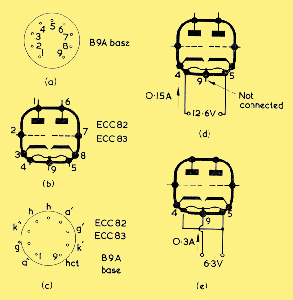
(a) The B9A base has nine pins, numbered in clockwise order with the pins pointing towards the observer
(b) illustrating the pins to which the electrodes of the ECC82 and ECC83 connect. These double-triodes are also manufactured under the type numbers 12AU7 and 12AX7 respectively
(c) An alternative method of showing pin connections for the ECC82 and ECC83
(d). The ECC82 and ECC83 may be heated from a 12.6 Volt supply by connecting to the heater in the manner shown here
(e) Alternatively, the two halves of the heater may be connected in parallel and run from a 6.3 Volt supply
The two most commonly encountered double-triodes which may be employed as voltage amplifiers in present-day equipment are the ECC82 and ECC83. These valves comprise two similar triodes in the one envelope, and they are of the all-glass construction in which the valve pins protrude directly from the glass. Both the ECC82 and ECC83 have the B9A base. The B9A base has 9 pins, these being numbered in a clockwise direction, as shown (a) above, with the pins pointing towards the observer. The greater spacing between pins 1 and 9 prevents the valve being inserted in its holder in any position other than the correct one.
Both the ECC82 and ECC83 have the same pin connections to the electrodes and these are illustrated in (b). (c) shows an alternative method of indicating the electrodes to which each pin connects. In this diagram, letter k stands for cathode. Since these valves have two triodes in the one envelope, the electrodes of one triode have to be distinguished from the electrodes of the other when showing a pin connection diagram such as that of (c). In this diagram a prime is added after the electrode letters for one triode and two primes after the electrodes of the other. In (c) we encounter the abbreviation 'hct', which stands for 'heater centre-tap'. The provision of a heater centre-tap is an unusual feature in valves intended for operation in mains-driven equipment and it considerably increases the versatility of the two valves under discussion. Either valve may be heated by connecting a 12.6 Volt supply to pins 4 and 5 with no connection to pin 9, as in (d), or by connecting a 6.3 Volt supply to pin 9 and pins 4 and 5 joined together, as in (e). When connected for 12.6 Volt operation, the heater current is 0.15 Amp and, when connected for 6.3 Volt operation, it is 0.3 Amp. The ECC82 and ECC83 may, in consequence, be operated from a 6.3 or 12.6 Volt supply, as required. Heaters in radio equipment are frequently connected in series instead of in parallel, whereupon it becomes necessary for all the heaters to be rated at the same current. The ECC82 and ECC83 may be fitted in a chain of heaters whose rated current is either 0.15 Amp or 0.3 Amp by making the appropriate connections to the heater pins.
The type numbers ECC82 and ECC83 follow European coding practice. In this, the first letter defines heater voltage or current, with E standing for 6.3 Volts (the alternative 12.6 Volt method of heater connection being ignored). The letter or letters which follow indicate the general class of valve, with letter C representing a triode. As there are two triodes, there are two Cs in the type number. The following figure indicates the type of base, with figure 8 representing B9A. The final figure, or figures, indicates a design or development number and has no significance, apart from identification, for the user.
The ECC82 and ECC83 are also manufactured under the American code numbers 12AU7 and 12AX7 respectively. In these the initial 12 indicates a rated heater voltage of approximately 12.6 (which is actually 12.6 with these two valves) whilst the final 7 indicates that seven useful electrodes are brought out to external connections (these electrodes consisting of one heater, two cathodes, two grids and two anodes). It will be noted that the American coding ignores the 6.3 Volt heater application.
As we saw in the previous article, the performance of a voltage amplifier may be found by drawing a load-line across its IaVa curves, and it will be of interest if we now carry out this process with, firstly, the ECC82 and, then, the ECC83. The IaVa curves for a single triode of the ECC82 are shown in (a) below.
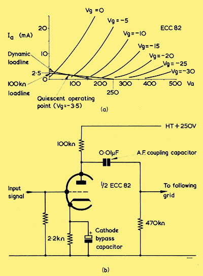
(a) Adding a 100kΩ load-line for 250 Volts HT, and a subsequent dynamic load-line, to the IaVa curves of a single triode of the ECC82. The quiescent operating point is chosen at -3.5 Volts for Vg (as judged between the Vg = 0 and Vg = -5 curves). IaVa curves for the ECC82 are usually issued with 5 Volt spacing between Vg parameters, which makes results obtained from the load-line construction approximate only. (The curves shown here and in the next illustration under (a) are presented for purposes of illustration and may contain slight inaccuracies. Readers wishing to work with the curves for the valves concerned should use those issued by the valve manufacturers - See the data-sheets embedded into the exhibits)
(b) One triode of an ECC82 connected in a circuit which corresponds to the dynamic load-line of (a) The heater is omitted for simplicity. The AF coupling capacitor has the typical value of 0.01 μF
We may undertake the exercise for an HT voltage having the typical figure of 250. A representative anode load resistor would be 100kΩ whereupon, following the procedure we saw in last months article, we can draw a load-line from the 250 Volt point on the Va axis to the 2.5 mA point on the Ia axis. We choose 2.5 mA because this is the current which would flow through the load for zero anode voltage.
The load-line is included in (a), and visual inspection indicates that the spacing between the points where the curves cross the load-line appear to be more equal to the left of the -5 Volt curve. It would be reasonable, in consequence, to arbitrarily pick a quiescent operating point at -3.5 Volts, as has been done in the diagram. Our choice of quiescent operating point results in a quiescent anode voltage having the rather low figure of 80, which is slightly below the range of 0.4 to 0.8 of the HT supply voltage which was mentioned before. The low anode voltage figure is not undesirable, however, if the choice of quiescent operating point ensures that the anode signal is not too distorted a copy of the signal applied to the grid.
If the valve is used in a conventional circuit we have to take the following grid resistor into account, and this could have a typical value of 470kΩ. 100kΩ and 470kΩ in parallel give a resistance of 82kΩ, and the dynamic load-line, with a slope equal to this resistance, is then drawn through the quiescent operating point. The results given by this load-line appear to be reasonably acceptable by visual inspection. Since our quiescent operating point is at -3.5 volts, the positive excursion of the input signal cannot exceed this figure without the onset of positive grid current. At the same time, a negative grid excursion of as much as 8 Volts approximately can take place before the valve is cut off. The valve could, therefore, handle an input signal of slightly less than 3.5 volts peak without introducing an excessively high level of distortion. Lower distortion should be offered at reduced input signal levels.
As we have stated, the quiescent operating point is at -3.5 Volts and this corresponds to an anode current of approximately 1.6 mA, as read from the diagram. If we are using cathode bias, this anode current will then flow through the bias resistor. Since we require a bias of 3.5 Volts (to bring the valve to the quiescent operating point) the value of the bias resistor (from R = E/I) is 2.2kΩ.
To check voltage gain we may examine the anode voltage change corresponding to a change in grid voltage from -5 to zero. The change in anode voltage is approximately 75 Volts, whereupon the voltage gain, under working conditions, is 75/5 or 15.
(b) shows one of the ECC82 triodes in a working circuit, this incorporating component values which correspond to the dynamic load-line of (a).
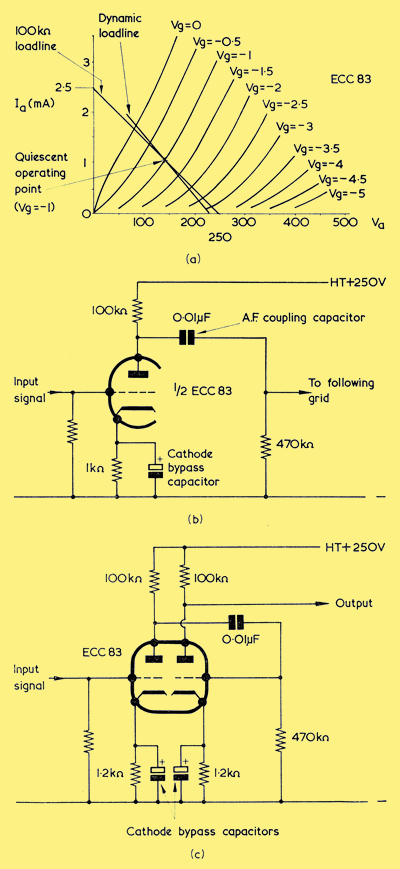
(a) The load-line construction for one triode of an ECC83
(b) The ECC83 triode in a working circuit corresponding to the dynamic load-line drawn in (a)
(c) If the two triodes of the ECC83 are connected in cascade, as shown here, the overall voltage gain is 2,500 times
In (a) above we repeat the process, using the IaVa curves of one of the triodes of an ECC83. An anode load resistor of 100kΩ would, again, be a representative value, and we draw the load-line for an HT voltage of 250. A quiescent operating point at -1 Volt appears reasonable, after which we draw a dynamic load-line with a slope of 82kΩ, to take into account a following grid resistor of 470kΩ. As may be seen, input signals up to a peak value of 1 Volt are handled without excessive distortion. The quiescent operating point corresponds to 1.1 mA anode current, and so the cathode bias resistor needs to be 900Ω. A value of 1kΩ would be adequate in practice, and the valve, with component values, is shown in (b). An examination of (a) shows that, along the dynamic load-line, a change in grid voltage of 1 (from Vg = -0.5 to -1.5) brings about a corresponding change in anode voltage of 50. Thus, the voltage gain of the ECC83 triode is 50, a significantly higher figure than that for the ECC82. If we were to connect the two triodes of the ECC83 in cascade, as we do in (c), the total gain will be 50 x 50, or 2,500. The two triodes of the ECC82, similarly connected, would give an overall gain of 15 x 15, or 225.
By comparing the ECC82 and ECC83 triodes we have found that the ECC83 triode offers greater gain in a working circuit than does the ECC82. From the IaVa curves it may be seen also that the ECC82 cuts off at a considerably greater negative grid voltage than does the ECC83, and this latter factor can be of advantage in some applications.
In (b) in the previous diagram and (b) and (c) in the current diagram, the cathode bias resistors are bypassed by electrolytic capacitors. As we saw before, a cathode bypass capacitor needs to have a low reactance at the frequencies being handled if cathode degeneration is not to occur. A suitable practical value for the capacitor in the diagrams just mentioned would be 25μF, which corresponds to a reactance of approximately 120Ω at 50 Hz. In all the circuits, the voltage dropped across the bias resistor is relatively quite low, and in each case the capacitor could be a component having a rating of, say, 6 Volts working.
DAC32
It will be helpful, next, to briefly examine a battery voltage amplifier triode, and see what differences exist between this and a triode intended for mains-driven equipment. However, voltage amplifier triodes for operation from batteries in domestic equipment have not been in general use for a number of years, and it is necessary to select rather an early valve if this class of triode is to be represented.
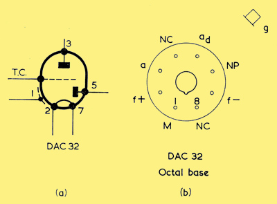
(a) Circuit symbol for the DAC32, a battery operated triode voltage amplifier combined with a diode
(b) The DAC32 is mounted on an octal base, and has the pin connections shown here
(a) and (b) show the symbol and pin connections for a typical example, this being the DAC32. As will be seen, the DAC32 consists of a diode-triode, and it is fitted to an octal base. The circuit symbol for the DAC32 is given in (a), the letters TC in this diagram indicating that the grid connection is made via a metal top cap. (b) shows the octal base, with pins numbered 1 to 8 in a clockwise direction, and with pins 1 and 8 on either side of the locating key of the centre spigot. The letters f stand for filament, whilst a(d) denotes the diode anode. The letters NC mean that no connection is made to the pin concerned, and NP indicates that no pin is fitted to the base at the point designated. The letter M stands for external metallising on the glass envelope, which provides a screen for the valve.
The filament supply required by the DAC32 is 1.4 Volts at 50 mA. In practice, the filament is designed to run from a dry cell whose voltage is nominally 1.5, but which will, during the useful life of the cell, average at around 1.4. Valves in this category draw a small anode current and are intended to operate from HT voltages of the order of 90 only. A typical anode load value would be of the order of 250kΩ, resulting in a voltage gain of around 30.
It should be noted that the filament pins for the valve are designated positive and negative in (b), and that the filament supply should be applied with the polarity indicated. The grid resistor may be connected to the negative filament pin. Ignoring the effect of contact potential, the result of this connection is that the negative end of the filament has the same potential as the grid whilst the positive end is 1.4 Volts positive of the grid, with the consequence that an effective average grid bias of about -0.7 Volt appears at the grid relative to filament. The diode anode is mounted at the negative end of the filament.
In the coding, DAC32, the letter D indicates that filament voltage lies in the range 0.5 to 1.5, whilst the A indicates a single diode and the C indicates a triode. The following number, 3, applies to an IO octal base. An equivalent valve with American coding is the 1H5, the figure 1 applying to a filament voltage in the range of 1.6 or less, and the figure 5 applying to 5 useful electrodes (filament, grid, anode, diode anode and, in some versions of the valve, screen).
In the next article we shall consider a final factor which affects triode performance, this being Miller Effect.
|