|
The New Version: Design Data: Modifications: Further Notes
August 1949
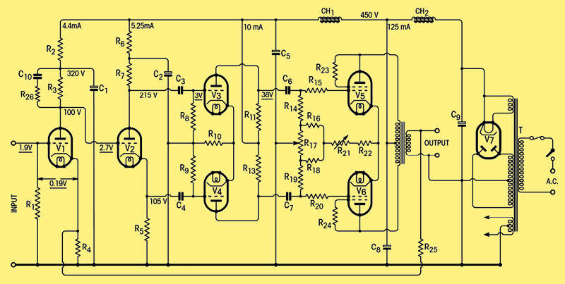
Fig. 1. Circuit diagram of complete amplifier. Voltages underlined are peak signal voltages at 15 watts output.
Since the publication in the April and May, 1947, issues of Wireless World of an amplifier design suitable for high-quality reproduction of sound, correspondence has revealed that a more complete explanation of some of the features of the design, with the addition of some information about construction, would be of interest. The correspondence also shows that considerable demand exists for a pre-amplifier unit to enable the amplifier to be used in conjunction with gramophone pickups and microphones of low output. In the present article it is proposed to deal with the amplifier, and in subsequent articles to present the design of auxiliary equipment to form a domestic sound-reproducing installation.
Circuit Diagram. The list of component values are printed again. These differ in minor detail from the originals. In the circuit previously printed a potentiometer, R12, was provided in the penultimate stage to enable the signal to be balanced. Due to the use of common un-bypassed cathode resistors for the push-pull stages, the amplifier is largely self-balancing to signal, and it is permissible to dispense with this adjustment. Accordingly, revised values and tolerances are shown for resistors R5, R7 R11 and R13.
A transitional phase-shift network consisting of R26 and C10, which was previously recommended as a temporary measure, has been added as a permanent feature to increase the margin of stability at high frequencies. This will be discussed later when the stability of the amplifier is considered.
Finally, an indirectly heated rectifier has been substituted as this prevents a damaging voltage surge when the amplifier is switched on. No suitable type was available when the circuit was originally published. A list of alternative valve types is also shown.
Amplitude and Phase/frequency Response.
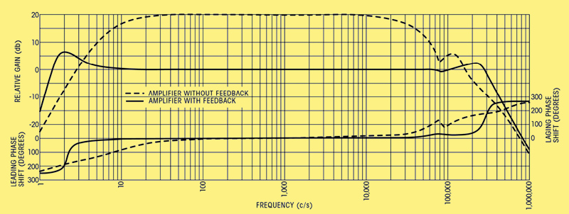
Fig. 2. Loop gain and phase-shift characteristics of the amplifier.
A curve showing the transmission and loop gain of the amplifier at frequencies between 1 Hz and 1 MHz is shown in Fig. 2. Although only the section between 10 Hz and 20,000 kHz is useful for sound reproduction, the curves outside this range are included as they may be of interest to those who may wish to use the amplifier for other purposes. They may also serve to emphasize that, in a feedback amplifier, the response must be carefully controlled at frequencies very remote from the useful range if stability is to be achieved.
General Constructional Data.
The layout of the amplifier is not critical, provided that a few simple precautions are observed. Many different arrangements have been used satisfactorily to suit differing circumstances. An excellent plan is to construct the power supply and the amplifier on separate chassis, as this gives greater flexibility in accommodating the equipment in a cabinet.
The following precautions should be observed:-
- The output transformer core should be positioned at right angles to the cores of the mains transformer and the main smoothing choke.
- The output transformer and loudspeaker leads should be kept at a reasonable distance from the input leads, which should be screened. As the response curve shows, the amplifier has considerable gain at low radio frequencies, and care is necessary to avoid oscillation.
- Signal wires, especially grid leads, should be kept as short as possible, and the stopper resistors associated with the output stage must be mounted on the valve-holder tags, and not on group panels.
- A bus-bar earth return formed by a piece of 12 or 14 SWG tinned copper wire, connected to the chassis at the input end, is greatly to be preferred to the use of the chassis as an earth return.
- Electrolytic and paper capacitors should be kept away from sources of heat, such as the output and rectifier valves.
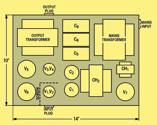
Fig. 3. Suggested layout of principal components of combined amplifier and power pack.
Figs. 3 and 4 show the positions of the major components in two alternative layouts which have been used successfully.
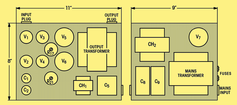
Fig. 4. Layout when using separate power pack.
Initial Adjustments.
Before the amplifier is put into service there are a few adjustments which require to be made. These concern the balancing of the standing currents in the output stage, and (with the original circuit ) balancing of the signal currents in the push-pull stages.
Accurate balance of the stand- ing currents in the output stage is essential, as the low-frequency characteristics of the output transformer deteriorate rapidly with DC magnetization. The procedure to be adopted for static and signal balancing is as follows:-
Static Balancing.
- Connect a suitable milli-ammeter in the lead to the centre tap of the output transformer primary.
- Set the total current to 125 mA by means of R21.
- Connect a moving-coil voltmeter (0-10 V approx.) across the whole of the output transformer primary and adjust R17, until the reading is zero, indicating balance. Random fluctuations of this instrument may be noticed. These are due to mains and valve fluctuations and should be disregarded.
Signal Balancing.
- Connect the low-impedance winding of a small output transformer in the lead to the centre tap of the output transformer. Connect a detector (headphones or a cathode-ray oscillograph if available) to the other winding, earthing one side for safety.
- Connect a resistive load in place of the loudspeaker.
- Apply a signal at a frequency of about 400 Hz to the amplifier input to give an output voltage about half maximum.
- Adjust R12 for minimum output in the detector.
The Output Transformer.
As stated previously, the output transformer is the most critical component in the amplifier and satisfactory performance will not be obtained with a component differing substantially from the specification. The effect of decreasing the primary inductance will be to produce instability at low frequencies, which can be cured only by altering the time constants of the other coupling circuits, or by decreasing the amount of feedback. At high frequencies the situation is more complex, as there are more variables. The leakage inductance, the self-capacitance of the windings, the capacitance between windings and the distribution of these parameters determine the transmission of the component at high frequencies, and great variations are possible.
In the output transformer specified, the only parameter which is likely to vary appreciably is the inductance of the primary at low signal levels, due to the use of core material with a low initial permeability, or to careless assembly of the core. The high-frequency characteristics are not dependent on the core material to a substantial degree. They are dependent only on the geometry of construction, and to some extent upon the dielectric properties of the insulants used, and are therefore reproducible with a high degree of accuracy.
Comments are frequently expressed about the size of the output transformer. It is true that it is considerably larger than the transformers which are usually fitted to 15 Watt amplifiers. The fact that the peak flux density of 7,250 Gauss for maximum output at 20 Hz lies on the upper safe limit for low distortion is sufficient comment on current practice.
Some confusion arose regarding the method of connection of the transformer secondary windings to match loads of various impedances, whilst utilizing all the secondary sections. The correct primary load impedance is 10,0000 and as the turns ratio in the original design is 76 : 1 the impedance of each secondary section is 10,000 Ω/762 or 1.7 Ω. When secondary sections are connected in parallel, the turns ratio, and hence the impedance ratio, remains unchanged. If now two secondary sections, or sets of paralleled sections, are connected in series the turns ratio is halved, and the secondary impedance, being proportional to the square of the turns ratio, becomes 1.7 x 22 = 6.8 Ω. Similarly if three sections are connected in series the impedance becomes 1.7 x 32 = 15.3 Ω. Thus the available secondary impedances, keeping a 10,0000 primary load impedance, are 1.7, 6.8, 15.3, 27, 42.5, 61, 83 and 109 Ω. The connections to obtain these values are shown in the table.
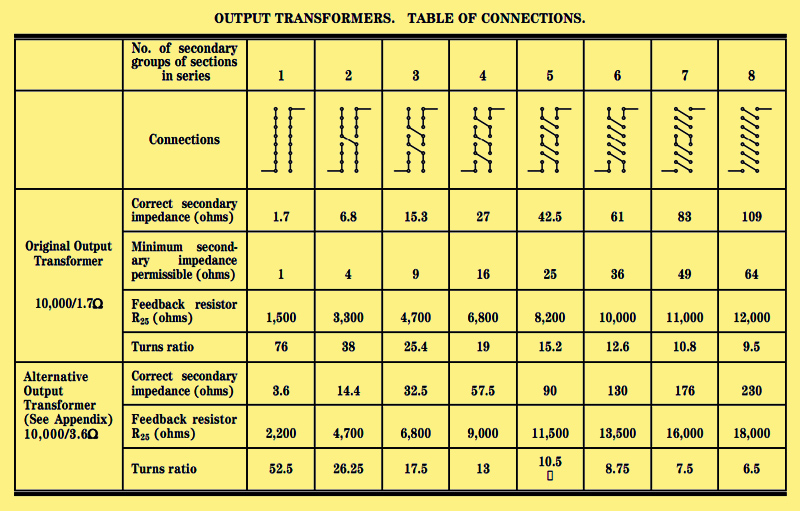
Should it be necessary, in an emergency, to match loads of other impedances to the amplifier, it is permissible to reduce the primary load impedance to 6,000 Ω giving another series of secondary impedances, namely 1, 4, 9, 16, 25, 36, 49 and 64 Ω. Under these conditions the power output will be increased slightly and the distortion will be doubled. The value of the feedback resistor R25 must remain unaltered, as the turns ratio is unchanged. The values of R25 are given in the table.
Winding data for an output transformer to match loads in the region of 3.5 Ω are given in the Appendix and the connections and other data are included in the lower section of the table. The two outer layers of the output transformer primary should normally be connected together to form the centre tap, the inner sections of the winding being taken to the valve anodes. This gives the minimum external electric held.
Stability with Negative Feedback.
Much has been written about the stability of amplifiers under conditions of negative feedback, and the criteria for stability are now widely appreciated. The article by 'Cathode Ray' in the May, 1949, issue, states the matter simply and with characteristic clarity. Continuous oscillation will occur in a feedback amplifier if the loop gain (that is the transmission of the amplifier and the feedback network) is greater than unity at any point where the phase shift of the amplifier has reached 1800. It is also possible for an amplifier to be unstable in the absence of continuous oscillation if these conditions should occur in a transient manner at a critical signal level. This latter condition is particularly likely to occur in badly designed amplifiers with iron-cored components, where the inductance and, therefore, the time constant controlling the phase and amplitude characteristics of one or more stages may increase by as much as a factor of five between zero and maximum signal levels. If this variable time constant is shorter than those of the fixed coupling circuits, an increase in its value due to a high signal level may be sufficient to render the system unstable. In order to avoid this condition the fixed time constants must be made much longer than that of the variable stage. This condition would lead to undesirably large interstage couplings if good low-frequency response were required. Alternatively, the variable time constant must be chosen in relation to the fixed time constants, such that its minimum value is sufficiently longer than the fixed values to produce stability. An increase in its value then serves only to increase the stability margin. This method is used in the amplifier under discussion.
To ensure a wide margin of stability, whilst at the same time preserving the high loop gain necessary to reduce the effect of transformer distortion at frequencies of the order of 10-20 Hz, would require a transformer with a very large initial primary inductance. This would necessarily be expensive, and a compromise must be drawn between the three factors. Because of this, the margin of stability must be kept to the lowest practicable value.
When the amplifier is reproduced, the 'spread' in tolerance of components will normally be such that changes in characteristics due to departure from the nominal value of one component will be balanced by opposite changes produced by departure in another component, and the amplifier as a whole is likely to have characteristics close to the average. Individual amplifiers may, however, have characteristics which differ substantially from the average, due to an upward or downward trend in the changes produced by component deviations. If the trend is in a direction such that the loop gain is reduced, no instability will result, the only effect being a slight degrading of the performance. If, on the other hand, the loop gain is increased by an amount greater than the margin of stability, oscillation will occur. It should be emphasized that this will happen only very rarely, and when it does the remedy is obviously to reduce the loop gain to its correct value.
To assist the unfortunate few who experience instability, the following procedure is recommended. If oscillation should occur at a low frequency (about 2 Hz) the first step should be to disconnect the feedback resistor R25. If the oscillation continues the de-coupling circuits should be checked and any faulty components replaced. The amplifier should also be examined to ensure that it is operating correctly balanced in push-pull, and not in an unbalanced manner due to the failure of some component.
Primary Inductance
Assuming that the amplifier is, or has been rendered, stable with the feedback disconnected, the next step should be to check the phase and amplitude characteristics at low frequencies. It is not practicable to make direct measurements of these characteristics without very special equipment, as inspection of Fig. 2 will show that the interesting region lies below 10 Hz. It is therefore necessary to arrive at the desired result by indirect means, namely by measurement of the component parameters which determine the characteristics. The parameter which is most likely to show a large deviation from specification is the initial primary inductance of the output transformer, since the quality of the core material is not easy to control accurately, and careless assembly of the core may cause considerable variations in its permeability.
The initial primary inductance should be checked by connecting the primary winding across the 5.0 V, 50 Hz rectifier heater winding of the mains transformer and measuring the current in it. The secondary windings should be on open circuit. The current, which can just be read on the 10 mA AC range of a Model 7 Avometer, should be 150 μA or lower. The component should be rejected if the current exceeds 200 μA.
If the output transformer is satisfactory the values of the other components should be checked, particular attention being paid to the coupling components. Should the time constants of the couplings, that is their RC product, be higher than the nominal values by more than 20%, the resistors should be adjusted to give the correct value.
The trouble will probably have revealed itself by this time, but, if upon re-connecting R25 the oscillation is still present, it is very likely to be due to the use of valves with mutual conductances higher than average, and it is legitimate to increase the value of R25 to reduce the loop gain. If instruments are available, the loop gain may be measured by disconnecting R25 from the cathode of V1 and re-connecting it via a 470 Ω ± 10% resistor to chassis. The voltage gain, measured from the input grid to the junction of R25 and the 470 Ω resistor, should be 10 at frequencies between 30 Hz and 10 kHz. Care must be taken not to overload the amplifier when this measurement is being made.
The adjustment of the loop gain to its correct value at medium frequencies should render the amplifier stable at high frequencies. It is unlikely that the phase characteristic at high frequencies of individual amplifiers will deviate appreciably from normal unless the layout is very poor or the transformer is not to specification.
Capacitive Loads
The amplifier is absolutely stable at high frequencies with a resistive or inductive load, but it is possible for oscillation to occur when the load impedance is capacitive at very high frequencies, for example, when a long cable is used to connect the amplifier and loudspeaker. To avoid this possibility, and to give an increased margin of stability, a transitional phase-shift network consisting of R26 and C10 in conjunction with the output resistance of V1, has been included in the circuit. This has the effect of reducing the loop gain at frequencies from 20 kHz upwards without affecting the phase shift in the critical region.
The use of a phase advance network consisting of a capacitor shunting R25 has been advocated as a means of stabilizing this amplifier. The effect of such a network is to increase the loop gain at high frequencies, at the same time reducing the amount of phase lag. It is sometimes possible by this means to steer the phase curve away from the 1800 point as the loop gain is passing through unity, thus increasing the margin of stability.
The connection of a capacitor across R25, however, will not stabilize this amplifier if it has been constructed to specification, although it may produce improvement if oscillation is due to some large departure from specification, such as the use of an output transformer with completely different high-frequency characteristics. The writer has no information about this.
The use of separate RC bias impedances for the output valves has also been suggested. This procedure is not endorsed by the writer, as there are numerous disadvantages in its use and no redeeming features whatsoever. If the time constant of the bias network is made sufficiently long to ensure that the low-frequency performance of the amplifier is unimpaired, the phase shift of the bias network will have its maximum at or near the lower critical frequency and may provoke oscillation. If, on the other hand, it is made sufficiently short to avoid this, the ability of the amplifier to handle low frequencies will be impaired. The use of separate bias impedances destroys the self-balancing properties of the amplifier, and if two dissimilar valves are used in the output stage 'motor boating' is likely, due to the presence of signal in the HT line. The performance of the output transformer may be seriously affected by the out-of-balance current caused by valves whose anode currents lie within the manufacturer's tolerance limits. Finally, there can be little justification of this modification on economic grounds, as the costs are roughly similar. Indeed, if the question of replacement due to failure is considered, the common bias arrangement shows a definite saving.
It is to be hoped that these remarks on stability will not have the effect of frightening those who already possess amplifiers of this type or are contemplating acquiring them. Their purpose is to help the occasional 'outer limit' case where instability is experienced, but if they serve to impress upon the reader that negative feedback amplifiers are designed as an integral unit, and that any modifications, however insignificant they may appear, may seriously affect the performance or stability, a useful purpose will have been accomplished. Such modifications should be attempted only by those who are confident that they know what they are doing, and who have access to measuring equipment to verify results .
Appendix
Output Transformer with 3.6-ohm secondaries
Winding Data
Core: 1.75 inch stack of 28A Super Silcor laminations. (Magnetic and Electrical Alloys, Burnbank, Hamilton, Lanarks.). The winding consists of two identical interleaved coils each 1.5 inch wide on paxolin formers 1.25 x 1.75 inch inside dimensions. On each former is wound 5 primary sections, each consisting of 440 turns (5 layers, 88 turns per layer) of 30 SWG enamelled copper wire interleaved with 2 mil. paper, alternating with 4 secondary sections, each consisting of 84 turns (2 layers, 42 turns per layer) of 22 SWG enamelled copper wire interleaved with 2 mil. paper.
Each section is insulated from its neighbours by 3 layers of 5 mil. Empire tape. All connections are brought out on one side of the winding, but the primary sections may be connected in series when winding, two primary connections only per bobbin being brought out. Windings to be assembled on core with one bobbin reversed, and with insulating cheeks and a centre spacer.
Components
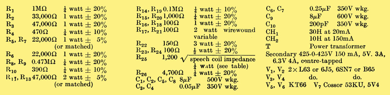
|