|
Driver/Phase Splitter Circuits
The function of a phase splitter circuit is to the. now amplified. signal –which is of course single phase in nature – and derive from it two equal amplitude, anti-phase signals, balanced about ground. These signals are used to drive the control grids of the push-pull output valves in opposition. Phase splitting, of one type or another, is always necessary with valves. since there is no equivalent of the complementary NPN/PNP devices found in semiconductors. Driving the grid of a valve in a positive direction causes an increase in anode current, whereas driving the grid in the negative direction causes a decrease in anode current. This fact dictates the need for a pair of anti-phase inputs.
One way of splitting the phases is to use an input transformer to the output stage with the secondary centre-tapped. this point being grounded. Indeed this technique has been extensively used in the past, but it carries with it all of the attendant disadvantages of such devices, not least of which is the possible poor performance at high frequencies due to shunt capacities. The trend was, therefore. to move away from the use of transformers in favour of circuits employing other techniques, some of which are described below.
The Concertina Phase Splitter
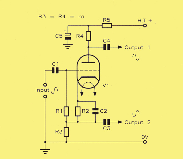
The concertina phase splitter.
The diagram shows what some may consider to be the classical phase splitter circuit, the concertina phase splitter. This rather colourful title is derived from the way in which the voltages at the output points of the circuit emulate movements of the hands of the musician in playing a concertina. Thus. with this mental picture, it isn't too difficult to visualise the outputs rising and falling in phase opposition.
To achieve this, use is made of the fact that there is a phase shift of 0° between the control grid and the cathode, and a phase shift of 180° between the control grid and the anode. Thus these two electrodes automatically provide the two anti-phase signals required, and all that is then necessary to do is to design the circuit so that these two voltages are equal in amplitude. To achieve this, the resistors R3 and R4. which are the cathode and anode loads respectively, are made of equal value and also equal to the ra of the valve. The voltage gain of the stage is then slightly less than unity, usually about 0.9. To balance this obvious disadvantage. the outputs can be balanced to within less than 1%, although it is necessary to use close tolerance resistors for the loads. No initial adjustment for balance is then necessary. The circuit is also simple and requires only one valve. The grid bias for the valve is derived from the resistor R2 in the cathode lead, in the usual way, the grid leak Rl being returned to the lower end of R2 rather than to ground.
The Paraphase Splitter
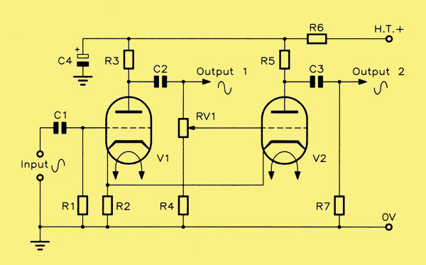
The paraphase splitter.
An alternative circuit is the paraphase splitter. This uses a pair of triodes and, as expected. would usually employ both parts of a double-triode valve. In operation. this can be regarded as a two-stage amplifier in which each of the stages contributes one of the two complementary outputs. The input to the second stage is derived from the output of the first stage, this being tapped off using the potentiometer RV1. In this way the two outputs can be made identical, but it requires some initial setting up, observing the two outputs on a double beam or dual trace CRO (Cathode Ray Oscilloscope) while RV1 is adjusted. However, this twin valve phase splitter version has the advantage of higher gain and greater output over the concertina type, but appears to have rather poor response at high frequencies, arising because of the necessarily low value of resistor R4.
Improved Paraphase Splitter
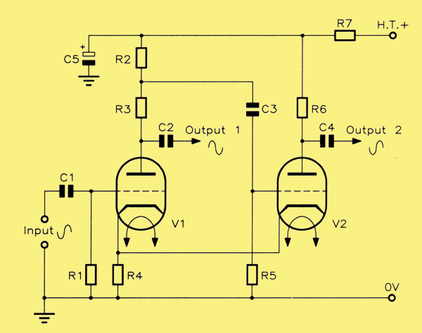
An improved paraphase splitter.
A version of the above described paraphase splitter, with greatly improved HF response, is now presented. In this circuit, the principle remains essentially the same, but the potentiometer action is obtained by splitting the anode load of the first stage into two resistors, R2 and R3. These are proportioned so as to provide just sufficient drive to the second valve so that its output equals that of the first stage. Because the grid leak resistor V2 (R5) can now be made larger, the HF response is better.
The Cathode-Coupled Phase Splitter
See also High-quality Audio Amplification.
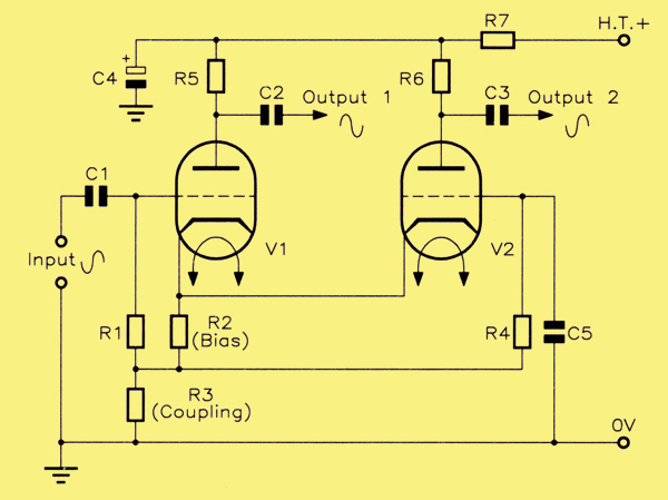
Cathode coupled phase splitter.
The name of this circuit derives from the fact that the only signal coupling between the two stages is provided by their common cathode resistor R3. The way in which the circuit works is as follows:–
If the grid of V1 is driven in a positive direction, the anode current of V1 increases, which causes an increase in the voltage across the coupling resistor R3. At the same time the anode voltage of V1 is falling. The increased voltage drop across R3 means that the cathode of V2 is now more positive relative to its grid than it was before (but only because C5 is AC coupling the grid of V2 to ground as a reference). It is as if the grid had been driven negatively, the result being that the anode current of V2 falls. The anode voltage of V2 then rises. From this we can see that the signal drive to the grid of V1 alone produces a pair of anti-phase voltages at the two anodes. Furthermore, these two voltages are equal in amplitude.
For AC signals, the grid of V2 is connected to ground via the capacitor C5. The size of this capacitor is important, If it is not large enough, then there will be an imbalance at low frequencies due to the fact that the grid of V2 will not be truly grounded, but connected to a tapping point on the divider formed by R4 and C5 across R3. However, it also provides a very useful degree of immunity to unwanted very low frequencies. improving the stability of the circuit. The circuit uses a common cathode bias resistor, R2, with individual grid leaks R1 and R4. There is a slight imbalance in the outputs at all frequencies because of the current flow through the resistors R1 and R3, but this effect can be minimised if R1 is made large; values of 2 MΩ often being used. Also, because of basic inefficiencies, losses can cause the non-inverted output from V2 anode to be slightly less in amplitude than the inverted output from V1 anode. A well-worn method of compensating for this is to increase the value of R6 slightly by adding another resistor in series, whose value is 5% or less than that of R6 (as a guide). In the days when only cruder, less than accurate carbon resistors were available, it could be suggested (by Mullard in one case) to test the two anode resistors with an ohmmeter. It would be quite likely that they were different. You then fit the one having the greatest resistance as tested in the R6 position!
This imbalance of outputs, and the various methods needed to compensate for it, seems to be the main aspect about the twin-valve splitter that annoys the 'concertina' fans (in that they can't understand why anybody should insist on wanting to use it if the 'concertina' is the 'best'). Another possible disadvantage has to do with valve ageing. While each of the two triodes sharing the same envelope would, arguably, be very closely matched (coming from the same batch), their characteristics may alter slightly with age, causing imbalance. However, the main advantage of the cathode-coupled paraphase splitter is inherent voltage gain, which the 'concertina' doesn't have. This, together with a greater output voltage swing capability, can provide enough signal drive for less sensitive triode and 'ultra-linear' pentode output stages, but from only two valve envelopes. For the same type of output stage the 'concertina' usually had to be followed with an additional amplifying push-pull stage, as is the case with the Williamson designs requiring three valve envelopes.
A Combined Preamplifier and Phase Splitter Circuit
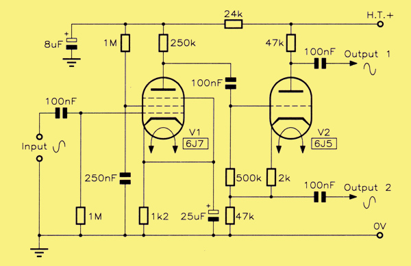
Combined preamplifier and phase splitter circuit.
The final circuit comprises a typical pentode first stage voltage amplifier followed by a triode concertina phase splitter. In the original circuit, a 6J7 pentode is followed by a 6J5 triode, both of these being on the earlier International Octal bases. All of the true gain of the circuit resides in the pentode stage of course, the phase splitter, as said earlier, actually introducing a small loss. Taking the two stages into account, the overall voltage gain is reckoned to be of the order of 84 or so, the proportion of gain and loss being 94 for the pentode and 0.9 for the triode.
For the 6J7 pentode, the parameters are μ = 1,500; ra = 1.5 MΩ. It is impossible to realise the full gain of such a valve, which can only be done if the anode load is made much greater than ra, because the HT requirement would be for an unrealistically high value of supply voltage.
This configuration became very popular in the hey-day of valve power amplifiers, and can take several forms. A preceding triode might be used in place of the pentode, for instance, in which case a double-triode would fit the bill (eg, a 6SN7 as in the 1947 Williamson amplifier). It is also possible for the grid of the second valve to be directly DC coupled to the anode of the first valve, making the two biasing resistors and coupling capacitor redundant and reducing component count, but it means that the DC level at V1 anode must be maintained at something like a third of the total supply voltage for the second stage to ensure correct biasing of V2.
Also published was a Mullard variation of this where an EF86, taking the place of V1, directly connects to the first grid of a double-triode paraphase splitter like the improved design above, using a ECC83. There is only one common cathode resistor, and DC bias for the second triode comes also from the anode of V1 , but via 1 MΩ decoupled to ground with 100 nF, A 6J5 and 6SN7 in this configuration also work well.
|