|
Contents
(Within the text click a heading to return here)
- Performance of Amplifying Equipment
- Power Reserve
- Distortion
- Harmonic Distortion
- Intermodulation Distortion
- Hum and Noise
- Cross-talk Interference
- Negative Feedback
- Circuit Design
- Output Stages
- Pentode Push-pull Stages
- Triode Push-pull Stages
- Distributed Loading
- Intermediate Stages
- Input Stages
- Noise
- Hum
- Microphony
- Starvation Operation
- Pre-amplifier Stages
Introduction
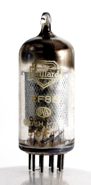 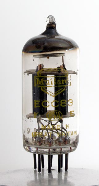 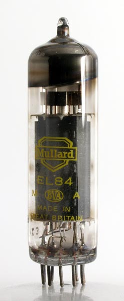 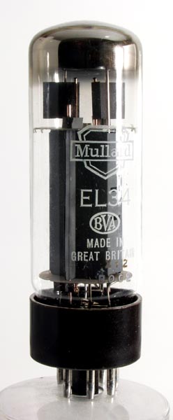
The Mullard hi-fi audio valve range from the 1950's onwards. EF86, ECC83, EL84 and EL34.
The principal features of good amplifying equipment can be summarised as follows:–
- The distortion produced by the amplifier should be negligible up to the maximum output level. Distortion is the presence in the output of frequency components which were not present in the input signal. These consist, in the first place, of harmonics of the original frequencies and, in the second, of sum and difference tones caused by intermodulation between different frequencies.
- The response of the amplifier should be uniform throughout the audible frequency range. The average ear will respond to frequencies in the range of 30 Hz to 15 kHz. The upper limit of this range may extend to 20 kHz, particularly with young people, or be well below 15 kHz with older people. The upper partials of some musical instruments extend to about 10 kHz and the sound spectrum associated with them to about the upper limit of the audible range. To make realistic reproduction possible, therefore, the amplifier should handle a range of frequencies at least as wide as that which can be heard.
- The response of the amplifier to signals of a transient nature should be good. Many sounds, particularly those deriving from musical instruments, rise very rapidly to a high intensity and decay relatively slowly. Such sounds are spoken of as 'transients', and examples of these are the sounds resulting from the clashing of cymbals or the plucking of strings.
The steeply rising wave fronts of transient sounds can be shown to consist of a wide range of component frequencies. The ability of an amplifier to reproduce these transients faithfully will therefore depend on two things: first, the frequency response of the system must be wide and, second, the phase shift over the whole frequency range must be small. Variations in the relative phasing of the component frequencies of a transient would result in a change in its aural character.
- An adequate reserve of output power should be available. For faithful reproduction, the sound level should be comparable with that of 'live' conditions. The amplifier should thus be capable of handling peak powers considerably above the average level to allow peak sounds to be reproduced without overloading and audible distortion.
- The output resistance of the amplifier should be low. This will improve the performance of the loudspeaker and ensure crisp and clean reproduction, particularly of transients. Air-loading of the loudspeaker limits, to a large extent, the low-frequency resonance of the cone and suspension. The electromagnetic damping afforded by a low output resistance in the amplifier is, however, effective in ensuring adequate control of the cone movement over the whole frequency range. The output resistance should preferably be much less than the impedance of the loudspeaker voice coil, the ratio of the two being termed the 'damping factor'. In practice, a damping factor of above 10 is desirable.
- The level of hum and noise should be low: the presence of these in the loudspeaker output will detract from the enjoyment of otherwise good reproduction. Thus the amplifier should not give rise to noise or hum at an audible level.
The performance of amplifying equipment is normally stipulated with reference to some or all of the points enumerated above, and the interpretations to be given to the values quoted in subsequent chapters of this book are discussed in the following paragraphs, In the chapters on stereophonic equipment, the performance of each channel is quoted. Combined values for the two channels can be misleading. For example, a reserve of output power (see below) of, say, 5 W per channel does not mean that an output of 10 W will be delivered before overloading occurs. Overloading will occur in the left-hand channel if that channel has to deliver more than 5 W, and similarly in the right-hand channel. For sound sources placed symmetrically between the right- and left-hand microphones, the total power reserve will be 10 W, but for sounds originating in either extreme left- or right-hand positions, the total reserve is little more than the reserve of the left- or right-hand channel.
Power Reserve
The audio power available at the output of an amplifier is defined as (V load)2/Rload, where V load is the voltage developed across a load resistance Rload connected to the output terminals of the amplifier. The rated output power, or the power reserve, of the amplifier is the maximum audio power which can be obtained without exceeding either the limiting values of the valves or the level of distortion permitted in the specification for the equipment.
Distortion
The principal form of distortion occurring in the output from amplifying equipment is non-linear distortion which is normally divided into harmonic, intermodulation and beat-note distortion. Each sub-division contributes some power to the amplifier output at frequencies which differ from those occurring in the input signal.
Harmonic Distortion
Power which occurs in the output at second, third, fourth, and so on, harmonics of the fundamental signal frequency comprises harmonic distortion. It is expressed as a percentage ratio of the power associated with the particular harmonic to the total output power of the amplifier. Total harmonic distortion is the ratio of the power associated with all the harmonics to the total output power. The total harmonic distortion Dtot is given in terms of the individual distortions D2 , D3 , D4 , etc. as:–
Dtot = √(D22+D32+D42+ ...)
Intermodulation Distortion
If an input signal contains several different frequencies, any non-linearity in the amplifier will give rise to modulated waveforms having frequencies which are the sums and differences of the interacting waveforms. The extent of this distortion is assessed by measuring the degree of interaction between two pairs of test signals. The interaction between signals of very different frequencies is quoted as intermodulation distortion and that between signals of nearly equal frequencies is given as beat-note distortion.
Intermodulation distortion is measured between test signals having frequencies of 40 Hz and 10 kHz. The ratio of the peak-to-peak amplitudes of the LF and HF signals is 4:1. The output obtained with the two signals is taken to be equivalent to the output obtained with a single sine-wave signal the peak-to-peak amplitude of which is equal to the peak-to-peak amplitude of the combined waveform. The distortion is quoted as the RMS value of the amplitudes of the sum and the difference waveforms, expressed as a percentage of the amplitude of the HF signal.
Beat-note distortion is measured with two test signals having frequencies of 14 and 15 kHz. The amplitudes of these signals are equal, and the resulting difference waveform, expressed as a percentage of the test signal amplitudes, gives the beat-note distortion. The equivalent output power of the combined waveform is defined as for intermodulation distortion.
The test frequencies given above are British Standard test frequencies. American Standard test frequencies are 70 Hz and 7 kHz for intermodulation distortion and 9 and 10 kHz for beat-note distortion. Distortion figures would be lower when referred to the American Standard test signals than when referred to the British Standard signals, but the actual distortion is obviously the same in the same amplifier. Examples of this are shown below for the 10 W amplifier.
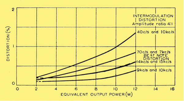
Inter-modulation and 'beat note' distortion characteristics
Hum and Noise
Contributions to the output from various stray signals picked up at points in the amplifier are normally assessed together, and are often measured as the voltage developed at the output when the input is short-circuited to earth. This voltage is expressed in decibels as a fraction of the rated output voltage measures across the load resistance, so that:–
Hum and Noise (in dB)
20(log10)[(Voltage with input shorted) / (rated output voltage)]
A level of hum and noise of, say, 60 dB, means that the rated output voltage is 1,000 times the voltage developed when the input is short-circuited to earth.
Cross-talk Interference
Cross-talk interference can arise in stereophonic equipment as a result of the signal in one channel 'breaking through' into the other. Such interference is measured as the voltage developed at the output of one channel when the input of that channel is open-circuited and the signal applied to the other channel is sufficient to give the rated output from this other channel. This voltage is expressed in decibels as a fraction of the rated output voltage obtainable from one channel.
Negative Feedback
Negative voltage feedback is used in high-quality amplifiers to improve the performance. Part of the signal is taken back and injected in an earlier stage of the amplifier in opposite phase (180° out of phase) thus reducing sensitivity. It is usual to refer to the amount of feedback in terms of the ratio of voltage gain of the amplifier without feedback to the gain with feedback. Thus feedback of, say, 26 dB would mean that the gain without feedback is 20 times the gain with feedback.
The gain of an amplifier without feedback must therefore be great enough to allow for the reduction in gain caused when the feedback is applied. This drawback is outweighed by the following advantages to be obtained from using feedback: (1) reduced distortion; (2) wider and flatter frequency response; (3) reduced output impedance; (4) reduced phase shift: (5) less dependence on small changes in supply voltages, etc.
Circuit Design
Although the power-handling capacity of an audio amplifier is not the property which is most important to the listener –a low level of distortion is usually considered to be so– it is nevertheless the prime concern of the circuit designer. The reserve of output power required for realistic reproduction of orchestral music depends mainly on the size and acoustical nature of the room and, to a lesser extent, on the taste of the listener. In the home, it is generally considered that a peak output power of 7 to 10 W will be adequate (assuming a loudspeaker efficiency of 5%) See 5-10 Amplifier. If simplicity and economy are the governing considerations, a reserve of about 3 W can, if the amplifier is carefully designed, give a generally acceptable standard of performance See 3-3 Amplifier. In large rooms or small assembly halls, however, the conditions will probably merit a maximum output power of at least 20 W See 5-20 Amplifier. The type of output stage used will depend on the maximum audio power demanded of the amplifier.
Consequently, the design of amplifying equipment will normally proceed from output to input, the requirements of the output stage dictating to' a large extent the design of preceding stages.
For output-power reserves of up to about 5 W, single-valve output stages in which the valve operates under class A conditions, are considered satisfactory. Triode valves used as power amplifiers yield a relatively distortion-free output, but their power-handling capacity is generally inadequate. The power-handling capacity of pentodes, however, is sufficient to permit their use in such stages and although the inherent distortion is high, negative feedback can be used to reduce it to an acceptable level.
There exists a choice of two basic forms of output stage from which a good-quality audio output of more than 5 W can be delivered to the voice-coil of a loud-speaker. The two well-known forms are:–
- A class AB1 push-pull pentode (or beam tetrode) output stages;
- A class A or AB push-pull triode output stage.
The choice between these is largely a balance between economy and performance.
Class A operation is that in which the values of bias and signal voltages applied to the control grid of the valve ensure that anode current always flows.
Class AB operation is that in which the values of bias and signal voltages applied to the grids of the valves cause anode current to flow in each valve for appreciably more than half, but less than a whole, cycle of the signal voltage.
Pentode Push-pull Stages
The use of pentodes of the 12 W anode-dissipation type operating in a conventional class AB push-pull stage enables an effective output of 12 to 13 W to be obtained easily assuming an output transformer efficiency of about 80% (which is a fairly conservative estimate for the efficiency). The appropriate supply voltage, limited by valve ratings, is about 300 to 320 V. The power efficiency (that is, the ratio between the audio output power and the DC input power) of such a stage is fairly high, being 50%, for example, in a typical stage using two Mullard output pentodes, type EL84. Harmonic distortion, however, is of the order of 3 to 4% at full output and, thus, a large amount of negative feedback is necessary to reduce the distortion to an acceptably low level (say 0.5 %) at maximum output.
The conditions for class AB operation normally recommended and published by valve manufacturers are based on measurements made with continuous sine-wave drive. The bias under zero-drive conditions and the anode-to-anode load resistance are so chosen that the optimum performance is achieved when the working points of the valves are displaced under driven conditions. This displacement is caused by the effect of increased anode and screen-grid currents on the cathode-bias circuit. For a typical output stage working from a 3l0V HT supply and using EL84 valves, the rise in cathode current –and thus in cathode bias voltage– with a sinusoidal signal voltage is about 40% at full drive.
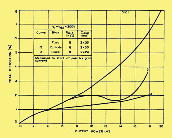
Variations of distortion with output power for two EL84 in class AB push-pull
When such a stage is used in the reproduction of speech or music, however, the operating conditions are different. The mean amplitude of the input signal is now very small compared with the peak values which occur from time to time, and thus the mean variation in cathode current is also very small. Because of the relatively long time constant of the bias network, even under peak signal conditions, the displacement of the working point is small enough for the stage to be considered as working with fixed bias. When a nominal, cathode-biased, class AB stage is examined under the corresponding fixed-bias conditions with a sine-wave input, it is found that, at high output levels, distortion is greater than when cathode bias is used. These two conditions are shown for two EL84 by Curves 1 and 2 above. The quiescent bias is the same in both cases, Curve 2 showing normal operation with cathode biasing and Curve 1 showing operation with fixed bias. The results indicate that, in practice, a cathode-biased class AB stage designed on the basis of a sinusoidal drive will produce increased distortion when peak passages of speech or music are being reproduced.
One practical method of improving performance is to adjust the quiescent operating conditions in the output stage so that they are nearly optimum for fixed-bias working, although cathode bias is still being used. This entails a smaller standing current Ia(o) and a lower anode-to-anode load impedance Ra-a. These changes result in larger variations in the instantaneous anode and screen-grid currents when the stage is driven, but the effect of these is lessened because the time constant of the cathode-bias network has also been increased. The excursion of the working bias is still kept very small under driven conditions.
It is found that good short-term regulation of the HT voltage is ensured by the use of large (50 μF) electrolytic capacitors for the anode and screen-grid supplies. Peak currents corresponding to near-overload conditions are effectively provided by the capacitors with a reduction in the line voltage of well under 0.5 %, and the instantaneous power-handling capacity of the stage is not impaired
This modified design is described more fully in The Mullard 5-10 Amplifier as an alternative 'low-loading' version of the amplifier, and it has proved to be a very satisfactory arrangement. A secondary feature of the use of these operating conditions is that the 12 W output valves each run at a mean dissipation of only 7.5 W. The corresponding fixed bias conditions in this case are represented by Curve 3 in the above diagram.
The low-loading form of operation is, however, suitable only for use in the reproduction of speech or music and cannot be used with sine-wave input without excessive distortion resulting. For this reason it is difficult to measure directly the distortion levels which hold under practical conditions.
A second method of improving the performance of pentode push-pull output stages is the use of 'distributed-load' conditions. This is discussed in detail later. Depending on the precise loading used, the variation in anode and screen-grid currents can be reduced to such a level that almost identical performance is obtained with cathode and fixed bias.
Triode Push-pull Stages
The level of distortion is inherently low in a triode push-pull output stage in which the valves operate more or less under class A conditions. It is found that if 25 W pentodes (or beam tetrodes) are connected as triodes, an output power of 12 to 15 W with a level of harmonic distortion below 1% can be obtained using a supply voltage of 430 to 450 V.
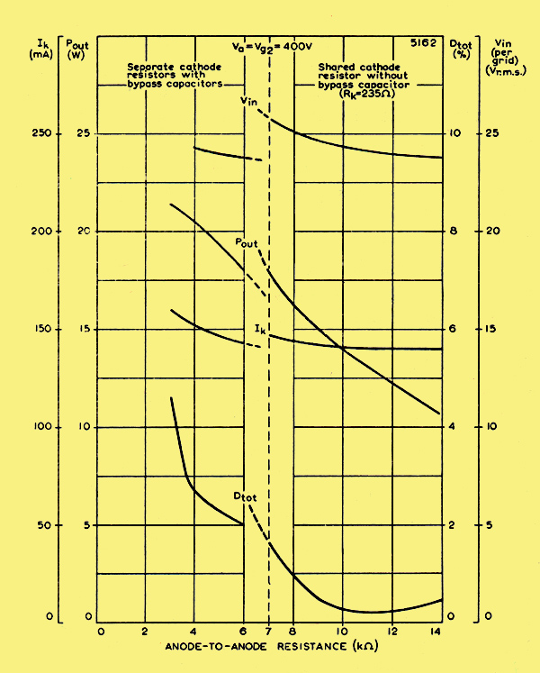
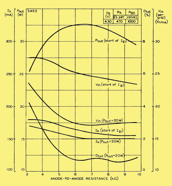
Performance characteristics of two EL34 in triode connected push-pull arrangement.
Maximum output power and the corresponding distortion vary appreciably with the value of load impedance. The curves of the above diagram illustrate the performance of two Mullard high-slope output pentodes, type EL34, connected as triodes in a push-pull output stage, operating slightly below their anode-dissipation rating of 25 W. For anode-to-anode load impedances below 7 kΩ, either a shared, bypassed cathode resistor or separate bypassed cathode resistors can be used. Above 7 kΩ however, improved operation is obtained if a shared resistor with no bypass capacitor is used. Operating conditions approach class A as the anode-to-anode impedance is raised, and the optimum performance for high-quality output stages is obtained with a load impedance of about 10 kΩ An output of l4 W is then delivered by the valves with total harmonic distortion well below 1%.
This type of output stage found favour for a number of years in high-quality amplifiers giving about l2 W effective output. Because of the low inherent distortion of these triode-connected stages, less negative feedback is required to give acceptable linearity than has to be used in pentode or beam tetrode stages giving similar output powers. Furthermore, in a three-or four-stage design in which feedback is applied over the whole amplifier, including the output transformer, it is thus possible to obtain greater margins of stability for a given level of distortion.
Distributed Loading
The conditions of distributed loading are achieved by applying negative feedback in the output stage itself. In the simplest form of distributed-load operation, the screen grids are fed from suitably positioned taps on the primary winding of the output transformer, and the stage can be considered as one in which negative feedback is applied in a non-linear manner via the screen grids.
The characteristics of the output stage under these conditions of operation lie between those for pentode and triode operation. They approach the triode characteristics as the percentage of the primary winding common to the anode and screen-grid circuits increases. Under optimum conditions, about two-thirds of the power-handling capacity of the corresponding pentode stage can be realised with a much lower level of distortion while, at power levels corresponding to triode operation, the distortion also is of the order corresponding to triode operation. At the same time, the output impedance is reduced to a level approaching that obtained if a conventional triode push-pull stage is used.
An output stage with distributed loading can thus be used with pentodes of the 25 W type in high-quality amplifiers designed for output 'powers well in excess of 15 W, the power efficiency being appreciably greater than with triode operation. Alternatively, the performance of 12 W pentodes can be improved considerably and, although the power handling capacity is reduced somewhat, effective output powers of 10 to 12 W can still be obtained.
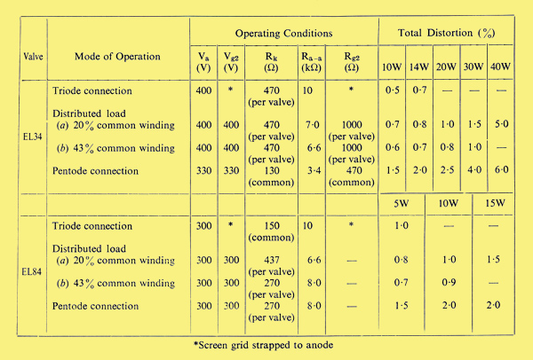
Comparison between triode, pentode and distributed load operation of EL34s and EL84s.
A comparison is given in the table above of triode, pentode and distributed-load operation for the Mullard output pentodes, types EL34 and EL84. For the EL34, the comparison between distributed-load operation and triode operation is of most interest. It will be seen from this that distributed-load operation using a tapped-primary output transformer enables the power-handling capacity to be more than double that possible with triode operation whilst, at the same time, distortion in the stage can be kept very low.
Although with a common-winding ratio of 0.2 (that is, with 20% of the primary winding common to the anode and screen-grid circuits) the distortion level is comparable with triode conditions, it has been found that appreciable improvement is obtained at higher output powers if the ratio is further increased. Progressive improvement has been obtained as the percentage of common primary winding is increased up to 40 or 45%. The power-handling capacity of the stage is reduced further as the ratio is increased, but at least 35 W can be obtained with a level of distortion at the onset of grid current of about 2.5%.
Typical performance curves of the EL34 when used with an output transformer having the primary winding tapped at 43% of the turns are shown in the diagram below. The output powers quoted are those delivered to the load in the secondary circuit.
Performance characteristics of two EL34 in pentode connected push-pull arrangement under conditions of distributed load.
With valves of the 12 W dissipation class, comparison with normal pentode operation is more significant. Appreciable reduction in odd-harmonic distortion is again obtained under distributed-load conditions, and an output of approximately 15 W is delivered by the valves if the common winding ratio is 0.2.
There are two advantages not apparent in the above table, in using a common-winding ratio of about 0.4 when a high output power is available. First, almost identical performance figures are obtained under cathode- and fixed-bias conditions since, with the closer approach to class A triode operation, variations in anode and screen-grid currents are reduced when the stage is driven. Second, as with normal triode operation, output power and distortion are less dependent on the value of load impedances: with a common-winding ratio of 0.4, little change in performance is produced by altering the anode-to-anode load from 6 to 9 kΩ However, Table I shows that there is little benefit to be achieved in respect of distortion by increasing the common-winding ratio beyond 0.2 and, because of the greater power-handling capacities possible, the circuits described in this book which use distributed loading are designed for output transformers having 20% of the primary winding common to the anode and screen-grid circuits.
To ensure stability in an amplifier when negative feedback is used to reduce distortion, the phase shift must be small. Thus, the number of stages should be a minimum. For low-output equipment such as the 3 W amplifier Mullard 3-3, it is usually possible to obtain the desired output with only a voltage amplifying input stage and a power-amplifying output stage. However, for equipment using a push-pull output stage, the penultimate stage must be capable of providing a well-balanced push-pull drive voltage of adequate amplitude. Consequently, extra stages will be required to give the push-pull drive voltage and to provide sufficient amplification of this voltage.
With push-pull stages using 25 W pentodes such as the EL34, the maximum drive voltage required is approximately 2 x 25 V RMS For stages using 12 W pentodes (the EL84, for example) the requirement is about 2 x 10 V RMS (These input-voltage requirements are similar for triode, pentode or distributed-load operation.) If a high-impedance double triode such as the Mullard ECC83 is connected as a cathode-coupled phase splitter, it is possible to produce the above drive voltages and also to perform the necessary phase splitting in a single intermediate stage.
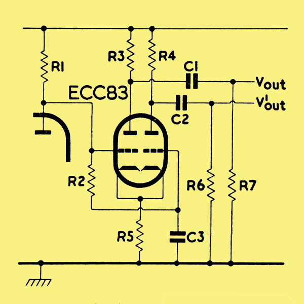
Cathode-coupled phase splitter.
A cathode-coupled phase splitter using an ECC83 is shown above. A negative pulse at the grid of the first triode section of the ECC83 produces a positive pulse at the first anode, so that Vout is positive-going. The cathodes are strapped together, and therefore go negative at the same time. The negative pulse on the second cathode is equivalent to a positive pulse on the second grid so that V¹out is negative going. Hence: V¹out is 180° out of phase with Vout. The grid of the second section of the valve is capacitively earthed by C3 for cathode input, and R2 ensures correct DC conditions in the second section.
The input grid of the circuit is directly coupled to the anode of the preceding valve so that the grid is at a direct potential of between 70 and 80 V. The bias is obtained by the voltage developed across the shared cathode resistor R5, and the direct potential of the cathode is therefore high. The cathode currents of both sections flow through R5, the DC components being additive and the AC components in opposition.
For there to be some AC signal remaining on the cathode to inject into the second section, the two sections cannot be operated with exactly equal anode loads nor with equal grid resistors in the following stages. The anode load R4 of the earthed triode section should be slightly higher than R3 to give perfect balance. Because of the high amplification factor of the ECC83 (μ is 100) exactly equal resistors cannot cause more than 3% lack of balance and nominally equal resistors, matched to within 5%, result in a lack of balance which cannot exceed 2%.
The grid resistors R6 and R7 for the output valves must be of close tolerance (±5 %) as they form part of the load to the phase splitter. The frequency at which low-frequency unbalance occurs depends on the time constant R2C3 and this can be made long enough to maintain adequate balance down to low audio frequencies. R2 will be of the order of 1 MΩ so that unbalance is caused if any leakage current flows through C3. This is a common cause of distortion.
High-frequency balance is largely determined by the layout of the wiring which can make shunt capacitances unequal. The inter-electrode capacitances of the ECC83 are sufficiently small and equal between the two sections for their shunting effect on the circuit to give negligible unbalance at high frequencies.
The effective voltage gain (Vout/Vin or V'out/Vin) is about half that of one section used as a normal voltage amplifier. Nevertheless, there is sufficient gain in this stage because of the high amplification factor of the ECC83. The absence of the input coupling capacitor reduces low-frequency phase shift, and makes for good stability when feedback is applied.
Because of the direct coupling to the preceding stage, the anode voltage of the preceding valve determines the operating conditions of the ECC83. If this anode voltage is too high, the negative bias on the phase splitter is too low, and overdrive on peak signals will result in grid-current distortion. If the anode voltage is too low, the bias of the phase splitter will be too high and the valve will operate away from the linear part of its dynamic characteristic, and distortion will be greater.
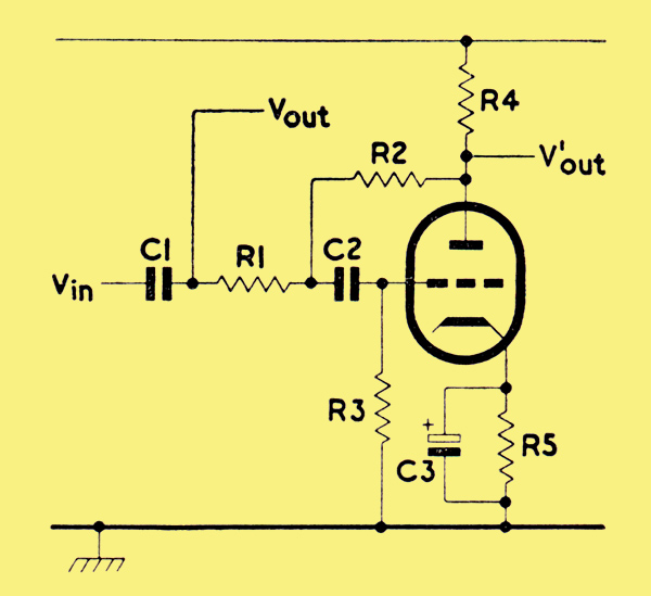
Anode-follower phase splitter.
An alternative type of phase splitter – or more correctly, phase reverser – is illustrated above. This circuit has various names such as anode follower, see-saw and paraphase.
One input for the push-pull output stage is the output Vout from the stage preceding the phase reverser, and the other is the output V'out from the phase reverser. The input for the phase reverser is taken from the potential divider R1, R2 connected between the two outputs. When Vout is positive-going, the grid is positive-going, and the anode is negative-going, so that Vout and V'out are 180° out of phase. The values of R1 and R2 are chosen so that the gain of the phase-reversing stage is unity (that is, V'out/Vin = 1). The ratio R1/R2 is equal to the ratio (A-1)/(A+1) where A is the gain of the phase-reversing valve measured from grid to anode. The circuit is less widely used than the phase splitter described above because a lack of balance between the two outputs can result from the coupling capacitors. However the circuit has two advantages:–
- It does not require a voltage difference between heater and cathode, so that it is suitable for directly-heated valves or for double-valves in which the second sections are needed for other purposes.
- If a voltage does exist between heater and cathode – as in the heater chain of a DC/AC amplifier for instance – the large amount of negative feedback from anode to grid can be used to counteract excessive hum pick-up.
Input Stages
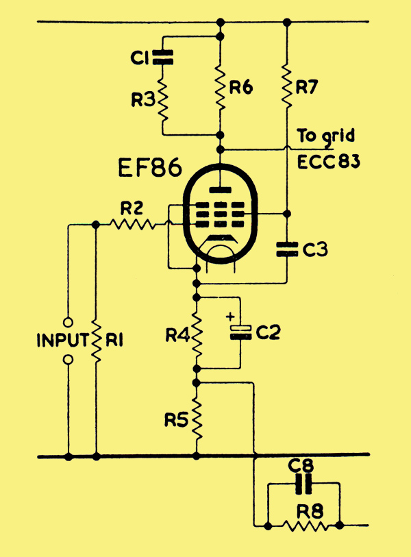
Typical EF86 input stage.
A low level of hum and noise is essential in the input stage of an amplifier because high gain is required in this stage to provide a good signal-to-noise ratio and to compensate for the reduction in gain resulting from the use of negative feedback. The recommended valve for input stages is the Mullard low-noise pentode, type EF86 (or, in DC equipment with series heater chains, type UF86 with a 100 mA heater, nominally 12.6 Volts). A conventional EF86 voltage-amplifying stage is drawn in the diagram above.
The anode load is shown shunted by a CR network which produces an advance in phase and thus increases the stability of the amplifier at high frequencies. Negative feedback (from the secondary winding of the output transformer) is introduced across a high stability resistor R5 in the cathode circuit. The feedback resistor R8 should be of the high-stability type. The feedback network C8,R8 attenuates frequencies in the ultrasonic range and again gives increased stability. The stage is intended for direct coupling to the input grid of a cathode-coupled phase splitter so that the phase shift at low frequencies is minimised and the low-frequency stability of the amplifier with feedback is improved.
The following sections describe the precautions needed to ensure that the good properties of the EF86 are realised in the typical circuit shown.
Noise
High stability, cracked-carbon resistors should be used for the anode load R6, the screen-grid resistor R7, and the cathode-circuit resistors R4 and R5. If normal carbon resistors are used, the low noise level of the EF86 may be masked by additional non-thermal noise generated by the flow of current in the resistors.
The low-frequency noise generated by the EF86 itself is most conveniently specified as an equivalent voltage at the control grid. For an HT line voltage of 250 V and an anode load of 100 kΩ, the equivalent noise voltage is 2 μV for a bandwidth of 25 Hz to 10 Hz. The bandwidth has to be specified because the random noise of the valve covers all possible frequencies, and also because the noise voltage is more or less proportional to the bandwidth. For comparison, a resistance of 100 kΩ in the grid circuit produces a thermal noise voltage of about 4 μV for the same frequency range.
Hum
The cathode resistor R4 is bypassed at signal and hum frequencies by the capacitor C2. Heater emission or the choice of an unsuitable valveholder leading to capacitive coupling or leakage between the pins, may give rise to a heater-to-cathode current. The following list indicates points which should be considered when constructing an amplifier:–
- A low-Loss valveholder must be used. A nylon-loaded phenolic holder, preferably skirted, is generally adequate.
- The external leads to the heater should be run as a twisted pair to neutralise their external magnetic fields. (The heater of the EF86 is itself made in the form of a spiral.) The heater wiring should be kept as close to the chassis as possible.
- Earth returns should be made to a busbar. Connections can be made to the central spigot of each valveholder in the first instance. The busbar should only be connected to the chassis at one point, preferably near to the input terminal. Hum picked up from currents circulating in the chassis is then kept to a minimum. Wherever possible, an external earth connection should be made.
- Where a recommended layout for the component is given, there will be no danger of hum being generated by the magnetic field of the mains transformer acting directly on the electrode supports. If some other layout is tried, the possibility of this form of hum occurring should be considered very carefully.
When used as a normal voltage amplifier with an HT line voltage of 250 V, an anode load of 100 kΩ and a grid resistor of 470 kΩ the maximum hum voltage of the EF86 itself when one side of the heater is earthed, is about 5 μV at the grid, and the average value is about 3 μV. The maximum level with a centre-tapped heater is only 1.5 μ. Additional external screening of the valve is not normally required.
Microphony
The EF86 has a rigid electrode structure. When correctly sited, the action of sound waves (acoustic feedback) and vibration on the electrode structure will not produce any audible howl. When the valve is sited in an obviously doubtful or unsuitable position as, for example, in tape recorders, a flexible mounting for the valveholder or a separate weighted sub-chassis is advisable. There are no appreciable resonances in the EF86 below 1 kHz. At higher frequencies, the effect of vibration is generally negligible because of the damping provided by the chassis and valveholder .
Starvation Operation
In a single-valve output stage, pentodes are essential if adequate output power is to be obtained. Inherent distortion with pentodes, however, is high, and a large amount of negative feedback is needed to reduce the distortion to an acceptable level. Consequently, a very high gain is essential in the input stage to compensate for this, particularly if only one stage of voltage amplification is used.
It is well known that the gain of a voltage amplifier can never reach the theoretical maximum represented by the amplification factor μ of the valve. The gain, in fact, is given by the expression μRa/(Ra + ra), where ra and Ra are the internal slope resistance of the valve and external load resistance respectively.
Practical considerations in conventional circuits restrict the extent to which the anode load can be increased. For example, the maximum will depend on the effect of shunt capacitances and the need to maintain the frequency response at the upper end of the audio spectrum. The load will normally be less than 500 kΩ and this value, used with an EF86 operating with a line voltage between 250 and 350 V, will give a stage gain of about 250. In these conditions, the anode and screen-grid voltages will be 60 and 70 V respectively.
If a more severe limitation of frequency response is acceptable, much higher values of anode load may be used. These higher values produce 'starvation' operating conditions: valve currents and voltages are much, smaller than those of conventional stages, but the stage gain is much greater. The frequency response is restricted under starvation conditions, but it can be extended considerably by the use of corrective feedback.
Because of the high value of anode load for starvation conditions, the input impedance of the following stage will need to be high. Preferably, it should not be less than 10 MΩ. Direct coupling to the grid of the following stage is possible, and the screen grid of the voltage amplifier can be fed from the cathode circuit of the following stage. Because of the low values of current and voltage and the favourable effect of these on negative grid current, starvation conditions are useful in high input-impedance voltage amplifiers.
Pre-amplification may be required with power amplifiers to provide extra voltage gain when certain kinds of input source are used. Often, it is convenient to include the treble and bass tone controls and the volume control in the pre-amplifier. Also, the preamplifier can be designed to give compensation for the bass attenuation and treble boost which have been applied by the manufacturers during recording to obtain more favourable ratios of signal to motor rumble and signal to surface noise. Pre-amplifiers for use with tape-recording equipment will also provide equalisation for the inherently non-linear nature of magnetic recording.
Pre-amplifiers for stereophonic equipment must necessarily be more complex than monaural units because a stereophonic pre-amplifier is more or less two monaural circuits in one. Furthermore, coupling must exist between corresponding controls in each section of the stereophonic circuit so that comparable adjustments can be made to both channels. If the principle of design adopted is that both channels must be identical, then rigid ganging of the controls can be used. However, if it is intended to cater for non-identical channels, concentrically-operated controls which will permit individual and coupled adjustment of the channels, will be needed. (There is strong evidence suggesting that the two channels of a stereophonic arrangement need not be identical. Excellent results are obtainable, for example, if one channel uses a 20 W power amplifier and the other, a control-less 10 W amplifier. Of course, the settings of the gain and tone controls in each channel of the pre-amplifier will need to be different because of the different characteristics of the power amplifiers.)
Even if nominally identical channels are used, the acoustical outputs from the two loudspeakers will not be exactly the same unless precautions are taken. Differences can occur because of (i) the difference in the outputs from the halves of stereophonic pick-up heads, (ii) the unequal sensitivities of the loudspeakers and (iii) the very small differences in gain of the two amplifying channels. If the volume control consists of a dual-concentric potentiometer, individual adjustment to each channel will rectify any lack of balance. If a dual-ganged potentiometer is used, a special balance control is required. It should be possible with this control to increase the gain in one channel while simultaneously decreasing it in the other. Also, it should be possible to increase and decrease the gain of one channel with respect to the other, and it is desirable that the degree of control available in either sense should be the same, so that asymmetrical, 'centre-zero' arrangement is needed.
Another facility normally required in a stereophonic pre-amplifier which is not necessary in a monaural circuit is a switch to allow the transference of the input signals from one channel to the other. Also, this switch usually serves to combine both channels, so that the equipment can be used with monaural recordings.
All pre-amplifiers, because they provide the inputs to the power amplifiers, must be designed to send as little hum and noise as possible into the main amplifier. Hum and noise in the early stages count as signal voltages and are not reduced by feedback. There is therefore no advantage in including a pre-amplifier in the feedback loop. In fact, the switching required for compensating and equalising circuits and the frequency-selective networks in a high-gain pre-amplifier are likely to produce large phase shifts and, consequently, to increase the risk of instability if included in the feedback loop.
|