|
Audio Amplifiers
We shall this attempt to join together the design aspects from earlier in the series to form practical, complete audio amplifier systems.
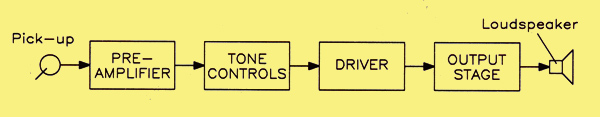
Conventional signal path for an audio amplifier.
The conventional approach to audio amplifier design results in a signal chain of the type seen above. The signal input from a transducer, such as a magnetic pick-up, tape head or radio tuner is 'conditioned' in a preamplifier. This conditioning process may involve nothing more than raising the signal level by one or two stages of wideband amplification. On the other hand, it may involve tailoring the frequency response in a particular way, such as meeting the RIAA compensation curve for magnetic pick-ups. Since the input requirements are somewhat different from other types of transducer, it is usual to provide switching for each input, so as to select the conditioning components required in each case.
Following this first preamplifier stage would be the tone controls, with at least bass and treble lift and cut controls being provided, but often a more comprehensive single 'tone' control was incorporated. (Not forgetting a volume control, of course.) Any additional facilities included special filters known as 'rumble' and 'scratch' (high-pass and low-pass) filters. One must remember that, during the period when such circuits were common, 78 rpm records were still in use, the earlier ones with inherently higher surface noise –due to the fact that they were manufactured from a mixture of shellac and a filler – and especially if they had been in use for some time. Some form of top-cut reduced the effects of surface noise. though often at the expense of high frequency signal reproduction. The surface noise of the 'new' Vinylite records. both 78 rpm and LP types. was much less. Motor rumble was also a problem with crystal pick-ups, since these were susceptible to the low frequency vibrations (in the range of 5 to 50 Hz) emanating from the turntable motor. whereas magnetic pick-ups. which produce an output proportional to velocity (and hence signal frequency) were hardly affected.
The next stage, following the volume control. would be the driver. developing enough signal to drive the output stage to its rated output. The output stage required two anti-phase signals. since it was of the push-pull type. The driver might, therefore. have to perform this function and could be referred to as a phase splitter, of which there were many different variations.
We shall look, then, in turn, at these stages up to the output stage.
The Preamplifier
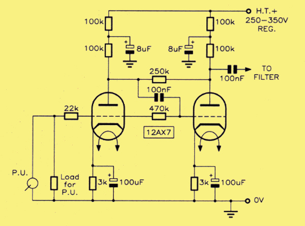
A two-stage preamplifier, from the early 1950s designed for a magnetic pick-up.
Here 'the preamplifier' is usually taken to mean one which performs amplification and RIAA equalisation for a record deck. An example of a two-stage preamplifier circuit is shown above. This is able to use either the 6SL7 or 12AX7 (ECC83) double-triodes; the former is an earlier type of valve on the larger International Octal base. Some of the values may seem a bit odd as they don't exactly match the current preferred values, but could be rounded up or down to meet current practice. It is claimed that each stage can contribute a voltage gain of between 50 and 60. giving an overall voltage gain to the output of about 3,000 times. The intended input device is a magnetic pick-up cartridge.
RIAA equalisation could take one of two forms; either passive, where the first stage has a linear frequency response and merely drives a RC correction network feeding an output stage. The set open loop gain overcomes losses in the network. Alternatively equalisation could be achieved as an inherent part of a negative feedback loop. as is now universally done with solid state circuits. In the circuit above the negative feedback loop is used.
Negative feedback between V1 anode and grid occurs through the series path comprising a 0.l μF (100 nF) capacitor and a 470 kΩresistor. (For convenience the 470 kΩ resistor is shown connected to the right-hand side of the valve's envelope; actually this is exactly the same point where the 22 kΩ resistor connects. there is only one grid pin.) Negative feedback is applied in a similar manner to the second stage, through the series path comprising the same 0.1 μF capacitor and a 250 kΩ resistor. This pre-amplifier circuit is intended to feed into the tone control circuit (below) via a 0.1 μF AC coupling (DC blocking) capacitor. The tone control provides bass and treble controls and a two-way switch to compensate for the different characteristics of 78 rpm and LP records.
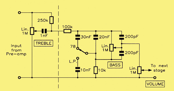
Tone control circuit for use with the 1950s preamplifier.
There were many different ways of obtaining control over tonal response in the early days of Hi-Fi reproduction. with adherents of the various methods making claims that their way was the best. Strange to think that modern design has dispensed with this 'vital' facility entirely! However. Briggs and Garner, writing in 1952 in Amplifiers. the Why and How of Good Amplification, say 'tone control circuits are a necessary evil; they cannot improve quality, but they are necessary on account of the recording characteristics ...' They are referring here to the differences between the recording characteristics of 78 rpm and LP records.
But we digress. The 22 kΩ input resistor works in conjunction with the 0.1 μF / 470 kΩ loop around V1 to provide a 'virtual earth' mode of input. in the same way as is done with modem operational amplifiers. It sets the gain of the stage. which varies over the frequency range due to the reactance of the capacitor. The value of the pick-up load resistor is chosen to trim the net input impedance to match the transducer.
The HT supply of both stages in the 1950s design at the top of the page are individually decoupled to ground, this being a vital part of the design of audio-frequency amplifiers, in order to avoid instability due to coupling between stages through the common power supply line. The true anode load of each stage is a 100 kΩresistor, wired directly in the anode lead. Above this is a low-pass filter comprising a further 100 kΩ resistor going to the positive terminal of the supply, and an 8 μF electrolytic capacitor to ground. As a result of this filtering, the alternating component of the anode current does not flow back to the supply, but is shunted to ground through the 8 μF capacitor, after first passing through the 100 kΩ anode load and developing the output voltage of the stage. (These days of course you'd be hard pressed to find an 8 μF electrolytic, but a modern –and, to be honest, better – 10 μF high voltage type will do just as well.)
Tone Controls
Tone control circuit for use with the 1950s preamplifier.
The tone control circuit above is of the 'passive' type and is formed by cascading a treble control with a bass control the division between the two sections being shown by the vertical dotted line. The output level is controlled by a 1 MΩ linear potentiometer. Taking the bass section first, this is a 'Connoisseur' circuit (Connoisseur being a well-known name from the earlier days of Hi-Fi) that gives variable bass compensation for both 78 rpm and LP records. The two 200 pF capacitors maintain constant response at high frequencies. otherwise the following capacitance of the wiring and input of the next stage could cause HF loss. In the treble section. the value of the capacitor can be anything between 0.0002 μF and 0.002 μF (200 pF and 2 nF, though apparently the value given of 0.00l μF (1 nF) offers a good compromise for both types of record.
Another Tone-controlled Preamplifier
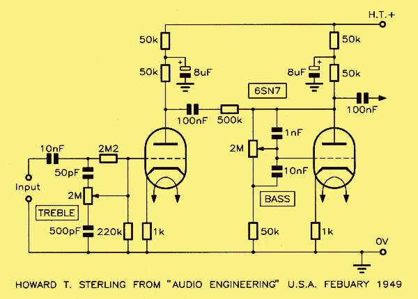
A tone-controlled preamplifier.
The circuit above uses the once popular 6SN7 (an octal based double-triode, still available from valve suppliers as 6SN7GT. 6SN7GTY. etc.). employed as a two-stage preamplifier with the treble control in the input circuit of the first stage. and the bass control between the two stages. The claimed performance of this circuit, which goes back to 1949, is 40 dB of bass control at 20 Hz and 30 dB of treble control at 10 kHz. the crossover point being at 800 Hz. The circuit is particularly useful for record reproduction because the treble cut comes in an octave higher than the top lift. so enabling surface noise to be reduced without adversely affecting the middle-to-high response and spoiling the output quality. Note again that the supplies to both stages are decoupled by their own filters comprising an 8 μF capacitor in conjunction with a 50 kΩ resistor.
It is possible to obtain tone compensation by the use of selective negative feedback. In a simple case, it is possible to make the cathode bypass capacitor smaller than the usual value, so giving incomplete bypassing at all frequencies. The effect of this is to introduce some degree of negative feedback at low frequencies (where the reactance of the bypass capacitor is high), so causing a roll off of gain in this part of the frequency spectrum. The amount of control obtained will obviously depend upon the relative values of the cathode bias resistor and its bypass capacitor.
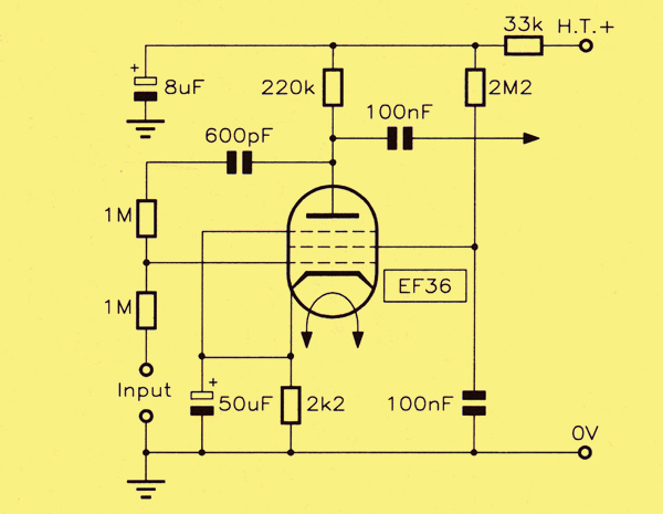
Tone (bass) control by negative feedback.
The diagram shows a method whereby negative feedback is introduced between anode and control grid of an EF36 pentode valve. The feedback path comprises a series combination of 1 MΩ and 600 pF. Since 600 pF is fairly small, the feedback will be less at low frequencies (where the total impedance of this path is high) than at high frequencies, where the impedance of the path is virtually that of the 1 MΩ resistor alone.
This can be illustrated at three critical frequencies, as follows:–
- At the low frequency of 40 Hz, the reactance of C is 6.63 MΩ giving a total path impedance of √45 which is 6.71 MΩ
- At the middle frequency of 1 kHz, the reactance of C (600 pF) is 265 KΩ giving a total path impedance of √1.265 MΩ which is 1.124 MΩ.
- At the high frequency of 10 kHz, the reactance of C is 26.5 kΩ giving a total path impedance of approximately 1 MΩ
Quite clearly the feedback at middle and high frequencies is substantially greater than it is at low frequencies. For the values given in the circuit above, the bass response rises at the rate of 6 dB per octave below the comer frequency of 300 Hz.
Inputs and Outputs
The output of the tone control would then go to a volume control before feeding the driver or phase splitter stage of the output amplifier. At this point unity gain output buffers of the cathode follower type could be considered, particularly following the RIAA preamplifier, for driving external equipment such as a tape recorder. Also not shown here is any form of input source selector. A rotary switch can easily precede the tone control stage(s) for inputting a choice of various programme sources. one of which would be the output of the RIAA preamp. In this case a buffered output for tape recording would immediately follow the selector switch.
|