|
The Tetrode Valve
The tetrode was developed from the triode by the addition of another grid, which is situated between the control grid and the anode. This second grid is known as the 'screen grid' because it acts as an electrostatic screen between the two named electrodes. In .order that it can perform this function, the screen grid must be connected to ground (0 V) at signal frequencies. However, if it is connected directly to the 0 V line, then the resulting drop in potential that occurs in the electron path between control grid and anode will exert a force of repulsion on the electrons in transit to the anode. In effect, it would behave just like a second control grid, though at fixed potential.
The reason for including the screen grid at all is to reduce the value of the stray capacitance, Cag, between anode and control grid. The value of this in a triode is typically 2 to 10 pF. This may not sound very much, but at radio frequencies the reactance of this capacitance becomes so low that a significant amount of feedback can take place between the output (anode) and input (control grid). This may result in instability, thus effectively setting a limit on the use of the triode at such high frequencies. While there are techniques for 'neutralising' Cag and so avoiding unstable operation, it is more usual to employ a valve which has been designed so as to minimise the value of Cag, thus making higher frequency operation possible. The tetrode was developed for this specific reason and, while it is nothing more than a staging post on the way to a proper solution, it is worth knowing how such development came about, in that it will throw some light on other facets of valve theory. Apart from that, the development of the valve makes an interesting story in its own right.
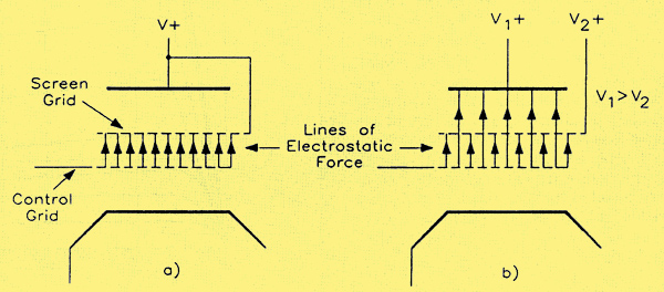
Lines of electrostatic force in a tetrode valve when (a) anode and screen grid are at the same potential; (b) anode is at a higher potential than the screen grid.
The action of the screen grid is as follows. Since it is connected to a positive potential, electrostatic lines of force will exist between it and both the cathode and the control grid, since the latter electrodes are at lower potential. Further, since its potential is, in turn, lower than that of the anode, there will also be electrostatic lines of force between the screen grid and the anode. In both cases, the direction of the lines of force is towards the anode. Since the screen grid has a positive potential, it seems reasonable that it would act, in effect, as a collector of electrons, rather like the anode. This is true; however, there is a significant difference between the construction of the screen grid and the anode. Whereas the latter is usually of solid form, e.g., made as a cylinder from a pair of plates, the screen grid is of open mesh construction, like the control grid. As a result, the electrons moving towards both the screen grid and the anode will have such a degree of momentum that they will tend to pass between the open wires of the screen grid and continue on their way to the anode, where they will be collected in the usual way. Some electrons will, of course, be collected by the wires of the screen grid, giving rise to a flow of screen current, Is. As a result, the current flowing in the cathode lead is no longer the same as that in the anode lead, as it is in the case of triodes, but is equal to the sum of the screen grid and anode currents. Denoting the cathode current by Ik, we have the Kirchhoffs Law relation that:–
Ik = Is + Ia
This concept of lines of force between the various electrodes can be used to understand how the introduction of the screen grid reduces the anode-grid capacitance.
First of all a fundamental fact needs to be considered. If it is possible for electrostatic lines of force to exist between two conductors, then self-capacitance exists between those conductors.
Suppose that the screen grid and the anode were at the same potential. All the lines of force emanating from the control grid would land on the screen grid; none would reach the anode (a) on the diagram above. Consequently, there would be no capacitance at all between control grid and anode; the screening would be complete. Obviously, in this situation, because the anode and screen grid are at the same potential, there cannot be any lines of force between them. Thus, while there must be some stray capacitance between the control and screen grids (of no significance in this context), there will be none at all between control grid and anode. When the anode has a higher potential than the screen grid, as is usually the case, there will be some lines of force between control grid and anode (b) above, thus giving rise to a small value of Cag, but most of the lines of force arising from the control grid will terminate at the screen grid. The order of reduction in the value of Cag possible by introducing the screen grid is about 1000:1, a very real improvement. Typical values of Cag for tetrodes are in the range 0.001 pF to 0.02 pF.
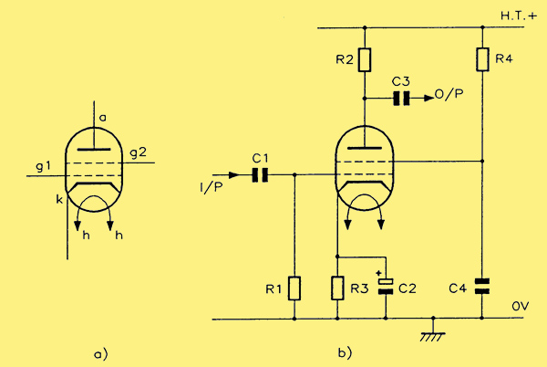
(a) circuit symbol for a tetrode valve; (b) circuit connection for a tetrode valve.
The image above at (a) shows the circuit symbol for a tetrode valve while (b) shows the circuit connection for such a valve. The actual screen voltage may be derived by means of a potential divider (with the lower section bypassed by a capacitor) or, as shown in the figure, by a series dropper resistor R4, with a capacitor C4 decoupling to 0 V in order to 'ground' the screen grid (as far as AC is concerned). Typically, the screen voltage is set at about two-thirds of the anode supply voltage, though there are, of course, exceptions.
Tetrode Characteristics and Parameters
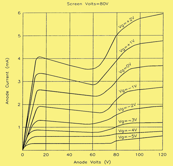
Anode characteristics for a tetrode valve.
Above is a set of anode characteristics for a typical tetrode valve, and it will be immediately apparent that these are dramatically different from those for the triode. Rising steeply and quite linearly at first, they then show a region of negative slope before rising again, this time in a non-linear fashion. The initial range of linear voltage/current variation is very limited in the example shown, terminating at a value of anode voltage that is slightly less than 10 V. By comparison, the region of negative slope goes up to about 60 V and has a significance that is not immediately obvious. Consider what is happening in terms of the voltage and current changes in the anode circuit over this range of anode voltage. The graph shows that, as the anode voltage increases, the anode current actually decreases. This may not be the sort of behaviour we would expect, but there is a good reason for it. However, before investigating such a reason, consider the value of anode slope resistance ra in this region.
We know that the value of ra is obtained by dividing an increment in anode voltage by the corresponding increment in anode current, these increments being taken from one of a set of anode characteristics of Va/Ia for various values of Vg, such as those shown in the curves above. Expressed mathematically:–
ra = (delta Va) / (delta Ia)
Which ever of the characteristics we consider, there is a substantial range of anode voltage and current whence, giving specific values for delta Va and delta Ia, we find that the increment delta Ia is negative. Thus, the quotient delta Va / delta Ia will, over this range, itself be negative. Since this is equal to ra, the latter will have a negative value of resistance over this range of anode voltage and current. While this has no real use when the device is used as an amplifier, it does allow it to function as an oscillator of a particular type, since the implication inherent in the concept of a negative resistance is that, far from introducing the losses into a circuit that resistance normally does, it must actually be able to compensate for some losses in that circuit. This we know to be essential to the operation of an oscillator, since continuous oscillations can only be maintained when the losses inherent in the frequency determining components (whether LC or RC combinations) have been made good. An LC oscillator using a tetrode valve did exist, and was known as a 'dynatron oscillator'. The discussion of these implications from the shape of the tetrode's anode characteristics does not, however, explain how that shape arises in the first place of course. For that we must look at another phenomenon known as secondary emission.
Secondary Emission
Cast your mind back to Electron Emission, where we introduced the various methods for making a material emit electrons. The most common and easiest method, as was shown shown, is where the cathode surface of a valve emits electrons because of its high temperature; this makes it possible for some electrons to attain such high energy levels that they are able to escape from the material. However, this is not the only way in which electrons can be emitted from materials. Other methods include secondary emission, high field emission and photoelectric emission. The first of these, secondary emission, occurs in a tetrode valve, and it is this effect that is responsible for the curious shape of the anode slope characteristics seen in the tetrode curves, and which actually makes the tetrode unsuitable as an amplifier; it would seriously distort each negative half-cycle of the signal.
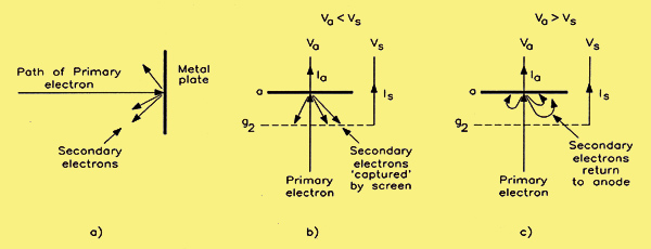
(a) the principle of secondary emission; (b) secondary emission in the tetrode when Va LT Vs and (c), when Va GT Vs.
When electrons strike a suitable surface at high velocity, secondary electrons will be emitted (a) above. This is true of both conductors and insulators. The number of secondary electrons emitted depends upon the velocity of the primary electrons striking the surface and the nature of the surface itself. As a rough indication, a pure metal surface may yield three secondary electrons for each primary one when the conditions are right. It is possible to fabricate surfaces that will produce figures of 10 secondary electrons per primary electron. Naturally, this would normally be done in circumstances where we wish to enhance the effect. Such is not the case in the instance of the tetrode valve. Here the phenomenon arises from the nature and the construction of the device and is quite accidental. What we need to consider is not how to make use of this secondary emission, but how to eliminate its effect!
In the case of the tetrode, there are two electrodes where secondary emission can occur. These are at the screen grid and at the anode, that is to say, either of these electrodes can be bombarded by primary electrons (originating at the cathode) to yield secondary electrons. What happens to these secondary electrons depends upon the relative potentials of screen grid and anode.
Suppose that, in the first case, the anode has a lower potential than the screen grid. The secondary electrons produced at the surface of the anode will be attracted to the screen grid; this will increase the flow of current Is in the screen grid circuit. If instead we assume that the anode has a higher potential than the screen grid, then the secondary electrons produced at the screen grid will be collected by the anode, this time producing arise in the anode current Ia. These situations are illustrated in (b) and (c) above. This interchange of electrons between anode and screen grid is superimposed upon the flow of primary current between the cathode and these two electrodes. It commonly occurs at potentials of between 25 and 75 V. At potentials less than 25 V, the primary electrons have insufficient energy to produce secondary emission. At potentials greater than 75 V, secondary emission takes place, but the potential of the emitting electrode is high enough to attract the secondary electrons back immediately.
In a nutshell, then, where in the diagram of tetrode curves the anode voltage is less than 10 V, anode current rises in proportion to anode voltage. Between 10 and 70 V, secondary emission from the anode, by its being bombarded with what are now higher energy electrons from the cathode, causes an electron flow from the anode to the screen grid, 'stealing' a proportion of anode current, so anode current falls. When the point is reached where anode voltage is equal to the screen grid voltage this cannot happen, and then when the grid is less than the anode, secondary emission from the screen grid takes place, but is so small as to be practically insignificant, or is suppressed.
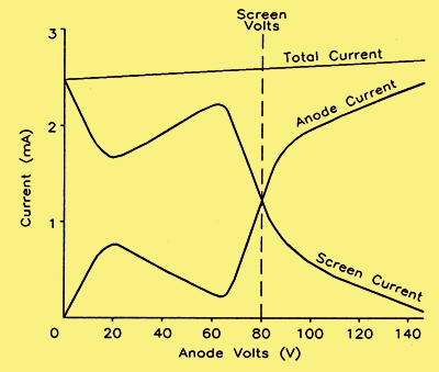
Variation of screen grid current and anode current with anode voltage for a screen grid (tetrode) valve.
The voltage and current relations can be seen more clearly in the above diagram. In this diagram, we have plots of all three valve currents against anode voltage as a common parameter. As we would expect from the previous discussion, the shapes of the anode and screen grid current curves are mirror images of each other. This being so, naturally the cathode current is a constant, since it is the sum of the other two currents. This cathode current is often known as the total space current. To be absolutely correct about it, as the curves show, the curve for this total space current is not quite horizontal but has a slight positive slope, showing that an increase of anode voltage does produce some increase in total current through the valve. A further point to note about the shape of anyone of the curves of anode current against anode voltage is that, once the anode voltage is greater than the screen grid voltage, the anode current is very nearly independent of anode voltage. This is an important characteristic – one that should cause us no problems, since the collector current and collector voltage in a bipolar transistor have the same form of characteristic once the collector voltage is past the 'knee' of the curve. However, in the case of the transistor, the knee occurs at a very low voltage value, a fraction of a volt in fact, and it is not difficult to avoid operation in this area. By contrast, the only way to use a tetrode as an amplifier with no significant distortion is if we ensure that the anode voltage never falls below the value of the screen grid voltage, a value that may typically be 80 V or more.
Advantages of Tetrodes. The primary aim of the tetrode is the reduction in the stray capacitance between output and input circuits of the valve. This object is satisfactorily achieved, and figures for the reduced values of Cag have already been given. Further advantages are higher values of the valve parameters, specifically μ and ra. Whereas the value of ra for triodes is usually only measured in tens of kilohms or less, the corresponding values for tetrodes are more likely to be of the order of hundreds of kilohms or even megohms. Even though gm may only be of the same order as for triodes, the product of a nominal gm and a very high ra naturally gives a very high value of μ the amplification factor. As a result, the voltage gain of tetrode amplifiers (and their derivatives) can be very much higher than in the case of triodes. What we have is not just a valve with extended bandwidth, but also one with superior gain. If only the distortion could be got rid of.
|