|
The Cathode Follower
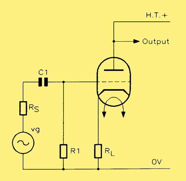
The cathode follower
This circuit, shown in above, is the valve equivalent of the emitter follower and has the same advantages. The load Rl. is in the cathode lead. The grid leak resistor and the input coupling capacitor are required as before. The grid bias voltage is derived in exactly the same way as for other valve amplifiers, by the DC voltage drop across a resistor in series with the cathode. However, since the value required for Rl might not be compatible with the resistor value calculated for the bias voltage, one or other of the two arrangements shown below may sometimes be used.
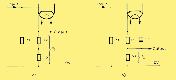
Biasing the cathode follower: (a) load value greater than bias value; (b) bias value greater than load value.
In (a) above, the load resistor comprises two resistors in series, (Rl = R2 + R3), because the value calculated for the cathode bias is less than that required for the load. In this case the DC bias voltage is developed across R2 and the grid leak is returned to the junction of R2 and R3 instead of to 0 V.
In (b), the load resistor has to have a smaller value than that required for developing the bias. In this case, the total resistance of R2 and R3 in series is used to obtain the bias voltage (grid leak returned to 0 V) and R2 is short-circuited to AC by capacitor C2 so that only R3 acts as the load for the amplifier. These latter arrangements are to be preferred to ensure that the output is not less than the input level, which is likely in the circuit at the top of the page.
The input impedance of a cathode follower is very high (though in practice it may be limited by the presence of the grid leak across the input), while the output impedance is very low. It is essentially an amplifier with l00% negative feedback, so the gain drops to less than unity while the bandwidth increases in inverse ratio.
A circuit was designed using the criteria that Ia = l0 mA; Va = 150 V, giving a grid bias voltage of -0.6 V (taken from the mutual characteristic for the ECC81). The value of cathode bias resistor calculated from this data is 60 Ω (0.6 V / 10 mA) and a standard value of 56 Ω was actually used. This is R2 in the circuit below.
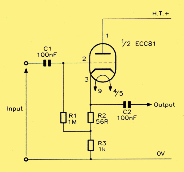
Design for a cathode follower.
To allow a reasonable signal swing, it was decided to set the cathode potential at + 10 V; thus R3 would need to be about 1kΩ in value. The circuit above was hooked up and tested. In practice, the anode current turned out to be 7.7 mA, setting the cathode potential at + 8.6 V. The gain was measured as 0.83 at the mid-band (1 kHz). The bandwidth was too wide to be measured with the available signal generator but, as an indication of how far the bandwidth is extended, the gain (relative to 1 kHz) fell by 0.6 dB at 5 Hz and by 0.4 dB at 500 kHz.
|