|
The Pentode Valve
The pentode, as the name implies, has five electrodes. Four of them are exactly the same as for the tetrode, but the extra fifth is called the 'suppressor grid', and it is located between the screen grid and the anode.
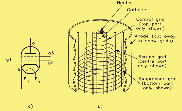
The pentode valve (a) circuit symbol; (b) physical construction.
The circuit symbol and physical construction for a pentode valve are shown. The suppressor grid is usually connected directly to the cathode, often internally within the valve envelope, but some times an external connection is allowed for. The function of this additional grid is to create a lower voltage region (a negative electric field) between the screen grid and the anode, and this prevents the interchange of secondary electrons between these two electrodes. As a result, the pentode retains the advantages of the tetrode in terms of its high amplification factor and ability to operate at high frequencies, but the kink in the anode characteristic is totally eliminated!
Alternative Terminology for the Grids
We have now met the most complex valve type that we shall be talking about in this brief series. We know that it has three grids, which are termed the control grid, the screen grid and the suppressor grid. Each of these is a bit of a mouthful for constant repetition, so it is common to refer to them simply as: the grid, screen and suppressor, respectively. However, when it comes to annotating valve base diagrams, even these abbreviated titles occupy too much space and an alphanumeric reference is used instead. In this system, the three grids are called gl, g2 and g3, respectively. These symbols, together with h for the heater, k for the cathode and a for the anode are used in the base diagram for an EF86 pentode shown below.
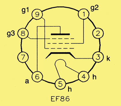
Base diagram for the EF86 pentode.
Pentode Characteristics
Mutual and anode characteristics for the CVl38 (EF91) pentode valve are shown below.
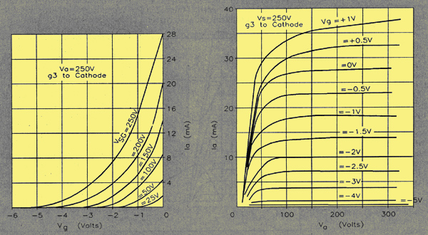
(a) mutual characteristics and (b) anode characteristics for the EF91 pentode valve.
Note that these are typical curves for the conditions stated. The screen volts are set fairly high at 250 V and the suppressor is strapped to the cathode. The mutual characteristics show that this valve is what is known as a short grid base type, by which is meant that a relatively small negative grid bias voltage is required to cut it off, even with quite high anode potentials. For example, with an anode voltage of +200 V, only -5 V is required on the grid to cut the anode current off completely. If the screen potential is reduced to 200 V then the cut-off point is reached with -4 V on the control grid. Again with the anode held at 200 V.
Amplification Factor
The value of the mutual conductance, gm, for pentodes is similar to that for triodes. However, as is the case with the tetrode, the value of ra for the pentode is extremely high, leading to a high amplification factor. It is useful to look at the case of the EF91 to see how superior is its performance as a high gain amplifier compared with a triode.
For the EF91, the three parameters are:
gm = 7.5 mA/V; ra = 1 MΩ; μ = 7500.
Compare these parameter values with those for the 12AT7 (ECC81) double-triode:
gm = 4.8 mA/V; ra = 12 kΩ; μ = 57.
Suppose we were to use these respective valves as voltage amplifiers with the same value of anode load (say 47 kΩ) in both cases. Since the VAF is given by:
VAF = (μ x Rl) / (ra + Rl)
Then for the respective cases; we should get the following results.
(i) Triode amplifier (using 1/2 ECC81):
VAF = (57 x 47) / (12 + 47) (working in kΩ) = 45.41
(ii) Pentode amplifier (using EF91):
VAF = (7500 x 47) / (1000 + 47) (working in kΩ) = 336.68
Thus, using the same value of anode load in both cases, the pentode has an edge of 336.68/45.41 = 7.4:1 in terms of its ability to amplify a signal voltage, compared with the triode.
Variable-μ Valves
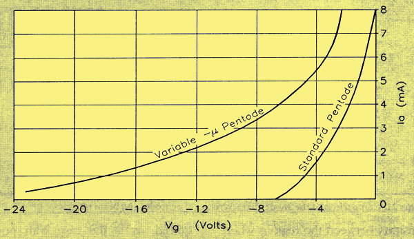
Mutual characteristics for variable-μ and short grid base pentodes.
It is often desirable to be able to control the amplification of a valve, either manually or automatically (as in the case of AGC in radio receivers). This is done by constructing the valve in such away that the mutual characteristic shows a very gradual cut-off, leading to the obvious inference that the slope of this characteristic varies widely from a high value at small negative grid bias values to a low value at large negative bias values. Such a characteristic is shown above, where the mutual characteristic of a normal short grid base pentode is included for comparison. Since the slope of the mutual characteristic is equal to the parameter gm, then it is gm that is actually varying as the grid bias voltage is varied. But, since μ is proportional to gm, then μ also varies with the grid bias voltage.
In practice the way that the construction of a variable-μ valve differs from that of a standard pentode is in the spacing of the control grid wires. In a normal valve, they are equally spaced, whereas in a variable-μ valve the spacing gradually changes from being closely spaced at the centre to being wider spaced at the ends. In use, the rectified IF at the detector end of a radio is returned as negative DC to the signal grid of the variable-μ valve via its grid bias resistor. Since this negative bias increases as a result of an increase in the IF signal level at the detector, from a corresponding increase in received RF at the tuner-head, gain is reduced. The variable-μ valve would often be the first IF stage.
|