|
A Valve Power Supply
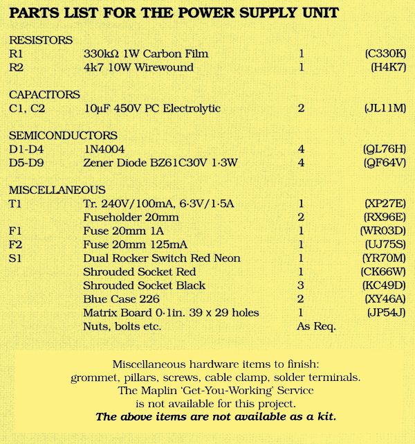
Compared with solid state devices, valves need much higher voltages although at very much smaller currents. This reference is to the HT voltage, of course (HT = High Tension, as it was known). The heater supply will be 6.3 V at, often, several amperes. This requires a specialised transformer, which must have both a low voltage, high current winding for the heater supply, as well as a high voltage secondary winding for the HT. Such a specialised transformer was made available and could be found in the Maplin Catalogue of the time. This has a 240 V 100 mA secondary and a 6.3 V 1.5 A secondary. Thus it is capable of supplying the heaters of five valves if each is rated at 6.3 V 0.3 A, as are the double-triodes described earlier.
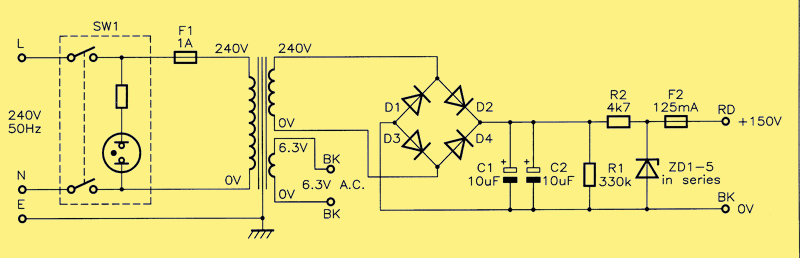
Circuit diagram for a simple stabilised power supply.
There are some fundamental problems in the design of valve-based equipment these days, due to the fact that much of the supporting hardware is simply no longer available. In the days when valve designs were current, appropriately rated capacitors were available in a wide range of values. For example, the reservoir capacitor for a valve power supply would have a value of about 16 μF with a voltage rating of 350 V DC or 450 V DC. Moreover, such a component would be quite large physically. Today, in the Maplin Catalogue, there is only one component that gets anywhere near matching this specification and that is a 10 μF 450 V DC item. However, on the plus side (pardon the pun) it shows that technology has apparently advanced such that this current item is a fraction of the size of its forebears (which used to be tall. aluminium cans mounted vertically on top of the chassis with the aid of capacitor clips, their tags made accessible beneath via a round cut-out); it is also very cheap. Thus the design uses two of these in parallel in order to get a total capacitance of 20 μF. The ripple rating of these capacitors is 280 mA. which is more than adequate for this modest design.
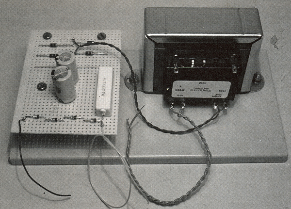
The valve power supply, with transformer and circuit board on sub-chassis.
The rectifier needs to have a voltage rating to match the 340 V peak secondary voltage available and. for this purpose, a bridge has been constructed from four discrete 1N4004 rectifier diodes, which are conservatively rated for this purpose. So far, the design yields an unregulated DC voltage of 340 V DC across the reservoir capacitor. It was thought that this was far too high for the experimental purpose for which it was intended. and so it was decided to add a simple shunt regulator using series-connected Zener diodes to perform two useful functions – dispose of the excess DC voltage and obtain a stabilised supply with a nominal output of 150 V. It was decided to use four 36 V Zener diodes. giving 144 V at the full-load output current of 30 mA. Although higher voltage Zeners are available. this would limit the possible output current further since all diodes in the available range have a power rating of only 1.3 W. The design of the shunt regulator means using a series resistor capable of dropping some 200 V at 36 mA (the extra 6 mA keeps the Zener diodes in conduction when full load current (30 mA) is being drawn. The calculated power rating is about 7 W and an appropriate wire-wound resistor is used.
A case was chosen from the Maplin range, which had its own separate chassis. This is conveniently sized and allows the transformer and a small piece of matrix board (no copper strips) to be mounted in it and wired prior to installing it in the case and connecting it up to the case-mounted components.
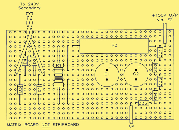
Layout diagram for the power supply circuit board. Component leads are hard wired on the underside of the matrix board.
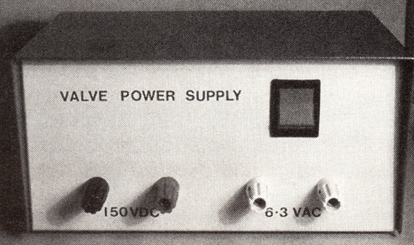
The diagram above shows the layout of the circuit on matrix board, and the photographs show the layout used for the front panel and rear panel components, the latter being separate fuses for the mains input (1 A) and HT output (125 mA). A neon double-pole rocker switch is used for power on/off, and 'touch proof' 4 mm sockets are used for the LT and HT outputs. Use red and black sockets for the HT output and two black sockets for the LT output. The prototype used 4 mm terminal posts, but it is strongly recommended that 4 mm 'touch proof' sockets suggested are used for reasons of safety. It is also recommended that a high voltage warning label is applied to the unit.
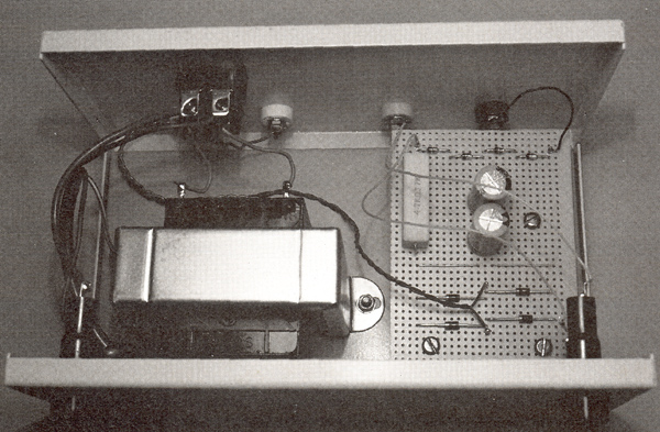
Interior view of DC power supply: note separate fuses for mains input and DC output.
It is important that the case and transformer are properly earthed, this can be achieved by using a solder tag; secure it to one of the transformer mounting lugs by means of a nut, bolt and shake-proof washers. It is important that any varnish is removed from the mounting lug so that a sound electrical connection is made. The incoming mains cable earth wire should be soldered to the tag. All connections within the PSU should be suitably insulated. The HT output is floating but the 0 V side of the regulated DC output can be earthed if required by strapping it to this terminal. Alternatively. a further front panel 4 mm terminal post could be added (connected to the solder tag) to allow earthing of the HT supply at will. To illuminate the neon in the rocker switch. the mains wiring should be made as shown below.
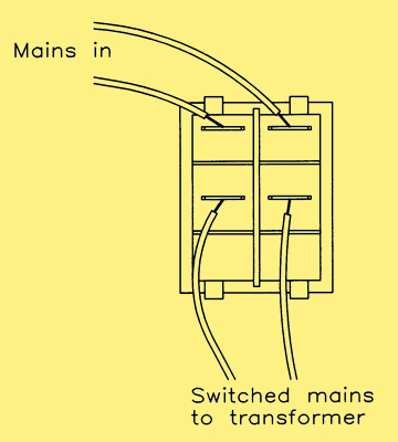
Wiring of the double-pole rocker switch. Connections must be insulated.
Output Ripple Voltage
The unit was tested when built and loaded to full capacity on the HT side by drawing the full-load current of 30 mA. The output voltage was measured as 144 V and the ripple at this loading was less than 0.2 V Pk-to-Pk. For the output voltage quoted this is less than 0.14 %. so is not of any significance. Note: The power supply is not designed for continuous use with the output unloaded.
A Valve Regulated HT Supply
by Mike Holmes
The valve supply transformer used (Order Code XP27E) can deliver a greater HT level than the design above – up to 340 V unregulated – and a higher regulated output is therefore possible, i.e.. nearer the accustomed 250 V level, which is more practical for most working valve circuits.
An alternative regulator circuit that I developed into two variations is now presented. In keeping with the 'tradition', the circuit is, naturally, built around a valve. The valve used is a Mullard ECL82, a triode output-pentode with a B9A base, once very commonly found in 'cheap-and-cheerful' record players, radios and radiograms.
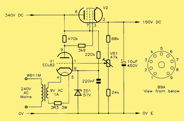
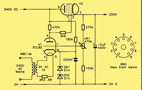
A 150 Volt valve regulator.
The circuit of the 150 V variation or the regulator is shown above. At first sight. this is somewhat confusing to follow. so the easier to understand transistor equivalent is shown below.
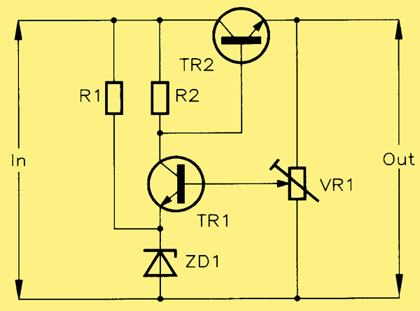
The transistor equivalent of the 150 Volt valve regulator.
As a thoroughly conventional supply regulator. it has three distinct stages: In the transistor circuit these are a precision voltage reference (ZD1 and Rl); a control amplifier (TR1 and R2); and a series pass element (TR2). VR1 taps off a proportion of the output to the inverting input of the control amplifier (base of TRl). Adjusting VR1 alters this ratio and, hence. is used to trim the output with reference to the precision source.
Transposing this arrangement to the valve circuit, you will see that the voltage reference is identical – being ZD1 provided with current from the unregulated HT via a 220 kΩ resistor. with any AC noise bypassed to 0 V by the 220 nF capacitor. V1. The triode section of the ECL82. is the control amplifier, with 470 kΩ resistor as an anode load. The series pass element is the power pentode section. V2. Here, the screen grid is directly connected to the anode, so it actually behaves as a high-current triode in cathode follower mode.
The circuit simply replaces R2. and ZD1 to ZD5, in the original design shown at the top of the page, where 340 V DC. connects to the plus side of C2 (10 μF) (where R2 used to be). VR1 is set to an approximate mid position prior to powering-up. and once warmed up and an output has been obtained. is used to trim the output to 150 V; as monitored by a voltmeter. The output can be up to 20 mA, and so it is ideal for small amplifiers requiring a smooth and steady supply, free of mains noise and fluctuations – useful for an audio preamplifier, perhaps?
A 250 Volt valve regulator.
The design was taken further to produce the 250 V regulator shown above. There are only subtle changes to some resistor values, due to different voltage levels, and two Zener diodes used in series for a reference of 102 V instead of 51 V in this case, VR1 has more scope, and so the regulator can form the basis of a variable output power supply. All the resistors can be normal 0.6 W metal film types, and VR1 is an ordinary, enclosed preset. The 220 μF capacitor is a 250 V polyester type, and the zener diode is a BZY88C51V. Wiring-up around the B9A socket can be done with the help of a tag strip or tag board.
Of course, in the old days, Zener diodes did not exist, and so precision gas-filled tubes would have been used commonly known as 'voltage stabilisers' One experiment to duplicate this, using a wire-ended neon lamp in place of the Zener(s) (RX70M), proved quite successful. With the neon holding steady at about a constant 80 V.
The only real complexity that the regulator adds to the circuit is its heater power requirement. Unfortunately, it should not be taken directly from the main transformer's heater secondary; this is for two reasons. Firstly, the ECL82 draws 780 mA of heater current, which is most of the heater secondary capacity (which is better employed heating several other valves!). But, more urgently, there is the matter of the large potential difference between the two cathodes of the ECL82. For the 150 V regulator, this will be 99 V; for the 250 V version, it will be 148 V: Between these potentials is the common heater circuit of the valve which, if connected to 0 V at some point, puts a stress between the cathode of V2 (pentode section) and its heater filament to the tune of the total output HT level! The way round this is to have a dedicated heater supply circuit, which must be fully floating. i.e. not earthed at any point. In this case, the average cathode-to-heater potential will be 49.5 V (150 V output), or 74 V (250 V output) for each section, which is much more survivable. A second mains transformer (WB11M) has two 9 V secondaries wired in parallel for a 1 A total output, and a 3.3Ω 3 W resistor in series, to drop the voltage down to 6.3 V
See also Current Limited 0-200V Power Supply.
|