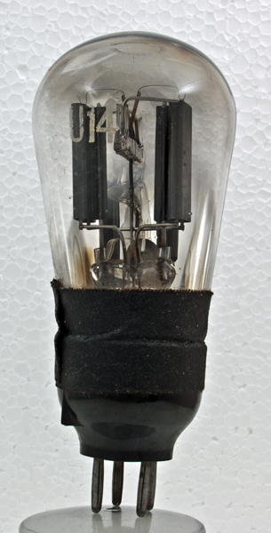
Initially the U14 and the U12 were the same valve intended to meet all HT requirements up to a maximum of 120 mA at 500V, using a capacitor-input filter. However, some valves performed better than others on final factory test so the best ones were graded and marked U14 whilst the also-rans were marked U12.This U14 was designed to work with a maximum reservoir capacitor of 32 µF and to have an effective series resistance of 100 Ohms.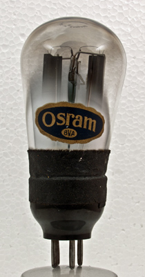
This U14 has the earlier balloon envelope but also solid anodes.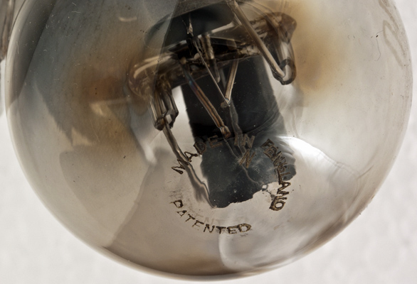
The dome of the envelope has etched markings but nothing in the centre of the circle.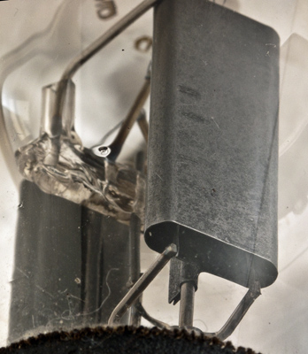
The lower end of one anode and the glass rod support in the centre.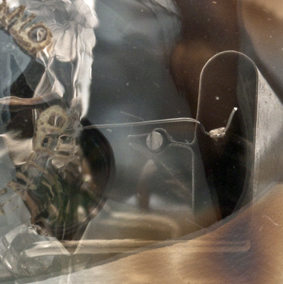
One rectifier segment: the ribbon filament and its support spring.The balloon envelope is 57 mm in diameter and, excluding the B4 base pins, is 117 mm tall.References: Data-sheet & private communication. Type U14 was first introduced in 1931. See also 1931 adverts. |