|
No higher praise can be given to the superhet receiver described under the name of the New lMonodial Super than that it excels in performance in almost every direction the original Monodial described in The Wireless world. The original Monodial is still regarded by the thousands Of constructors who have built it as the finest receiver which has appeared in this country, yet now. The Wireless World beats its own record by the production of a new design which; whilst based on the original set, incorporates every new idea of practical value in superheterodyne technique.
The problem of obtaining both high selectivity and realistic reproduction is by no means easy of practical solution. The use of highly selective circuits in conjunction with tone-correction [★] For home construction Wireless World chose to have 110 kHz as the IF for ease of alignment. Commercial receivers had adopted 455 kHz with IF bandpass tuning as this retained the higher audio frequencies. enables intelligible interference to be reduced to a negligible amount without detriment to the quality of reproduction, but this cannot be said of sideband heterodyning. There is, indeed, no known way of avoiding this form of interference which does not at the same time restrict the high-frequency response of the receiver.
In the past the difficulty has been overcome by fixing a definite upper limit to the frequency response at about 5,000 Hz. With this limit really good quality can be obtained and sideband splash is reduced to modest proportions. The quality, however, is not the best obtainable and the remaining interference is all too noticeable. Fortunately, sideband splash does not occur on all stations, and on the stronger transmissions it is often absent. Obviously, therefore, the solution to the problem lies in providing alternative receiver characteristics.
The Latest Technique

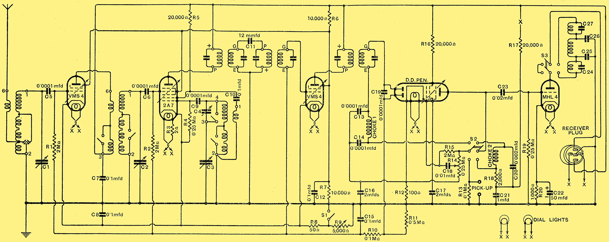
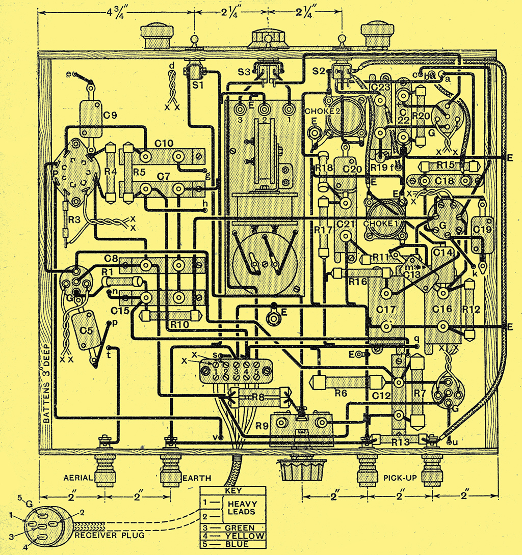
Fig. 1. - The receiver circuit diagram.
Valves used are: VMS4, 2A7, VMS4, DDPen & MHL4.
Fundamentally, the receiver should be designed to provide a level frequency response up to some 7,000 or 8,000 Hz, for this is sufficient to provide the best quality with the vast majority of present day loud speakers, and further extension of the response would result in needless expense. Means should be provided for restricting the response to about 3, 500 Hz, however, when it is desired to listen to stations suffering from sideband heterodyning.
A modern superheterodyne, therefore, must. be fitted with an adjustable frequency response, but development does not stop here, and no part of the receiver is completely free from change. Automatic volume control has now become a necessity, and one of the simplest means of achieving it lies in the use of a valve of the duo-diode-pentode type for the second detector. With such a valve, not only are the initial stages controlled, but the first LF stage also, with the result that the system can become practically perfect.
The IF circuits, too, are changed, although this is not apparent from the circuit diagram. The alteration lies in the degree of coupling adopted in the transformers, for now no attempt is made to obtain a double-humped resonance curve, and tone-correction is relied upon entirely for the preservation of the upper musical frequencies. This change results in an increase in selectivity, but has been made primarily with a view to the simplification of the initial adjustments, since without elaborate apparatus it has been found difficult to adjust true bandpass circuits in such a way as to avoid obtaining an asymmetrical resonance curve.
The most striking modification, however, lies in the frequency changer, for the introduction of the special pentagrid converter has enabled an improved performance to be obtained with one valve less than in other arrangements. The use of this valve enables interaction between the signal frequency and oscillator circuits to be avoided, with a consequent simplification of the ganging, it reduces the cost, it leads to greater efficiency, and, most important, it greatly reduces the possibility of whistle production.
Pre-Selector Circuits
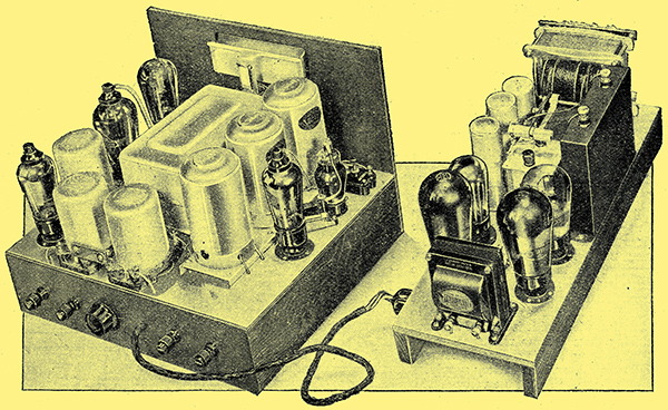
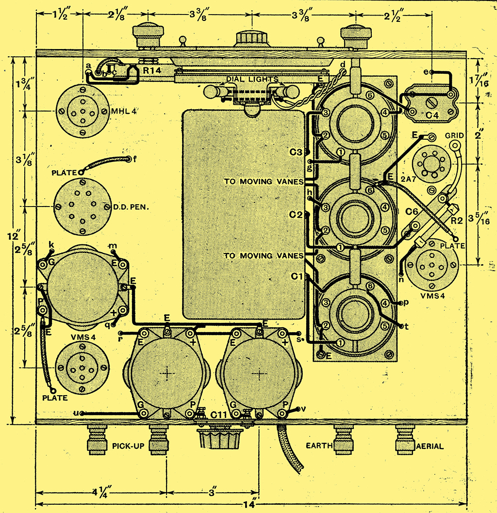
The pentagrid frequency-changer valve may be seen on the right-hand side of the receiver chassis and it should be noted that its holder is mounted on the under side of the base.
The application of the latest developments to the superheterodyne have thus resulted in striking changes, and the circuit diagram of the receiver unit will be seen in Fig. 1. The HF valve is preceded by a single tuned circuit, and its grid bias is applied through the 2M Ω resistance R1, the 0.0001 μF capacitor C5 serving to couple the grid to the tuned circuit. The coupling between the HF valve and the frequency changer is by means of an HF transformer, and the control grid of the pentagrid is again biased through a 2M Ω resistance R2, the signal being fed through the 0.0001 μF capacitor C6. The two signal frequency tuned circuits are tuned by two similar sections, C1, C2, of the three-gang tuning capacitor.
The inner grid of the pentagrid is joined to the oscillator tuned circuit through the 0.0001 μF capacitor C9, and its bias is derived by the flow of grid current through the 0.25 MΩ resistance R4. The tuned circuit is of the conventional type and is tuned by the shaped-plate section C3 of the gang capacitor. The 0.002 μF padding capacitor C4 is inserted on the long waveband for the maintenance of ganging. The reaction coil is shunt fed by the 0.1 μF capacitor C10 and the 20,000 Ω resistance R5.
The primary of the first IF transformer is included in the pentagrid anode circuit, and its secondary is coupled to the primary of the second transformer by a 12 pF capacitor C11, this loose coupling being necessary in order to avoid a double-humped resonance curve. The secondary of this transformer feeds the variable-μ IF valve, in the anode circuit of which the third transformer is connected.
The AVC System
The secondary of this transformer feeds the two diode anodes of the duo-diode-pentode which serves as the second detector, the AVC valve, and as the tone-corrector. One anode is fed directly from the tuned circuit, and it provides the rectified LF output and the bias for the pentode portion of the valve through the IF filter Ch1, C13 and C14, the potentiometer R14 of 0.25 MΩ serving as the manual volume control and also as the diode load. The other diode provides delayed AVC for the HF, frequency changer, and IF stages; it is fed through the 0.0001 μF capacitor C19, and its load is the 0.5 MΩ resistance R11, and the AVC voltage developed across this resistance is applied through the filter comprising R10 and C15 to the grids of the controlled valves. The necessary delay voltage is provided by the voltage drop across the 100 Ω resistance R12, which is shunted by a 2 μF capacitor C16.
The DC voltage due to the rectification of the signal is fully applied to the pentode control grid through the 2 MΩ resistance R15, and any.desired proportion of the LF voltages through the 0.01 μF capacitor C18. On gramophone the connections are changed, and the pick-up is connected between the upper end of the volume control and the earth line. The fixed negative grid bias is then nearly equal to the potential across the delay resistance R12.
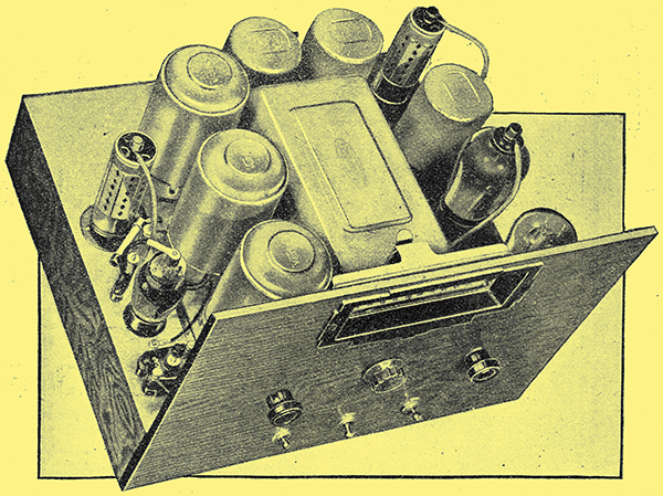
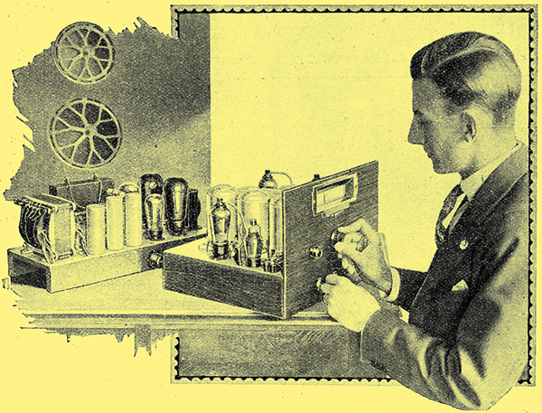
This view of the receiver unit clearly shows the clean layout and the full-vision tuning dial.
LF Circuits
The tone-corrector is fitted as the inter-valve coupling, and on radio it consists of the 0.25 H choke Ch2 in series with a 2,000 Ω resistance R18, the 0.002 μF capacitor C20 being joined across the combination. It, is thus a tuned anode circuit resonating at 7,000 Hz, and giving a fiat response curve over the lower and middle frequency ranges. Such a characteristic is quite unsuited to gramophone reproduction, and so the radio/gramophone switch changes over the connections. On gramophone the coupling consists of the 2,000 Ω resistance R18, shunted by Ch2 and C20 in series; these components then act to some extent as a scratch filter.
The pentode screen is fed from the 200 Volts line through the 20,000 Ω resistance R16, with a 2 μF capacitor C17 connected to earth. = The anode circuit is decoupled by another 20,000 Ω resistance and the 1 μF capacitor C21; this capacitor also acts to give a rising characteristic in the extreme bass to compensate for the inevitable slight loss of bass occurring in the RC couplings.
The inter-valve coupling to the MHL4 LF valve is completed through the 0.02 μF capacitor C23 and the 0.25 MΩ resistance R19. This valve is biased by the 1,000 Ω resistance R20, shunted by a 50 μF electrolytic capacitor C22. With the switch, S3 in the upper position, the primary of the LF transformer which feeds the push-pull output stage, Fig. 2, is connected directly in its anode circuit. When the switch is placed in the lower position, however, the special low-pass filter is connected in circuit and the overall frequency response of the receiver is then limited, to 3,500 Hz for the elimination of sideband heterodyning. This filter is available as a complete unit, including the three chokes and the capacitors C24, C25, C26 and C27. It is designed for working between terminal impedances of 10,000 Ω; the input impedance is provided by the internal AC resistance of the MHL4 valve, but the output impedance must be obtained by connecting a 10,000 Ω resistance R21 across the primary of the transformer.
The LF valve anode is fed directly from the 200 Volts line, in common with the anodes of the frequency changer, and IF valves. The screens of the variable-μ type valves, however, are fed from the tapping on the potentiometer, made up from the 10,000 Ω resistances R6 and R7, connected across the HT.supply, and are by-passed to earth by the 0.1 μF capacitor C12. The cathodes of these early valves are commoned and, when the switch S1 is closed, are taken to earth through a 50 Ω resistance R8 to provide the initial bias. When S1 is open a 5,000 Ω variable resistance is connected in circuit to limit the maximum sensitivity of the set; this is primarily for reducing background while searching, for the normal condition of the receiver is one of exceptional sensitivity. The secondary purpose of, the resistance is to reduce the sensitivity for local reception, since, it the set be used with a good aerial very close to a powerful local, the AVC system may not provide sufficient control.
Mains Equipment
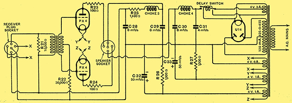
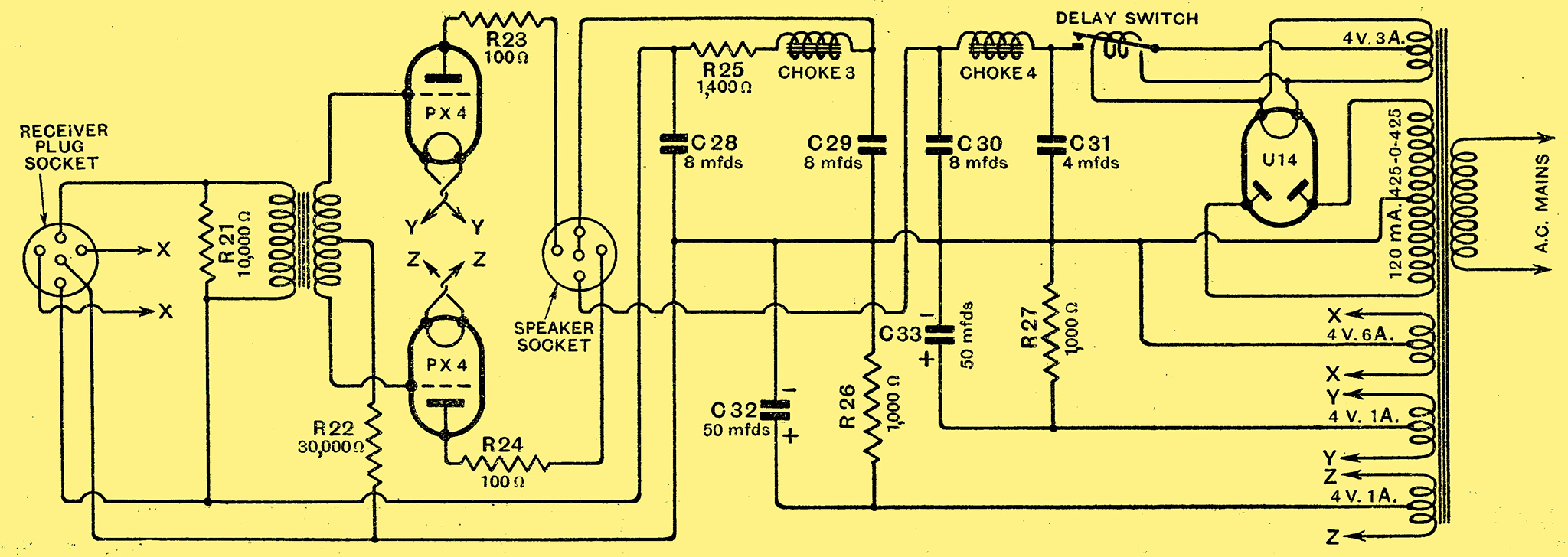
Fig; 2. - The complete circuit of the power unit is shown here; electrolytic condensers are used, not only for smoothing, but for by-passing the bias resistances and care should be taken. to connect them with their negative terminals to the chassis.
The push-pull PX4 valves are slightly over-biased so that they take only 35 mA. apiece (nominal current); as a result, the total current of the receiver falls within the 120 mA. rating of a single U14 rectifier valve. Owing to the push-pull connection, this over-biasing does not introduce distortion, for the harmonics are balanced out. Calculation indicates it that some 4 Watts output is obtainable with zero second and third harmonic distortion, and in practice some 5 to 6 Watts is obtained for the usual 5% total harmonic distortion. Decoupling of the grid circuits is likely to be ineffective in push-pull, so that the bias resistances are by-passed by 50 μF electrolytic capacitors in order to maintain the full bass response. The load impedance required by this output stage is 10,000 Ω, so that the output transformer must be of the ratio required to give this with the particular speaker employed.
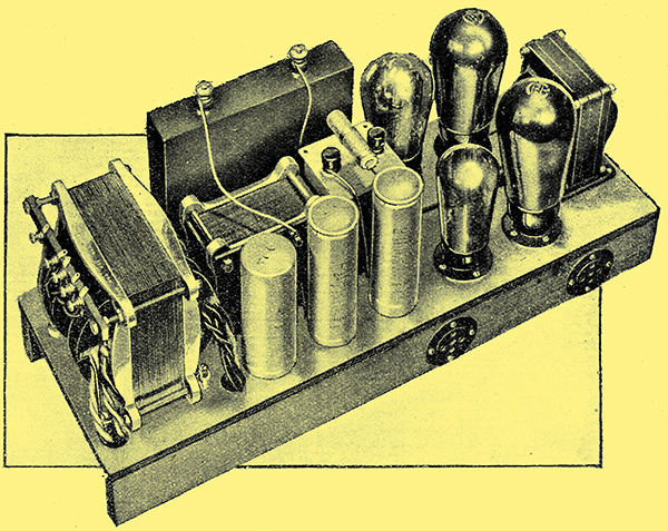
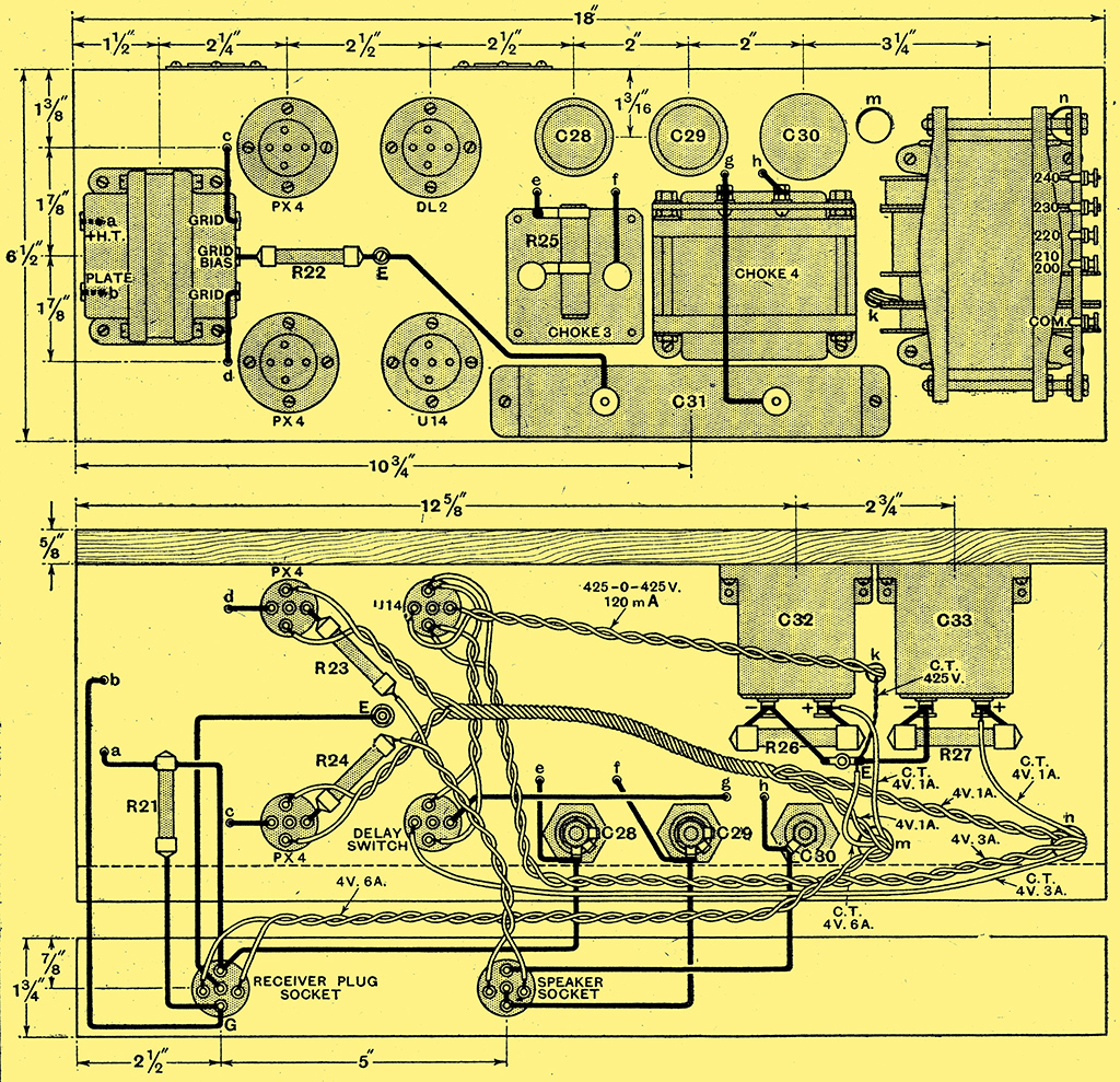
The Power Chassis.
The five indirectly heated valves and the dial lights are all run from a winding on the-mains transformer rated at 4 Volts 6 Amps; and separate 4 Volts 1 Amp windings are provided for each of the output valves. The U14 rectifier and the vacuum-type delay switch are run from the 4 Volts 3 Amps. winding and the HT secondary is rated at 425-0-425 Volts at 120 mA. The primary is tapped for mains voltages of from 200 Volts to 250 Volts, and is electrostatically screened from the secondaries.
The rectifier provides some 460 Volts un-smoothed across the 4 μF capacitor C31, and this is dropped to 443 Volts and initially smoothed by passing through the 10 H. choke Ch4. This smoothing stage is completed by the 8 μF dry-electrolytic capacitor C30. The current then passes through speaker fields, or their equivalent, having a total resistance of 1,250 Ω, and is still further smoothed in conjunction with the 8 μF capacitor C29. The potential across this condenser is about 280 Volts, and the supply for the output stage is tapped off; the current for the early stages passes through the choke Ch3 in series with a 1,400 Ω resistance R25, which, with the 8 μF capacitor C28, completes the smoothing and drops the voltage to the requisite 200 Volts.

The wiring of the power unit is straightforward, but care should be taken to connect C32 and C33 with the correct polarity.
In this way a very high degree of smoothing is obtained so that reception is completely hum-free, and yet the whole receiver can be operated from, and the field, of dual speakers energised by, a single class C rectifier valve. A maximum of economy is thus combined with a first-class performance.
The precise arrangement adopted in the new superheterodyne will now be apparent, and it remains to describe those details of the construction which are not readily apparent from the drawings and to give details of those adjustments which are essential for the attainment of the optimum performance.
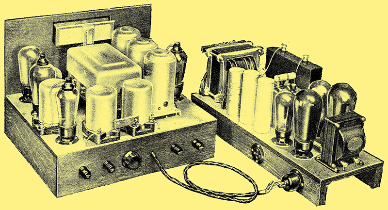
Constructional details and initial adjustments are dealt with. In spite of the exceptionally high performance of which the receiver is capable, these operations are essentially simple and need occasion no difficulty even to the inexperienced.
The receiver is constructed on a chassis built of aluminium covered plywood, which may be obtained ready built with the large holes drilled. with the exception of the valveholder for the pentagrid, the valve holders are all mounted with their main bodies on the upper side of the base, and their legs projecting through large diameter holes. No British pentagrid valve is as yet available, and the valve specified is of American origin, and is fitted with an American type 7-pin base. Consequently, an American valveholder is necessary, and this cannot readily be mounted in the same manner as the others. This valveholder, therefore, is mounted on the underside of the chassis, and the hole in the base is large enough to accommodate the base of the valve. When wiring up the circuits of this valve it should be remembered that the control grid is mounted on the top of the bulb, not the anode, as in British valves. There is no terminal on the valve, merely .a metal boss, and for the connection it is necessary to use the special clip provided. The valve is rated tor a heater potential of 2.5 Volts at 0.8 Ampere, so that it is necessary for a resistance to be included in its heater circuit. This resistance R3 has a value of 2 Ω, and the actual heater potential is slightly under 2.5 Volts.
Checking the Operation
Apart from these points, the construction is entirely straightforward, but it should be noted that it is necessary for the base to be cut away slightly to accommodate the volume control. In most places the wiring is carried out with No. 22 tinned copper wire run in small diameter sleeving, and in certain cases screened leads are used. It is important that the screened sleeving be of the type specified or of similar characteristics, and that the internal wire be no heavier than No. 22 gauge. Thick rubber-covered metal braided wire or motor car type armoured cable must not be used.
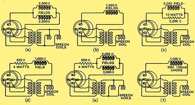
Fig. 3. - The various speaker connections for different cases are illustrated, at (a) for dual speakers with 2,500 Ω fields, at (b) for a single 1,250 Ω speaker, at (c) for a single 2,500 Ω field, at (d) for a single 1,000 Ω field, at (e) for dual 2,000 Ω speakers, and at (f) for a non-energised speaker.
The inter-unit cable must have two heavy members for the heater current, and if an excessive voltage drop is to be avoided these must be of at least 70/36 gauge and no longer than 30 in. The speaker connections will depend upon the type of loud speaker used, and six alternative arrangements are shown in Fig. 3. The output transformer employed is of importance if the best results are to be obtained; it should have a primary inductance with no DC of not less than 60 H, and be of such ratio that the average primary impedance is about 10,000 Ω. With Magnavox dual speakers this calls for a ratio of 112:1, and with Rola dual speakers a ratio of 100:1. A single Magnavox speaker, however, would call for a ratio of 79:1, and a single Rola a ratio of 70:1; the BTH RK Senior speaker needs a ratio of 25.8:1, and the Ferranti M1 a ratio of 25:1.
When the set has been switched on for a quarter of an hour or so the various voltages and currents should be checked over to make sure that they are reasonably in accordance with the figures of the Table below.
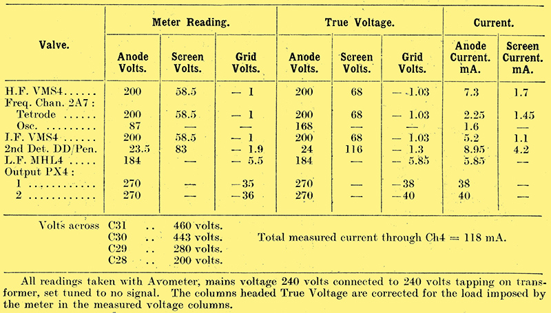
Table of Measurements.
Any wide discrepancy would indicate a defect in the receiver or a valve, but no notice need be taken of a general rise or drop in voltages by some 10%, since this may be due merely to the mains voltage being different from its rated value. Such a change in voltage, of course, would be accompanied by a similar, although usually smaller, change in current; low voltages accompanied by abnormally high currents or high voltages with low currents would show a defect in the receiver.
Preliminary Adjustments
Having made certain that the operating conditions are in order, it remains to carry out the initial adjustments of trimming and ganging, and here a milliammeter connected in the anode circuit of the DD/Pen at the point X is of great service. The meter should give a full scale deflection for 10 mA or 12 mA. At first, the IF coil couplings should be set fairly close together, and in any location it should be found possible to obtain some signal; this should be tuned in as accurately as possible, and the IF adjustments proceeded with.
The IF couplings should next be loosened as much as possible without completely loosing the signal, returning if necessary, and the coil cans replaced. Each IF trimmer must then be adjusted for maximum response. Some trimmers will be more critical than others, but a definite optimum setting on each should be obtained. If the signal is weak this adjustment must be carried out by ear, for the meter deflection will be too small to be observed. With a strong signal, however, the meter is essential, for, owing to the action of AVC, the ear is not sufficiently critical. A really accurate adjustment can only be obtained with the aid of the meter and with a strong signal.
When a rough preliminary adjustment of the IF trimmers has been obtained in this way the coil couplings should receive attention. Each coil coupling must be set for maximum signal strength, whether judged audible or by the change of current indicated by the meter. The IF circuits are now roughly adjusted, but, before paying great attention to their precise adjustment, it is as well to make sure that their frequency is correct.
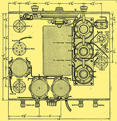 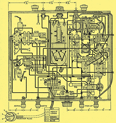
The layout of components and wiring in the receiver unit is readily apparent. It will be noted that a minimum of leads passes through the base.
The Final Ganging
If the second channel whistle is from 215 to 225 kHz lower than the frequency of the local station, the IF adjustment can be taken as correct, but if it be found to occur at some other frequency, all the IF trimmers must be appropriately altered. Thus, it is not uncommon to find that the whistle occurs on Brussels No. 1 in the London area. This means that the intermediate frequency is 127 kHz, and is too high for accurate ganging to be maintained. The frequency must be lowered by increasing the capacity of all IF trimmers, and this is accomplished by rotating the adjusting wheels all in an anti-clockwise direction when viewed from above.
When the correct frequency has been obtained, a strong signal should be tuned in so that the meter needle is deflected by several milliamperes and a change in current is easy to detect. Each trimmer can then be accurately adjusted for maximum change in current, and the couplings readjusted for the same condition. The ganging can then be similarly readjusted, using the meter as an indicator, and no difficulty should be experienced with a good aerial in obtaining a large deflection even in daylight from such stations as Fécamp and Brussels No. 1. As before, the adjustment on the low wavelength station is to the preselector trimmers, and is for maximum response, as indicated by maximum change of current on the indicating meter. On the high wavelength station the oscillator trimmer is adjusted while rocking the tuning dial for the best combination of settings. After this adjustment it is always necessary to return to the lower wavelength, and retrim the two preselector circuits.
Long Wave Ganging
When the medium waveband ganging has been completed, attention can be paid to the Long Wave adjustment. This is only to the padding capacitor C4; the tuning dial should be set to about 60° and C4 adjusted until Daventry National is heard. Huizen should then be receivable at a higher dial setting, and C4 can be adjusted while rocking the tuning dial backwards and forwards until the optimum combination of settings is found. The adjustments are now completed, and the receiver can be tested. The manual volume control will be found to give a smooth and gradual change of volume from maximum to minimum; the latter is very low, but does not represent complete extinction of the signal. The AVC system should hold all stations at the same volume as set by the manual control, except those which are too weak to bring the control into action and those which employ a different level of modulation from the usual. These include many French stations, and it will usually be found that Radio Paris in particular is received at greater strength than other stations, because its average modulation depth is greater. The volume variations of fading should be entirely absent, except when it is so severe as to amount virtually to complete extinction of the signal.
The Switches
Background hiss should prove negligible on all but the weakest of signals with any reasonably good aerial, and the sensitivity is normally sufficient to provide full loud speaker volume from any station stronger than the generally prevailing mush level. With the switch S3 in the upper position, the quality of reproduction should be really first class, and the lowest and highest frequencies fully represented. With the switch in the lower position the high frequency response will be restricted to 3,500 Hz, and the quality will deteriorate, although not as much as one might expect. Indeed, on certain transmissions in which there is only a small amount of the upper register, it is difficult to detect any change in quality. True sideband heterodyning will normally be completely absent with the switch in this position.
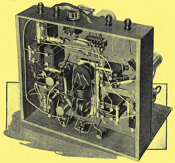
The low-pass filter can be seen in the centre of the chassis, above its controlling switch.
The maximum volume obtainable on both radio and gramophone is sufficient for all normal requirements, and for ordinary domestic use, where the volume control will be somewhat retarded, there should be a complete absence of overloading effects on even the loudest passages. On, gramophone, it should be noted, the low-pass filter can still be used if desired, and here it will serve to remove all traces of needle scratch.
The purpose of the switch S1 and the resistance R9 have yet to be explained. The normal condition of the receiver is with this switch closed, and the sensitivity is then at its maximum. As a result, the process of tuning is apt to be rather noisy; the maximum sensitivity of the set is exceptionally high, and with the switch closed is always present when the set is not tuned to a station. Atmospherics and local interference, therefore, present an annoyingly strong background. As the set is tuned into a station the sensitivity decreases, but it is still abnormally high until exact resonance is obtained. While tuned to the sidebands, therefore, distorted reproduction is found. For correct results it is essential that the tuning be really accurate, and it is a help, therefore, if the meter at X be left permanently in circuit to serve as a tuning indicator; it is by no means essential, however, for it is quite easy to arrive at the correct condition by ear.
It will be evident, therefore, that during the process of tuning a reduction in the maximum sensitivity is desirable. This is achieved through the use of R9. With the switch S1 open, R9 should be adjusted so that the background found with the set not tuned to a station is as loud as can be comfortably tolerated. During tuning, therefore, the switch is kept open, and nothing louder than the predetermined level will be found. When a station is tuned in, the switch can be closed; if the station is strong there will be no change in apparent volume owing to the AVC system, but there will be a change in the meter reading. If the station is weak, of course, volume will increase. Although there will be no change of volume on closing the switch with a strong signal, it is advisable to do so in case the station starts fading, for if the switch be left open AVC may fail to compensate fully for fading. The second use of the switch is for local reception. The AVC system will hold the output constant provided the input to the HF valve does not exceed about 1 Volt; when the set is used with a good aerial close to a local station, however, some 5 Volts or more may be found on the first valve, and the valves may become overloaded. It is usually the IF stage which overloads and makes it impossible for the AVC system to provide sufficient bias voltage. Should it be found, therefore, that reproduction from the local station is distorted with the switch S1 closed, it should be opened and R9 should be adjusted to such a value that good quality is secured. This point will usually be just short of that at which it begins to have an effect upon the volume.
Every station which is separated from its neighbours by 9 kHz or more should be receivable without interference, and if use be made of the switch S3 even stations separated by 5 kHz can be made to give enjoyable results. The dial settings are bound to vary somewhat with different sets owing to variations in the components, so that little purpose would be served by giving a list of dial settings. In general, however, they will be similar to those of the original Monodial AC Super and the list given for this may be taken as a rough guide. The tuning range has been measured, and was found to be 1,500-525 kHz and 395-145 kHz, corresponding to 200-570 Metres and 760-2,060 Metres.
Mounting the Receiver
The question of cabinets for this receiver has been left to the choice of the constructor, since this is a matter in which personal preference counts for more than technical merit. It may be mentioned, however, that suitable types are obtainable from a number of firms, including Peto-Scott Co, Ltd, and The City Accumulator Co., Ltd. Also full kits of parts are being advertised in this journal.
If the cabinet selected be arranged to include both set and speaker it is wise to mount the receiver chassis upon rubber cushions, otherwise acoustic reaction from the speaker may cause a low-frequency resonance, or even a sustained howl. An absorbent mounting is easy to arrange by resting the receiver chassis on blocks of sponge rubber so that it can float freely. A gap must, of course, be left between the panel and the cabinet, and this may well be filled with rubber to exclude dust. The precise method of mounting must obviously vary in different cases, but it is usually easy to arrange an absorbent support which is fully effective in eliminating the effects of feed-back.
The choice of a loud speaker is a matter of some importance, but one which is too lengthy to enter into here. It is hoped to deal with this matter in a further article, therefore, and in the meantime it is sufficient to stress the importance of securing a type capable of giving a uniform and wide frequency response, and also able to handle an input of some 6 Watts without causing harmonic distortion. A point often overlooked, but not without importance, is the power rating of the output transformer, and here again this must be for 6 Watts. In connection with the table of voltages, it should be mentioned that the columns headed Anode Volts refer to the voltage measured between the chassis and the anode terminal of the valve in question. The bias voltage is measured between chassis and cathode, so that the reading obtained for anode voltage is really the sum of the true anode and the bias voltages. This accounts for the figure of 270 Volts for the PX4 valve. The actual anode voltage, of course, is 270-38 = 232 Volts, which is well within the maker's rating.
It should be noted that the control knobs supplied with the various components do not all match. For the sake of a neat finish, therefore, it may be considered advisable to obtain uniform knobs for the volume and range change controls. These used in the original receiver were the Bulgin types K13 and K14.

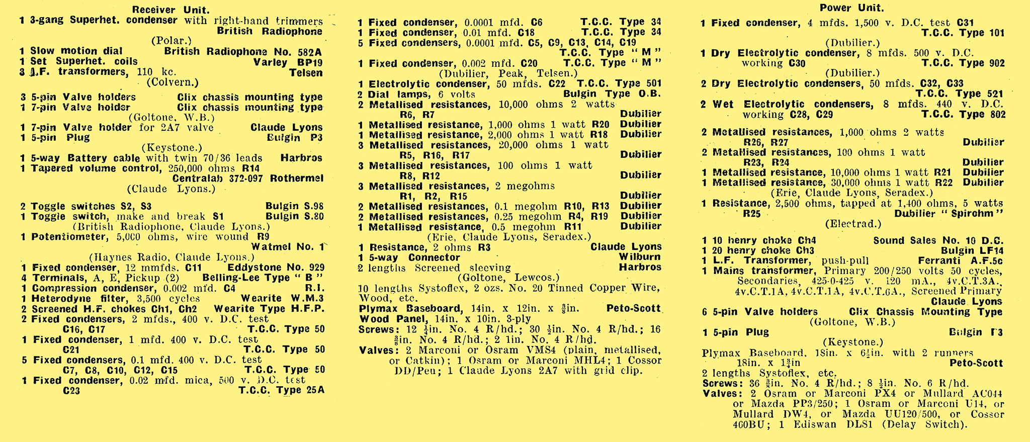
Components list.
|