|
Circuit Details: 4, 8 and 12 Watt Designs.
In 1934 there appeared in Wireless World a design for a high-quality amplifier having an output of 4 Watts. It was a double-push-pull resistance-coupled amplifier designed for quality of reproduction first and foremost, and because of its outstanding performance in this respect it proved exceedingly popular. Since that time various modified amplifiers have been described and the modifications have taken two forms; on the one hand they have been made to obtain increased output and on the other to simplify the amplifier.
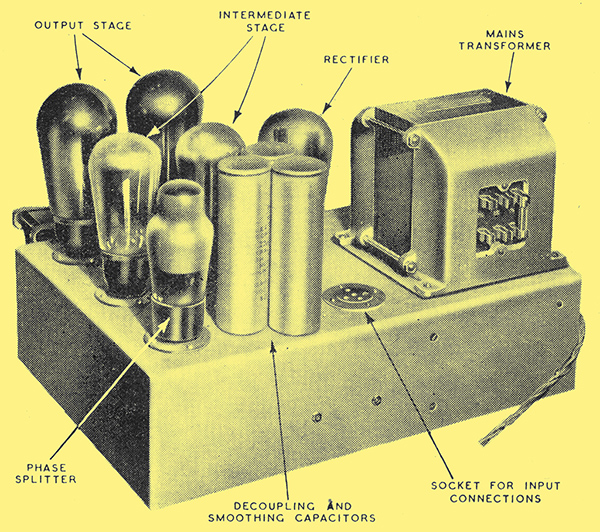
A typical amplifier layout. Notice that the electrolytic capacitors are mounted well away from the really hot valves.
The first category of changes resulted chiefly in alterations to the mains equipment and output valves. A change in the makers rating of the PX4 valve, for instance, permitted increased output to be secured by increasing the voltage, while by substituting PX25 type valves and further increasing the voltage still greater output could be secured. The second type of modification lay in simplifying the circuit as knowledge of the properties of push-pull amplifiers increased. The original design had separate bias resistors for each valve, and these needed individual by-pass capacitors of large capacitance. It was later found possible to use a common resistor for each push-pull pair of valves and to dispense also with a by-pass capacitor. This entails no sacrifice of importance, but rather an improvement, for the common resistor tends to correct for variations between valves.
The present position is that there is a number of designs for amplifiers scattered through Wireless World and dating back to 1934. The designs vary in output and they progressively become simpler in detail, but they all bear a strong family likeness and it is easy to trace their development from the original.
On looking through these designs one is immediately struck by the fact that there are three basic designs differing only in output, for the simplifications to the original amplifier apply whatever the output. It becomes possible, in fact, to draw a common circuit diagram for all three.
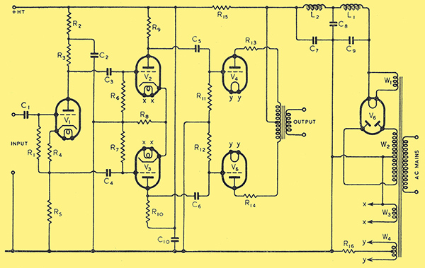
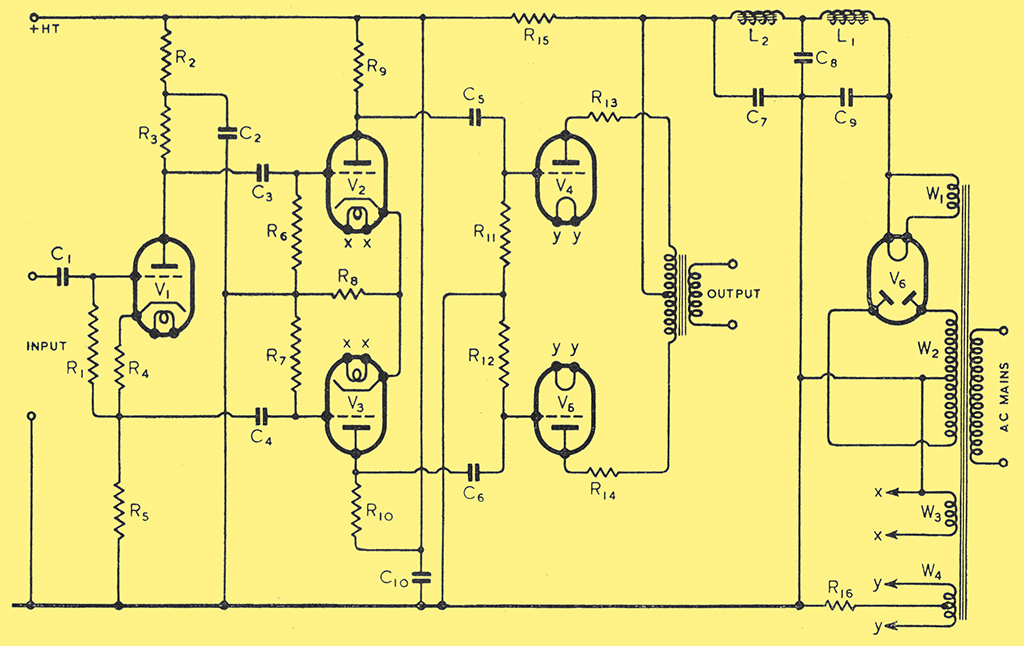
Fig. 1. This diagram shows the amplifier circuit and mains equipment for all three output powers. R15 and C10 are needed only for the 12-Watt version.
This diagram is shown in Fig. 1, and it will be seen that the amplifier consists of an input phase-splitter V1, a resistance-coupled push-pull stage V2, V3 and an output stage V4, V5. There are many other possible phase-splitting arrangements, but the one shown here has been found very satisfactory over a period of many years, and it is very doubtful if there is a better for this purpose. The stage is, in essence, a cathode follower, but having a resistance R3 in the anode circuit which is equal in value to the cathode resistance R5. The alternating anode current flows through both, and as they are equal in value, the alternating voltages at anode and cathode are equal in magnitude but opposite in phase with respect to earth.
Grid bias is provided by R4 and the grid leak R1 is returned to the negative side of it. There is one point to watch here. There is heavy negative feed-back from the resistance R5, with the result that the input impedance of the stage is very high. Because of this, the grid of V1 is more liable to pick mp hum from stray electric fields than usual, and it is wise to keep the grid connections very short. With any reasonable layout screening should be unnecessary, but if hum is found V1, C1 and R1 should all be screened.
Decoupling is provided by R2 and C2 and smaller values than those specified are inadvisable. These values should, however, be in all cases adequate. C3 R6 and C4 R7 provide the coupling to the first push-pull stage. It is important for the capacitors to have high insulation resistance, since if they are at all leaky the operation of V2 and V3 will be upset. A leak at this point will do no material damage, however, but in the coupling to the output stage a leak in C5 or C6 may damage V4 or V5, so that it is particularly important to make sure that these capacitors have good insulation.
If a proper measurement of insulation resistance cannot be made, a. somewhat crude test usually gives a satisfactory indication of the state of the capacitor. This is to connect it in series with a 1,000 Ω-per-volt. voltmeter to a 200 Volt or higher supply. On making the connection the meter needle will flick upwards slightly because of the charging current, but on subsequent breaking and remaking the circuit there should be no trace of flicker. A current of only a few micro-amperes is sufficient to cause a perceptible flicker, so that the absence of such flicker is an indication that the insulation resistance is at least several hundred megohms.
Another method, which is simple to apply to capacitors in the complete amplifier, is to check the anode current of the following valve, with the grid leak short-circuited and normal. Thus, if it is desired to check C5, insert a meter in the anode circuit of V4 and note the current. Short-circuit R11 and again note the current. If all is in order the two readings should be the same, but if C5 is leaky, the second reading will be lower than the first.
The first push-pull stage comprises V2 and V3, with the coupling resistors R9 and R10. A common bias resistor R8 is used and has the effect of providing a self-balancing action to the stage which partially compensates for differences between the two valves. It does, however, tend to accentuate differences between R9 and R10, and these two components should be chosen to be as nearly alike as possible. The usual 20% tolerance is quite good enough on their absolute value, but they should be alike within much closer limits and some 2% is ideal. By checking over a few resistors one can usually pick two sufficiently alike. These remarks also apply to R3 and R5, since their values control the input to the push-pull amplifier.
The output stage has a pair of push-pull triodes, again with a common bias resistor R16 and anti-parasitic oscillation resistors R13 and R14 are included. It is an additional help to arrange the layout so that the grid leads of V4 and V5 and the anode leads of V2 and V3 are very short. The mains equipment consists of the usual full-wave rectifier V6 and a two-stage smoothing circuit, and is quite conventional. R15 and C10 are needed only when PX25 output valves are used and R15 then drops the voltage to the early valves.
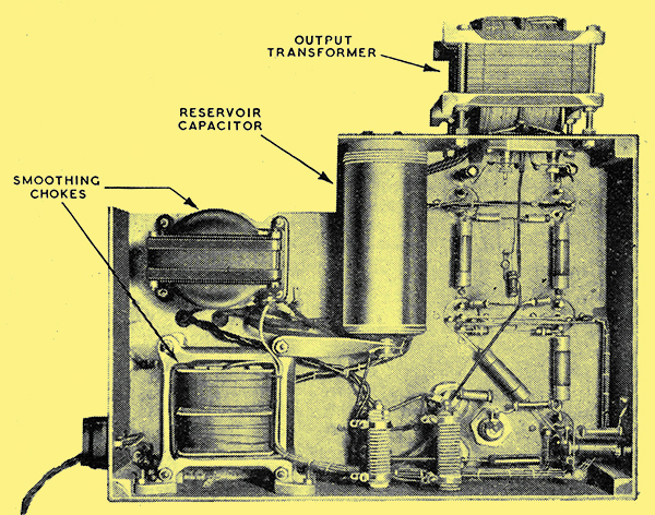
An under-side view of the amplifier. The cut-out in one corner of the chassis is merely to clear the speaker pot, for space is restricted in the cabinet used for this amplifier.
So far the amplifier has been discussed on the general circuit which is common to all three outputs and it is now necessary to consider individually the points of difference. It may be remarked at this point, however, that in the mains equipment allowance has been made for a current of 20 mA to be available for any preceding feeder or input unit.
For an output of 4 Watts, PX4 valves are used for V4 and V5 and are slightly under-run. In this condition they can be relied upon to give an exceptionally long life. They are operated with 250 Volts between anode and cathode and 35 Volts grid bias. Allowing for a small drop in the output transformer; the HT supply needed is 295 Volts, and the current is 70 mA, 35 mA per valve. An anode-to-anode load of 10,000 Ω is then required.
The penultimate stage takes some 8.4 mA and V1 needs about 1.2 mA, so that the amplifier as a whole needs just on 80 mA. Allowing 20 mA for any preceding unit, the mains equipment is designed for an output of 100 mA at 300 Volts in round figures. A total resistance of 500 Ω is allowed for the two chokes, making the rectifier output 350 Volts at 100 mA. This is obtainable with a valve such as the U14 for V6 with a transformer winding of about 325 - 0 - 325 Volts.
For an 8 Watt output the same valves are used in the output stage and the bias resistor is unchanged. The valves now work with 300 Volts anode-to-cathode and need some 45 Volts grid bias. Under these conditions they take 50 mA apiece, and the total HT supply becomes 350 Volts at 130 mA. The drop in the chokes becomes 65 Volts, so that the rectifier output needed is some 415 Volts.
The current of 130 mA is rather beyond the rating of the U14, so that the U18 should be used. Of course, if the preceding stages do not take more than 10 mA the total current becomes only 120 mA and a U14 is still permissible.
The output stage needs a load of 6,400 Ω under these conditions and it requires 45 Volts peak input per valve instead of 35 Volts. The penultimate stage is now fed from a 350 Volt line instead of a 300 Volt, so that its output is automatically increased. The amplifier as a whole needs 28% more signal input for the 8 Watt output than for the 4 Watt.
It will be seen that the only changes between the 4 and the 8 Watt amplifiers are in the voltage ratings of C8 and C9, the load resistance of the output stage, the rectifier valve V6, and the mains transformer.
In the case of the 12 Watt amplifier, the main change is in the use of PX25 output valves. These need 400 Volts anode-to-cathode with 31 Volts grid bias and take 62.5 mA apiece. The HT supply then jumps to 450 Volts at 155 mA. R15 is introduced to drop the voltage to 300 for the early stages and a by-pass capacitor C10 becomes necessary. The un-smoothed voltage needed becomes 530 and a U18 rectifier is again suitable. There is now a considerable increase in the capacitor voltage ratings needed and together with the higher voltage mains transformer the power supply becomes more expensive. The output stage needs a 6,000 Ω load.
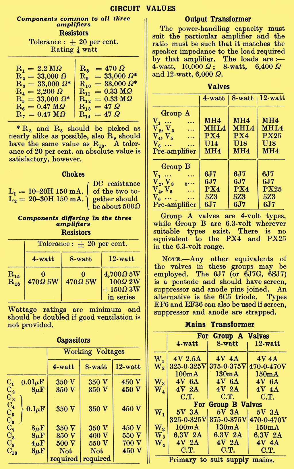
Precise details of the values and ratings of components are given elsewhere, but it may be remarked that the voltage ratings given for capacitors are minimum working ones. They are safe ratings for new good-quality components, but if only old stock is available it is a good plan to pick capacitors of higher rating.
The resistor wattage ratings specified are adequate, provided that the ventilation is good. If it is not, the rating should be at least doubled in the case of the higher-wattage resistors. Even then it is bad practice to use poor ventilation, for it means that the heat generated in resistors and valves raises the temperature of the whole equipment and this is likely to be harmful to the life of the capacitors.
If the usual form of chassis construction is adopted, it is a good plan to keep the hot parts above the chassis and the cool ones below. Mount all resistors of over 1 Watt rating above the chassis and keep all capacitors away from hot parts.
It will be noticed that the ratings given for capacitors are somewhat higher in the case of the 12 Watt amplifier than for the others, in spite of the fact that the working voltages are the same. The reason for this is that higher voltages exist when the equipment is switched on and before the indirectly heated valves start to draw current, and the capacitors must withstand this voltage.
In both the 4 Watt and 12 Watt amplifiers the HT voltage for all valves except the output is nominally 300 Volts, but in the 8 Watt amplifier it is 350 Volts. By including R15 in this last amplifier the voltage could, of course, have been reduced to 300 Volts as in the others. This was felt to be undesirable, however, because the output valves need a bigger signal input in this amplifier than in the others and a somewhat higher anode voltage on the preceding stage is consequently desirable. The point should be borne in mind, however, when working out dropping resistor values for any early valves.
The signal input needed by V1 is approximately 2.5 Volts RMS for full output. It is slightly less with the 12 Watt amplifier and a. little more with the 8 Watt. It can be fed directly from the detector of a receiver, therefore, but an extra stage will usually be necessary for a gramophone pick-up. This stage must provide the amplification necessary to bring the pick-up output up to the 2.5 Volts needed by the amplifier, and it should also have a characteristic rising at low frequencies to correct for the normal loss in the recording.
The amplification required is not high, for there are but few pick-ups giving a smaller output than 0.25 Volt and some give well over 1.0 Volt. An amplification of some 5-10 times, to suit pick-ups giving from 0.25 - 0.5 Volt output, will therefore meet most needs.
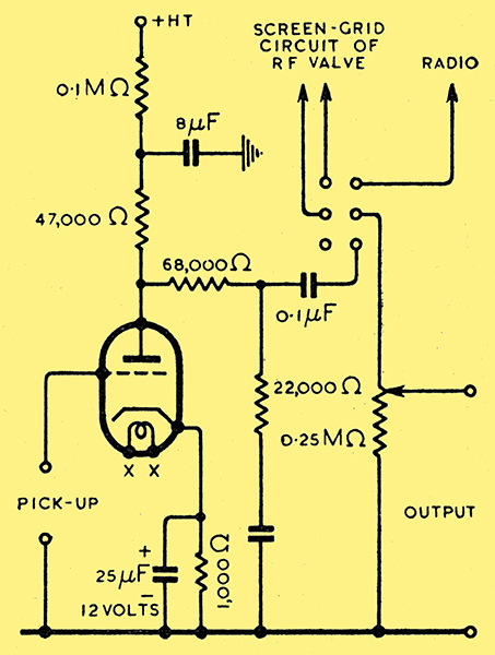
Fig. 2. A pre-amplifier to correct for recording deficiencies is usually necessary. The resistors can all be of 0.25 Watt rating except for the 100 kΩ, which should be 0.5 Watt. The capacitors should be of 350 Volt rating for the 4 and 8 Watt amplifiers and of 450 Volts for the 12 Watt. The bass lift capacitor in series with the 22 kΩ resistor is 0.05 μF
A suitable pre-amplifier and corrector is shown in Fig. 2, and with a valve of the MH4 type the amplification is about 6.5 times. This is sufficient for most pick-ups and caters for types having outputs exceeding 0.4 Volt. The gain control is placed after this valve so that it can function on both radio and gramophone. This makes it necessary to be careful to avoid overloading in this corrector stage. There is little fear of this with the magnetic type of pick-up, but it is not unlikely with the piezo-electric crystal kind, which has a large output. If this effect is found the pick-up should be shunted by a fixed potentiometer so that only part of its output is applied to the valve. The pair of contacts on the 'radio - gram' switch labelled 'Screen-grid circuit of RF valve' should be wired in series with the screen-grid connection of one or more of the RF stages, so that the screen voltage is removed on gramophone to prevent the break-through of radio signals. The connection should be made at a point of low RF potential.
Component List
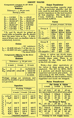
In the above list R9 and R10 should be half Watt types.
|