|
A simple explanation of a fascinating subject.
Probably the first high-definition set sold in the UK.
Contents
Television articles index.
The idea of television has always been an attractive one, both to the visionary dreamer and to the practical technical man who sees a problem to be solved. At the moment the interest in the subject is greater than it has ever been, following on the recommendations of the Postmaster-General's Committee for the early inauguration of a broadcast service of high-definition television.
Numerous textbooks on the subject already exist, but many of them are now too historical to be of much current value. Some are too diffuse in regard to particular 'systems' to give a broad enough picture of the whole subject; others are too specialistic in detail for the more general reader. There is no-published explanation of the subject which is up-to-date in presenting to its readers the position as it stands at this moment following on the Report of the Committee appointed by the Postmaster-General.
A booklet of this size cannot hope to cover the scope of a large textbook, but in it an attempt is made to explain the principles of television in a simple manner. Some degree of electrical knowledge is necessary to understand it thoroughly; but the elementary principles of electrical communication are explained in sufficient outline, we hope, to render the subject broadly comprehensible to the reader whose technical knowledge is slight. In particular, it is hoped that it may be found suitable for reading by members of the family generally, as well as the 'wireless expert', and that it may stimulate the general interest.of the home circle in a new technique which, even though its development may be slow, promises vistas that have often been dreamed of but are only now approaching realisation.
It will not be out of place, in this introduction, to draw attention to the fact that some very erroneous ideas are current regarding television, both in relation to what it is capable of accomplishing and its immediate importance as a new form of entertainment.
Although television is one of the most spectacular scientific achievements of our generation, we must not be led to suppose that it is in anything like a highly developed state at present. Progress will undoubtedly be made, but it is not, and perhaps never will be, a substitute for our present broadcasting. It seems more than likely that, although it is to be sponsored by the BBC, it will always be conducted as a separate enterprise, on the transmitting side, including the programme material, and the very fact that quite different wavelengths have to be utilised implies the use of receivers quite independent of those normally used for broadcast reception.
As great a problem as that of technical development is the choice of programme material. It will not be easy, even for the proposed programmes of an hour or two a day, to find matter which will retain the interest of the public as an entertainment. We must not forget that when the wonder of television has passed, critics will soon begin to compare its value as an entertainment with the cinema - a very unfair comparison, of course, but one which, nevertheless, is bound to be made.
These remarks may seem to some to be discouraging to the new art, but surely it is better that the public should face television with some understanding of its limitations, rather than that they should be carried away with enthusiasm and meet with some disappointment when their expectations are not entirely fulfilled.
Simple Telegraph and Telephone Circuits
All forms of electrical communications can be said to consist of means of producing electrical impulses at the sending end of a communicating system and using what is now generally called a 'channel' of communication to convey these impulses by some electrical means, wire or wireless, to our receiving end. Here they cause some instrument or suitable device to reproduce the impulses sent out by the transmitter. Of all the means that we now use for the electrical conveyance of intelligence none represents greater complexity than television, touching, as it does, on so many different branches of science and engineering and governed by factors in which the human senses are not the least important. In order, therefore, to present a logical account of the subject it is necessary to trace it from the very simplest form of electrical communication and to develop it to embrace the principles which we are likely to see in use in practical television of the very immediate future.
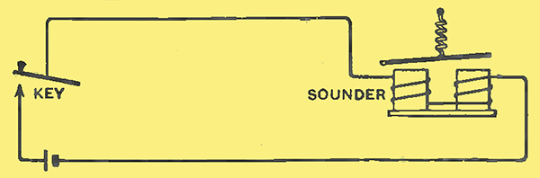
Fig. 1. - Elementary telegraph circuit.
The simplest form of electrical communication that we can imagine is the elementary wire telegraph circuit illustrated in Fig. 1. When the sending key is depressed current flows from the battery round the whole circuit. At the receiving end it passes through the windings of an electromagnet and causes it to attract its hinged armature of soft iron which is normally held away by a spring. If the key is moved up and down to form the dots and dashes of the Morse code, the hinged armature moves in accordance with it, and the clicks which it can be caused to make are intelligible to the expert listener. Modern telegraph methods have, of course, moved far from this embryonic system of nearly a hundred years ago, but it still serves the best possible introduction to any other method of electrical communication.
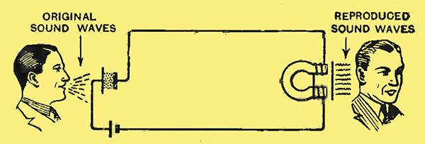
Fig. 2. - Simple one-way telephone circuit.
When we wish to convey sound we again arrange, in a somewhat similar manner, that the sound should actuate some device at our sending end, so that an electrically operated device at our receiving end may move in sympathy. It is now very generally known that sound is due to something being made or allowed to vibrate, and that these vibrations set up waves in the air. In the case of direct hearing, these air waves cause sympathetic vibrations of the ear-drum, which are finally appreciated by the brain (or part of it) as the familiar sensation of sound. In hearing electrically by the telephone, on the other hand, we first use the air waves from our source of sound to produce our electrical impulses. This is done, in the simplest case, as illustrated in Fig. 2. Before we speak into the microphone there is a steady current in the circuit. When we speak, the sound waves cause the front diaphragm of the microphone to vibrate and thereby to vary the pressure on the loosely packed granules of carbon that lie between the front diaphragm and the back of the instrument. This causes the electrical resistance of the microphone to vary so that the current round the circuit is no longer steady but is also caused to vary sympathetically. At the receiver these varying currents again pass through an electromagnet (in the well-known telephone earpiece) and it, in turn, vibrates a soft iron diaphragm which thus reproduces air waves, which our ears can hear, similar to those at the speaking end, although of feebler strength.
Sound and Pitch
Before proceeding further it is well to step aside at this point and introduce a term which will be met a great deal in our further discussion. This is the word 'frequency'. Reference has been made above to the fact that sound is due to vibrations, and we know that the pitch of the note we hear is governed by the rate or number of vibrations per second. This is called the frequency. When we strike the familiar 'middle C' of the piano the string vibrates 256 times per second, the C above this 512 times, the C below 128 times per second. The top note of the piano represents nearly 4,000 vibrations per second, the lowest note about 30. Other sounds have still higher frequencies than the 4,000 quoted above, and, as a result of many measurements made within the past few years, we now know that frequencies up to 15 or 16 thousand vibrations per second are involved in some of the items that go to make up the background of sound and noise which is with us all our waking hours. High as these frequencies may appear, they are ridiculously low compared with some of the frequencies with which we will be concerned later.
And here, too, it is well to emphasise another important point that must be mentioned in our later discussions. If any part of our system refuses to respond to all the range of frequency which it is liable to encounter in the course of its work, our reproduction immediately suffers in the somewhat undefinable quality described as naturalness. A simple comparison is that of an ear which fails to respond to the higher notes, thus causing its owner to live in a permanent world of quite unnatural sounds. Early broadcast receivers and loud speakers also afford such a ready example that this matter need not be further elaborated.
Complicated as these processes may appear, it is also well to realise their simplicity relative to those of vision and television. We all know that several sounds can exist and can be detected at once, but the pressure exerted on our ear-drums at any instant is only a single air wave made up of the addition of all those occurring. The ability to distinguish the different sounds is a function of the brain.
The Wireless Link
In considering the wireless equivalent to the simple telephone circuit of Fig. 2, we have to recall that when the microphone is inoperative the aerial is 'oscillating' (as we now call it) at a very much higher frequency than any we have so far considered, for example, running into hundreds of thousands or into millions of oscillations per second. Such frequencies are much above those to which the ear responds at all, but our wireless aerials respond to them, and we get the maximum response by the familiar process of tuning our receiver. For example, if our wavelength is 300 metres, then electrical energy in our aerial is steadily oscillating at the frequency of one million cycles per second. If we are using a shorter wavelength the frequency of our oscillations is still higher, so that the 20-metre wavelength, used to span the Atlantic for some of the transatlantic commercial telephony, represents frequencies of 15 million or 15 megacycles [★] Vibrations or oscillations are usually expressed in Hertz (Hz) (previously cycles per second), and kilohertz (thousands) and megahertz (millions) are used for higher values, e.g., 1,000 cycles (Hz) = 1 kilocycle, 1,000,000 cycles = 1 megacycle.. With the shorter waves now envisaged for our new television service, a 6-metre wavelength represents oscillations of 50 MHz frequency.
Thus, in the wireless equivalent of the simple telephone of Fig. 2, during periods when the microphone is not actuated the aerial is steadily oscillating at a high frequency much beyond the response of the ear. The aerial is then sending out ether waves of constant amplitude or strength, known usually as the carrier wave. If, now, sound falls upon the microphone this carrier is no longer of steady strength, but rises and falls in amplitude, in sympathy with the sound. This process is usually described as modulation indeed,. the same term is applied to the process of varying an otherwise steady current, as discussed in connection with Fig. 2. or of producing desired variations in any sort of effect.
When our receiving aerial is tuned to the radio frequency carrier, currents are set up in it exactly similar in character to those at the transmitting aerial, but, of course, of a greatly reduced strength. By processes which are familiar to technical readers of this booklet and need not be elaborated here, we employ valves to amplify these currents, then by the process known as detection (or rectification or demodulation) we extract. as it were, the variations in strength which represent the fluctuations caused by the sound. These current variations-usually further amplified by our audio frequency or 'low frequency' valves - are finally applied to,the loud speaker, causing its diaphragm to vibrate sympathetically in a manner generally similar to that already considered in the case of the simple telephone circuit of Fig. 2.
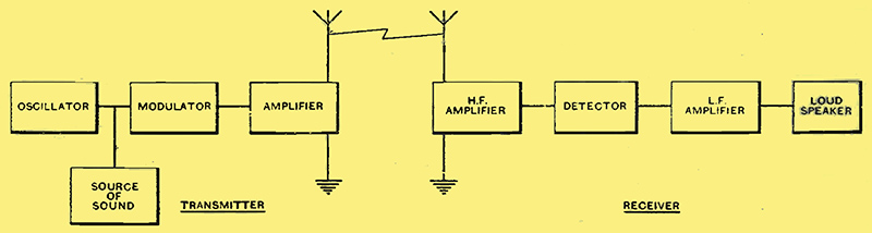
Fig. 3. - Schematic arrangement of wireless link (equivalent to simple telephone circuit of Fig. 2.
From these simple considerations we are able to compile the schematic diagram of Fig. 3 as representing the essentials of our system of wireless communication. At the transmitter, an oscillator generates an electrical current of high frequency, say 1 MHz. This passes to the modulator where it meets the low frequency or telephonic effect arriving from what is described generically as a 'source of sound'. The high frequency is there modulated in the manner described above, and the whole is amplified in scale before going on to the aerial. At the receiver the process is as stated in the last paragraph and is one already familiar to most of the readers of this booklet.
The Importance of Variations
In all the simple cases considered above it will be seen that a steady state of things conveys no message. For example, in the simple telegraph circuit of Fig. 1 so long as the key is kept stationary in either its up or down position we are conveying no intelligence; it is the movements up and down - the variations - that are responsible for our communication. In the telephone of Fig. 2 the steady current round the circuit conveys no message; it is the variations of this current, due to speech into the microphone, that convey our message.
Similarly with the wireless telephone, the sustained oscillations of the carrier convey no intelligence and are, indeed, quite inaudible to the ear. It is only from the variations under the influence of sound that we obtain our message.
Yet one other fundamental thing must be considered in our wireless link before we come to our main theme, and this, as we shall later see, is a particularly important one in relation to the difficulties of television. This is a secondary effect which is produced when we modulate a wireless carrier wave for the purpose of telephony or, for that matter, for the purpose of television.
When we modulate the carrier in the manner described, the variations of amplitude have the remarkable effect of causing a great spread of frequency. The simplest way to express it is by a definite case, where we assume that the carrier has a frequency of one million. If we modulate this by a note of, say, 1,000 frequency, the effect is that while our aerial still oscillates at the rate of one million, new frequencies are also set up which are respectively one thousand below and one thousand above the carrier. That is to say, the oscillations in our aerial now comprise three frequencies, 999,000, 1,000,000 and 1,001,000. The proof of this is difficult, but has been given in technical articles in The Wireless World (of October 5, 1934). In any case, the facts are well known and established, and are simply equivalent to saying that we spread into the ether on each side of the carrier by the amount of the frequencies contained in our modulation.
It has already been stated that in telephony we may have frequencies up to 15 or 16 kHz, but in the present state of the broadcasting wavelength allocations we are not able to use such a spread without great interference between stations. Assuming, therefore, that our modulation may contain a maximum frequency of 10 kHz we see that when sound is being transmitted a spread of frequency up to 10 kHz on each side of the carrier is liable to occur at any instant.
The importance of these facts relates both to the position of our carrier as regards frequency, and also to our transmitting and receiving apparatus. As regards the first, with a crowded ether we obviously cannot allow one station to create a very wide spread of frequency which will carry it into the region occupied by another station. As regards the second, it will be clear that, for fidelity of response, our apparatus must be capable of handling as wide a band of frequencies as is necessary for the particular type of communication that we wish to effect. For example, if the transmitter makes a spread of 10 kHz on each side of the carrier, and our receiver is very sharply tuned so that it only responds to 2 kHz, then we lose all the range of modulating frequencies above this value, and the quality of our reproduction suffers accordingly. The effect can be compared to that of driving a wide coach through a narrow arch. Either the vehicle must be made narrower to fit the archway, or the arch must be widened to take the coach.
A Hypothetical Television System
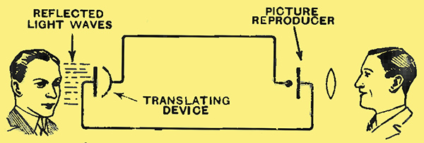
Fig. 4. - A hypothetical television system.
From what has been said it will be realised. that theb essentials of a hypothetical system of television communication can be as illustrated in Fig. 4. Let us assume that the head at the left side of the diagram is flooded with light, some of which is reflected on to the 'translating device'.This device must, at the moment, be admitted as purely hypothetical, but we will imagine that it succeeds in translating the light into corresponding electrical impulses. These, as before, are transmitted over the line, where they actuate a 'picture-reproducer', which is also frankly hypothetical, but succeeds in reproducing an image of the scene at the distant end.
Unfortunately, the facts are not so simple as those of our hypothetical illustration. This is due to the much more complicated nature of sight as compared with hearing. In vision we do not deal with a single set of conditions as has been shown-to exist with sound. Instead, the eye receives a separate and definite impression from every point within its field of view. This is best illustrated by considering the action of the human eye and its associated nerve system.
The eye is, in effect, a form of the familiar camera. It has a lens and a screen, and the lens forms upon the screen known as the retina - an image of the scene within the field of vision. The focusing arrangements are, of course, more marvellous than those of our best manufactured lenses, but that part of the process is very similar to the familiar one of forming a picture on the ground-glass screen of a camera. The image on our retinal screen is then used to convey a message to the brain, which is, as before, the real seat of the senses. The retina consists of an extremely fine mosaic made up of an enormous number of tiny cells, each directly connected with the brain by a nerve system. These communicate impulses to the brain according to the manner in which they are stimulated by the image focused on the retina. It is important to realise, however, that the process is not a simple addition of several effects into one combined effect (as in sound), but is the separate appreciation of a vast number of individual impressions all existing together and enabling us to discriminate colour, intensity of light, direction, etc. If we attempt to analyse into their separate elements all the constituents of a scene which the eye perceives as a comprehensive whole, we find it comprises perhaps a hundred million elements.
Early Conceptions of Television
Thus we see that for television we should almost require our hypothetical 'translating device' of Fig. 4 to consist of a structure like the retina of the eye itself, comprising millions of minute translating elements, each connected by a communication channel of its own to a similar reproducing element in our hypothetical 'picture reproducer'. This is, of course, fantastic. Nevertheless it was, in effect, the first suggestion for television. So long ago as 1875 it was proposed to imitate the human eye by a mosaic consisting of a large number of minute selenium [★] Selenium is a material sensitive to light and capable of changing its resistance to an an electrical current in proportion to the intensity of the light falling on it. cells. These were each to be connected to an electromagnet device opening a shutter which normally covered a spot of light. An image of a picture focused on the mosaic of selenium cells would then expose a corresponding pattern of light at the distant end. A coarse checker-board mosaic of this type, consisting of 64 selenium cells, was actually tried tentatively and used to transmit images of simple letters and figures.
The obvious impracticability of such a system, however, either for wire or radio, rules it out for any purpose other than a visionary attempt to simulate the physiology of the eye.
In the concrete case, therefore, of reverting to our system of Fig. 4, we would find that if we took a practicable translating device, such as the familiar photo-electric cell, the electrical response would simply be proportional to the total illumination from the object reaching the cell. That is, it would be a single effect, and we are faced with the stern necessity of converting this into a number of separate effects, presented so rapidly one after the other that the eye is deceived or persuaded into believing that they all exist at once.
The Need for Scanning
This is fulfilled by the process of scanning, which consists of transmitting the picture point by point. It then becomes possible to transmit the image over a single communication channel and use a point-by-point method to reconstruct it at the receiving end.
Pursuing this idea, let us suppose that we are transmitting a picture and have agreed (as above) that we cannot do it in a single operation. If, then, we break up the picture into different pieces and let the light reflected from each piece fall on the photo-electric cell in very rapid succession, we should find that the electrical response of the cell from instant to instant would vary according to the light and shade of the different parts in the order in which they were examined. Pursuing the idea still further, if we break up the picture into an infinite number of elements and let the light from each element fall in rapid succession on the cell we shall obtain electrical variations of current which represent a complete copy of every detail of the picture in the order or sequence in which we examined the elements. These impulses have then to be transmitted over the communication channel in their appropriate sequence, and converted at the receiving end into corresponding variations of light. In order to reconstruct the picture it will be seen that these light impulses of varying strength have to be presented to the eye (a) in very rapid succession, (b) in their proper sequence, and (c) in their appropriate relative positions to each other.
The Half-tone Analogy
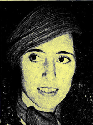 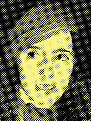 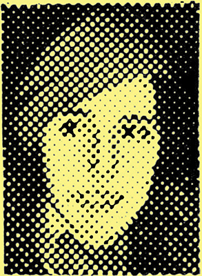
Fig. 5. - In making this picture a block with a normal screen has been used.
Fig. 6. - In this picture a coarse screen has been employed with the result that much of the detail has been lost.
Fig. 7. - Here the screen is so coarse that little resemblance to the original picture can be seen at first, but if examined from some distance the definition apparently improves.
The idea of breaking up a picture into a large number of very minute elements or-points is not a new or radical one. Even as regards television it is interesting to recall that Nipkow, as long ago as 1884, suggested the scanning disc as a means of breaking up a view or picture for electrical transmission. The principle of breaking up in this manner is also already a familiar one in printing 'half-tone' blocks. Any printed half-tone illustration, if examined under a sufficiently powerful magnifying glass or microscope, will be seen to consist of a large number of minute dots, corresponding to what is known as a 'screen'. The greater the number of dots to the inch the better is the quality and detail of the picture. This is illustrated by the successive pictures in Figs. 5, 6 and 7. In Fig. 5 a screen has been used normal to this type of printing, e.g., about 85 dots to the inch, and the picture is of a quality to which readers are accustomed. In Fig. 6 the screen is of about 22 dots to the inch, and the loss of detail is very marked. Fig. 7 consists of half this number of dots per inch and is an example oi the loss of detail with such coarseness, when examined at a normal reading distance. Incidentally, if the pictures are looked at from a greater distance the differences appear much less, and the worst picture, if not satisfying, becomes at least intelligible.
The process of point-by-point structure also exists with ordinary photographs except that the points are extremely small. For that matter, as has been shown, it still exists with the eye itself, except that the points are so infinitesimally small that we are unconscious of the process.
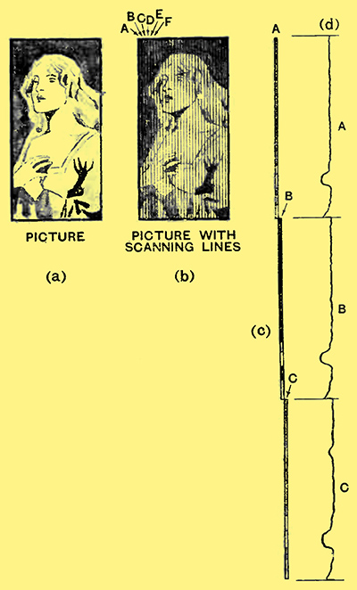
Fig. 8. - The picture to be transmitted is shown at (a), and at (b) the effect of scanning can be seen. The strip A is first scanned and then B, so that in regard to time the picture is broken up into a long strip (c) and the photocell current varies as shown at (d).
The dot analogy is perhaps not strictly accurate in television, where the picture is normally broken up into a series of lines rather than distinct dots. The underlying principle, however, is the same, and the resemblance is strengthened by the fact that each line may vary in brightness from point to point in its length, thus approximating very closely to the idea of dots. The principle of breaking up a picture into a series of strips is shown in Fig. 8, where (a) shows our picture in its normal appearance, and (b) shows what its appearance would be if we divided it off into 30 vertical strips, A, B, C, etc. Suppose further that instead of keeping these strips parallel and side by side, as in Fig. 8 (b), we placed them, while still parallel, end to end as in (c) of the diagram. This gives a clear impression of the sequence of changes of light and shade which our scanning element would encounter as it moved downwards first over strip A, then over strip B, then over strip C, etc. And finally, suppose that we have some form of device sensitive in its response to light and shade and giving us, in fact, electrical current impulses according to the degree of light which it encounters. As the scanning element moves along the strips, A, B, C, etc., in turn, the current in this device will vary as shown in Fig. 8 (d). From what has already been said it will be clear that these current variations can now be used to modulate a communication channel, in exactly the manner we have previously considered.
The Photo-electric Cell
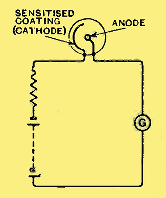
Fig. 9. - Principle of the photo-electric cell.
Fortunately, a device of the kind envisaged above is actually available. It is known as the phot0-electric cell, and, as we shall see, it represents one of the most essential features of all the methods of television that we shall consider in these pages.
In its essentials the photo-electric cell bears a close resemblance to our familiar wireless valve in that it depends for its operation on the emission, from a cathode, of electrons or minute particles of negative electricity, and the attraction of these electrons to a positively charged anode, both electrodes being contained in an evacuated bulb. The difference, however, consists in the fact that, whereas in the wireless valve the emission of electrons results from the heating of the cathode (or filament), in the photo-electric cell it results from the cathode (specially sensitised for the purpose) being exposed to light. The principle of its construction and operation are shown in Fig. 9. The cathode is coated with one of the alkaline metals, usually potassium or caesium; the anode is in the form of a wire ring or ribbon, carefully insulated from the cathode. The operation of the cell can be shown if it is connected up in a simple circuit as in Fig. 9. So long as the cell is kept dark, no current is shown on the galvanometer. If light is directed on to the cathode it starts to give off electrons which are urged to the positively charged anode and produce a current in the external circuit in exactly the manner already so familiar in the valve. The presence of this current can be seen on the galvanometer, and the stronger the light (within limits, of course) the greater the current. Unfortunately, this current is, at the best, very small, and when the cell is used as the 'translating device' of our television system the current variations (of the type shown in Fig. 8 (d)) have to be very considerably amplified before they can be used as a means of modulation. An increase of the current can be obtained by introducing into the vacuum bulb a very small trace of one of the 'inert' gases and utilising the well-known phenomenon of ionisation to get a greater number of electrons carried to the anode. Cells of both the 'soft' and 'vacuum' types are in use in different applications, but the vacuum type, despite its feebler current response; is generally more stable in operation, especially at high frequencies.
The details of the construction of photo-cells vary greatly with different makers, and no attempt is made here to do more than illustrate the general principle of their operation. Further application of the photo electric effect may, however, be looked for in the future, and at least one new and very promising application is mentioned later in this booklet.
The Transmitting Disc
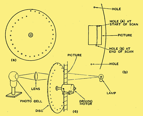
Fig. 10. - The-The scanning mechanism employed in simple television apparatus is shown diagrammatically. At (a) the arrangement of holes in the Nipkow disc can be seen, and (b) shows how the picture is traced by the successive holes. The complete arrangement for transmitting a picture from a cinema film is illustrated at (c).
The process described above in connection with Fig. 8 (i.e., of dividing the picture up into a number of lines or strips and transmitting, in rapid succession, electrical impulses which correspond to the light and shade of each strip) is usually called scanning, and this, together with the use of a light-sensitive device, such as the photo-electric cell of Fig. 9, is the basis of all methods of television.
In its simplest form scanning such as that discussed can be carried out by means of a Nipkow disc, which, as already stated, was invented fifty years ago. This is shown in Fig. 10 (a), and is seen to consist of a rotating disc with a number of holes arranged in the form of a one-tum spiral. The picture is enclosed in a frame arranged so that only one hole at a time can be on the picture, as shown in Fig. 10 (b). The number of holes is equal to the number of scanning lines into which the picture is to be broken up, so that the number of holes multiplied by their width must equal the width of the picture. The distance between the holes around the circumference of the disc is equal to the height of the picture in its frame. The action of two successive holes in passing from one strip of the picture to the next is also seen in Fig. 10(b). For example, at.the instant the hole B finishes its journey over the picture (assuming the disc to be rotating clockwise) the hole A is just coming on to the picture, and will traverse a path across the picture immediately adjacent to that of B.
An arrangement which could be used for the scanning of a cinema film is shown in Fig. 10(c) Light from the lamp is directed through the film, which is, during the time, standing stationary in its frame. After being scanned by the disc the light falls upon the photo-cell, and it will be seen that the illumination of the cell at any instant depends upon the light and shade encountered by each hole as it passes over the picture, as already considered in connection with Fig. 8. From what has previously been said it will be clear that the narrower the width of the scanning strips the greater will be the detail and definition of the picture.
It will also be clear that the photo-cell output current can be amplified to any requisite degree and then used to modulate the carrier of a wireless transmitter exactly in the manner discussed in connection with a telephone channel. Such differences as may and do occur in practice are due entirely to the different range of modulating frequencies involved in television as compared with sound broadcasting. This subject will be discussed in greater detail later.
Reconstructing the Picture
In the radio receiver there is again no essential difference apart from the different range of modulating frequencies involved, so that we need not meantime consider the circuits of the transmitter and receiver, but turn directly to the television equivalent of the loud speaker. Primarily this consists of a device giving a light response varying in sympathy with the operating currents which it receives. As these variations are very rapid this rules out all ordinary incandescent lamps, and it has been usual to employ a lamp of the gas-discharge type, such as the neon tube, although within the past few years more powerful lamps have been devised, using, for example, mercury vapour as the gas. The lamp is generally connected in the anode circuit of the output valve of the receiver, and gives, therefore, some intermediate intensity of illumination according to the normal strength of the anode current. The television signal then causes fluctuations of the current, and the light varies in sympathy. Thus, if we watch the lamp we may see - or rather be dimly conscious of the fact - that it duplicates all the light variations in the transmitted picture, but they do not form any intelligible picture because the picture has been broken into strips at the transmitter. It is therefore necessary to reassemble these strips at the receiver.
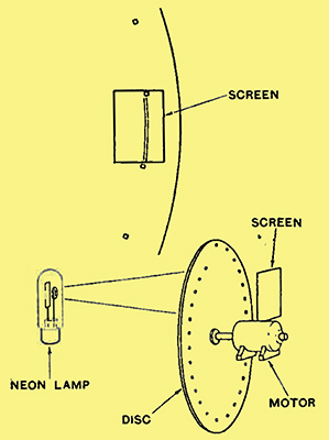
Fig. 11. - The upper portion of this drawing shows the manner in which the holes in the scanning disc pass over the viewing screen, while the lower portion illustrates the arrangement of the apparatus. The light from the neon tube passes through the holes in the disc and falls on the screen. The position of the spot of light at any instant is determined by the precise position of the disc.
In its simplest form this can also be done by means of the Nipkow disc, the whole process being, indeed, the exact reverse of that at the transmitter. The schematic arrangement is shown in Fig. 11, where the disc is interposed between the viewing screen and the neon lamp so that the light from the lamp can fall only upon the viewing screen through one hole at a time. The disc must be identical with that used at the transmitter, and it must rotate at exactly the same speed. But a much more stringent requirement is that at any instant when any particular hole is just beginning to scan the picture at the transmitter the corresponding hole at the receiver must also be at exactly the same point. This means that the two discs must be absolutely synchronous.
Persistence of Vision
In this way the strips into which the picture was broken up at the transmitter are, reconstituted in their correct relative order and positions, and are so placed on the screen of the receiver. An important point, however, must here be mentioned. This is that the effect is that of a single point of light which moves across the successive strips of the screen in the sequential order necessary to reproduce the picture. Since the light spot is only at any single point at any single instant, how does it give the eye the impression of the whole picture?
It becomes possible because of a most valuable property of the eye, usually described as persistence of vision, without which there would be no television and, for that matter, no cinema. If a very brief impulse of light is imparted to the retina of the eye the conscious impression of this light that is, its effect on the brain as the real seat of consciousness and sensation persists for some time after the actual light has ceased.
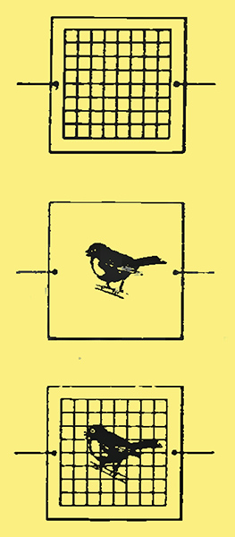
Fig. 12. - The bird in the cage illustration of persistence of vision.
One of the simplest and yet most convincing illustrations of persistence of vision is the well-known 'bird in the cage' illusion. This is illustrated in Fig. 12, where we have a square card with a bird-cage on one side and the bird itself on the other. Small holes near the edge of the card let it be twirled rapidly by strings in a manner familiar to all readers young and old. The eye sees each side of the card in such quick succession that the impression of one side is still being received when the impression of the next side arrives. The illusion is then conveyed of the bird being inside the cage.
It is due to this same property that we are able to get the impression of continuous motion on the cinema screen. Many readers will already be acquainted with the fact that on the cinema screen the pictures are presented at the rate of twenty-four pictures per second. Each picture is shown complete for half of this time, that is, for 1/48th of a second; the light is then cut off for the next 1/48th of a second, during which time the eye carries on the impression until the next picture. This is then presented in the same way, together with whatever change of position has occurred due to the movement of the scene, and the sense of smooth motion is obtained.
In the case of picture reconstruction which we have considered this persistence has the effect that, by the time the travelling spot has reached the last stages of scanning, the impression of the beginning of the scan has not yet faded from consciousness, and the idea of a complete picture is conveyed.
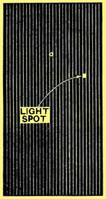
Fig. 13. - At any instant the picture consists of no more than a single minute spot of light, but, owing to the retentivity of the eye, the movements of this cannot be distinguished, and the effect of a steady picture is obtained.
The effect of persistence varies according to the brightness of the light, as does also, of course, the inherent brightness appreciated by the eye. This matter of illumination is one of the fundamental difficulties of television, and can again be illustrated in relation to the cinema. In the case of the film the screen is completely illuminated for 1/48th of a second. Assuming, for the moment, the same rate of picture presentation in television, it will be seen that during the time devoted to the scanning of a whole picture a single small spot of light only lingers for a very brief instant on each point of the viewing screen. This is shown in Fig. 13, where we imagine the light spot to be passed successively along each of the black strips. It will thus be seen that the actual degree of illumination imparted to the whole picture is very small indeed. This has the immediate effect of restricting the size of the reproduced picture, while it will be appreciated that the same difficulty of the short time during which each point of the picture is illuminated has also the effect of introducing difficulty at the transmitter, and calling for a very strong source of light to effect relatively simple scanning of the type shown in Fig. 10.
The Need for Synchronism
Reference has been made above to the need for exact synchronisation between the scanning discs at transmitter and receiver. This is of fundamental importance and represents another of the practical difficulties of television, especially when we are concerned with the synchronising of mechanical systems, such as motor-driven discs of considerable inertia. The actual methods by which such synchronising is secured in practice need not be more fully considered at this point, but will arise later in our considerations of more modem (cathode ray) methods, where, fortunately, the requirements, although quite as strictly necessary, are more easily attained practically.
Parenthetically one can hardly refrain from commenting that the principle of building up a picture synchronously line by line is nearly a hundred years old, and was suggested in 1843 and actually tried in 1847 in the relatively early days of the electric telegraph. At the sending end a metal cylinder had a simple design inscribed on it by an insulating material such as shellac. The cylinder was then rotated with a pointed stylus travelling over it; after the manner of the old-fashioned phonograph record, and the shellac patches interrupted the electrical current sent out to the line. At the receiving end a stylus was similarly moved over a cylinder synchronously rotated but carrying a chemically treated paper, the varying currents through which caused varying discolourations reconstituting the design. The whole difficulty at the time was that of synchronising, but this crude method forms the genesis of our present picture or facsimile methods of transmission. The reader will also appreciate the similarity of the fundamental process to that of television except for the enormously greater speeds at which, in television, we have to do the scanning of our picture.
Direct Scanning of a Scene
The method of. scanning with a Nipkow disc has only been described above in relation to a celluloid film where light of varying brightness is passed to the photo-cell in accordance with the varying opacity of the film, producing a correspondingly varying current which can be used to modulate a radio transmitter. A somewhat similar method can be used for the scanning of a direct object or scene. The original method used, for example, by Baird, consisted of floodlighting the object by an intense illumination - so intense that, in the first place, only dummy figures could reasonably be expected to stand it. The object was then scanned point by point by the Nipkow disc, and the light reflected from the various points of the object under view passed on through the disc holes to the photo-electric cell. The variations of light so received then produced electrical variations in exactly the manner already considered.
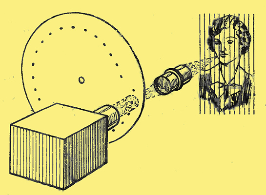
Fig. 14. The principle of light-spot scanning.
The disadvantages of such intense illumination led to the development of what is now known as the 'light-spot' method of scanning. An outline of this method is shown in Fig. 14. Instead of floodlighting the object or should one say subject? a much feebler light is used and directed on to the object point by point through the holes of the Nipkow disc. The spot of light is thus caused to traverse the actual object in a series of lines in exactly the manner already considered in relation to a picture. The light reflected from point to point of the object is then collected by the photo-cell and transformed into current variations in the usual manner.
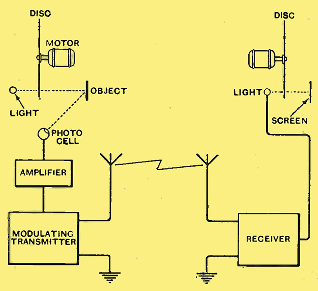
Fig. 15. - Essentials of a mechanical scanning television system, transmitting and receiving.
The essential outline of this method is illustrated in Fig. 15, which should be readily followed from what has already been said. The diagram is, of course, only the roughest outline. The arrangement of the receiver in particular is now obsolete, but is given here because of its value as illustrative of the principle involved in a television system.
Mirror-Drum Scanning
In the history of television numerous variants of the scanning disc have been proposed and tried. In view of the present tendency to depart from mechanical methods for high-definition television no useful purpose would be served by further detailed consideration of them. The disc principle still forms one method of several that may be used for the much more rapid scanning of film for a high-definition transmission such as we hope soon to have. Its future in the scanning of direct scenes for a high-definition service must mean-time, however, remain a matter of doubt.
Another important mechanical method of scanning is that using small mirrors arranged, for example, round the outside of a narrow revolving drum. If each successive mirror is arranged at a slightly different angle, any light reflected from each in turn is directed in a slightly different direction, and can be made to fall over a translucent screen in a series of lines in a manner similar to that already considered (in Fig. 11) for disc scanning at the receiver. The mirror principle can, of course, be used for transmitter or receiver, but it is only in the latter application that it has appeared in British practice. This is in the Baird. mirror-drum receiver, which is, at the time of writing, the standard instrument for receiving the 30-line transmissions now made by the BBC.
Light Modulation
Before we can consider this method of scanning, however, it is necessary to deal with an important method of light modulation which is used with it in the Baird receiver. This is the method employing the Kerr cell.
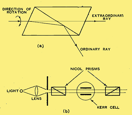
Fig. 16. - (a) Principle of the Nicol prism. (b) Nicol prisms and Kerr cell arranged for the modulation of a light of constant intensity.
In the receiving systems already mentioned we have considered only gas-discharge lamps whose intensity of illumination could be varied by the current passing through them. The Kerr cell uses an entirely different principle, to understand which we must make a short incursion into optics. Ordinarily, if we take a source of light we have radiation in every direction. certain crystals, however, have the remarkable property that a light-wave motion in only one or two directions can be projected through them. For example, when light is projected through a crystal of the material known as Iceland Spar, its path is refracted or broken up into two rays. One of these is found to obey the regular laws of optics and is called the ordinary ray; the other is called the extraordinary ray. These conditions are shown in Fig. 16 (a). If the crystal is rotated about its optical axis (i.e., in the direction shown in the diagram), the ordinary ray remains fixed but the extraordinary ray turns with the crystal. The arrangement shown in Fig. 16 (a). using this principle is known as the Nicol prism, and the extraordinary ray from one such prism can be passed through another prism provided the two are in the same relation to this extraordinary light beam. If the first prism be rotated, the light transmitted through the second prism will be much reduced.
This provides a means of varying or modulating the light through the second prism, but it is clearly inconvenient to do it by rotating the first prism. Instead, the rotation is done by means of a Kerr cell. This is shown in Fig. 16 (b) in relation to the two Nicol prisms. The cell consists of a number of plates arranged in capacitor fashion and immersed in rectified nitro-benzene. It is then found that the application of a voltage above a certain critical value has the remarkable property of twisting the extraordinary beam of light passing between the plates, so that the light passing through the second prism is reduced, just as if the first prism had been bodily twisted in the manner considered above. The complete system is remarkably rapid in its action, and thus acts an an instantaneous light-valve. The signal voItages are applied to the plates of the Kerr cell, and thus cause variations of the light passed through the second Nicol prism to produce the modulation necessary for the reconstruction of the television image.
The Baird Mirror-Drum Receiver
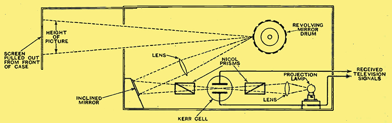
Fig. 17. - Illustrating the working of the Baird mirror-drum Televisor.
The variable-intensity light passed out from the second Nicol prism is then directed on to the mirror drum of the scanning system, whence it is reflected on to the translucent screen to form an image, line by line, after the usual manner of recomposition. The actual arrangements of the Baird mirror-drum receiver are shown in Fig. 17, while a photograph of the interior components, omitting the screen, is seen in Fig. 18.
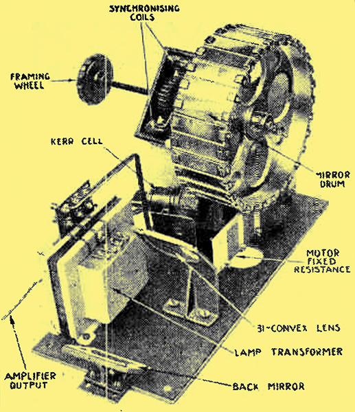
Fig. 18. - The important parts of the Baird projector receiver, using Nicol prisms and Kerr cell, with mirror-drum scanning.
The present transmissions by the Baird process made by the BBC are on what is now generally called a low-definition basis, although we shall see later that this is all that can ever be hoped for in the ordinary medium-wave broadcasting band of wavelengths. The picture on the mirror-drum receiver of Figs. 17 and 18 is 9 inches high by 4 inches wide and is scanned in thirty vertical lines after the manner originally considered in connection with Fig. 8. From the 'dot' arguments already given in connection with Figs. 5, 6, and 7 it will be appreciated that the division of a picture 4 inches wide into only thirty lines causes the reproduction to be coarsely grained and lacking in fineness of detail, exactly as we have considered in relation to the half-tone block. The ratio of height to width, viz., about 2.25 to 1, is an awkward one for general scenes with any breadth of aspect. It is a suitable enough shape of picture for the viewing of a single person who is (normally) a good deal taller than he is broad, and, in particular, there is little doubt that it was a good enough shape for the type of material suitable for presentation by a low-definition system. But for a scene containing any degree of back and forward motion it will be seen that the tall, narrow picture is quite unsuitable, and the tendency of recent times, particularly in connection with systems of higher picture definition. has been towards a shape of picture already hallowed by the cinema and having a breadth-to-height ratio of about 4 to 3. This ratio, by the way, is frequently called the 'aspect ratio' of the picture. It should also be mentioned at this point that this change of shape has been accompanied by the general, indeed almost universal, tendency to scan along the longer dimension of the picture, that is to say, horizontally, a tendency which has been encouraged also by technical considerations which will shortly be obvious.
In the present Baird thirty-line system the pictures are presented at the low rate of twelve and a half per second, which is responsible for a severe degree of flicker, since it is approaching the extreme limits of visual persistence. Cinema-goers may recall that the old silent 'flicks' were presented at the rate of sixteen per second and still suffered a good deal from flicker. The addition of a sound track on the advent of the 'talkie' demanded an increase.in the length of film used per second, and drove up the picture speed to twenty-four. The improvement of the higher 'framing speed' or rate of picture presentation, as regards reduction of flicker, is one which must be within the memory of all adult picture-goers.
To complete our brief consideration of the present Baird thirty-line system it is necessary to mention a point which is of great importance in the matter of synchronising. This is the fact that the top of the picture contains a narrow black horizontal band. This is done deliberately for the introduction of a synchronising signal. At the top of its sweep the light spot is marked out and there is a momentary period of darkness when no light is reflected on to the photo-cell, and no picture-modulation current is, therefore, sent out. During this period, however, the transmitter mechanism sends out a distinctive impulse of its own, and the reception of this at the correct instant is used to control the position and speed of the receiver mechanism.
Scanning a Cinema Film
In the present position of the art of television much of what has been written above is largely of historical interest, although it has been used throughout in illustration of principles which are equally applicable to high-definition television practice. Before leaving mechanical scanning systems, therefore, it is desirable to consider some of the methods which have been used particularly in relation to the scanning of films and which are broadly illustrative of the principles of film-scanning which we are likely to see in future use.
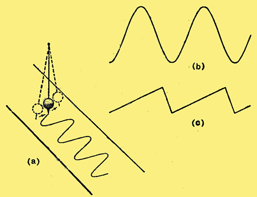
Fig. 19. - Illustrating simple sinusoidal variations (a) and (b), as compared with a 'saw-tooth' motion.
To help us to understand a type of motion that we are to meet a great deal in this and in subsequent connections, let us consider for a moment the manner in which a pendulum oscillates about its support. This is illustrated in Fig. 19 where we imagine the 'bob' of the pendulum to be a bowl of fine sand which can trickle gently out of a narrow pointed jet. If, while the pendulum is swinging, we steadily draw a strip of paper along under it, we can use the trickling sand to trace what becomes a curve of 'motion against time' of the pendulum, as shown in Fig. 19 (a). This is the simple sine-wave, with which the more technical reader is already familiar, and is typical of most natural modes of oscillation, mechanical or electrical. Plotted as a simple graph against time, our sinusoidal curve, therefore, appears as shown in Fig. 19 (b). Now suppose that, by some means - magic if you like - we can cause the pendulum, instead of swinging regularly in this manner, to go relatively slowly, say, from left to right and then suddenly and quickly return from right to left. It will then be seen that our sinusoidal curve of Fig. 19 (b) will no longer represent the law of the pendulum motion, which will, instead, be shown by the graph of Fig. 19 (c). From its obvious shape, this law of variation is known as a 'saw tooth'. While the sinuous motion of Fig. 19 (a) and (b) represents what is, perhaps, a more widely general natural law, the alternation of slow and abrupt motion mentioned in connection with Fig. 19 (c) is one that can be obtained with various mechanical systems, and more particularly with many different electrical circuits. For that matter it will be appreciated that this law accurately represents the manner in which our scanning spot of light traces its path in Fig. 13 under the influence of the Nipkow disc, moving steadily along one strip and then suddenly shooting back to the beginning of the next.
A method of scanning a cinema film is shown in Fig. 20. For this purpose the film is drawn through at a uniform speed and not in jerks as it is in the normal practice of cinema projection. This drawing through at uniform speed is typical of all methods of drive for television film-scanning. A source of light is directed on to a curved mirror, from which it is reflected on to the film in a point as shown. Between the film and the photo-cell is a collecting lens which, in the absence of a film or in a transparent piece of the film, turns the point of light into an image of the mirror focused on the cell. This is done to ensure that movement of the mirror does not cause movement of the light spot on the cell, and so that the light on the cell is not modulated by movement of the beam but only by changes of the intensity of light through different points of the film. The mirror is vibrated back and forward, preferably in accordance with a saw-tooth type of movement. Thus, in moving, say, from left to right the light-spot will explore a line along the film and the actual light reaching the photo-cell from instant to instant will vary in accordance with the varying density encountered. By the time the spot has travelled relatively slowly from left to right and done its abrupt return to the left, the film, under the influence of its continuous motion, will have moved on a little so that the next left-to-right movement of the spot will scan a new line on the film and so on. If the film is moved at a continuous rate (say, that corresponding to twenty-five pictures per second, which is now adopted in British television practice) it will be seen that the number of horizontal scanning lines will depend on the speed at which the mirror does its saw-tooth vibration.
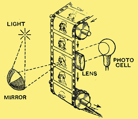
Fig. 20. - A method of scanning a cinema film for transmission.
As has already been considered in the case of the 30-line transmission, a very narrow vertical black band at one end of the picture, that is at the end of each line scan, can be used to control the sending out of a synchronising impulse between successive scanning lines. The small gap between picture 'frames' on the film can also be used for the sending out of synchronising impulses to control any slower movement concerned with the rate of picture presentation. Both of these are, indeed, now used in high-definition systems.
It is useful to note that this method is typical of the cathode-ray methods of film-scanning which we shall consider later, and which are certain to be prominent in our future high-definition systems. It will also be readily seen that the Nipkow disc principle can be adapted for horizontal scanning of a film, and this has been the method so far used by the Baird Company in the development of its high-definition system. For these higher speeds, however, mechanical scanning at the receiver has been abandoned.
Rapid Fluctuations
In this general review of the subject the next point that calls for attention is the rate at which the current impulses in the photo-electric cell may possibly vary. This is equivalent to asking what is the maximum frequency of the variations of current in the photo-cell which we have to use for the modulation of our radio transmitter in the manner already considered. The answer constitutes one of the greatest difficulties of practical television!
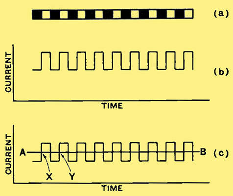
Fig. 21. - A series of black and white squares (a) gives rise to a photo-cell current of the type shown at (b). This is equivalent to a direct current, represented by AB in (c), with a superimposed alternating current.
Suppose that we wish to transmit a chessboard design in which the black and white squares are the same size as our scanning point. The variations in light and shade for a single (horizontal) scanning line are shown at (a) in Fig. 21, and the corresponding variations of photo-cell current at (b). In this particular case eighteen squares are shown alternately black and white. There are, therefore, eighteen changes, or eighteen rises and falls of current through the cell. As is shown in Fig. 21 (b) these are variations in strength of an existing unidirectional steady current. They are, nevertheless, exactly the equivalent of an alternating current of the square-topped wave shape shown, super-imposed on a steady direct current, as illustrated in (c), in which the line AB represents the steady current for this type of picture, that is to say, it is effectively the 'zero' of the alternating current wave form. Indeed, after passing through a suitable transformer, or after a stage of the inevitable valve amplification, we lose the steady current represented by the height of AB and are left with only the alternating component which is handed on for modulation of the transmitter. It will thus be seen that one complete alternation of current occupies the time from X to Y, and for eighteen squares, as illustrated, we have nine such alternations. Assuming, therefore, for the sake of illustration, that our design consists of a total of eighteen lines of chessboard design, each scanned in the manner indicated, we see that in each complete scan we should have 18 × 9 = 162 square-topped alternations in each complete picture frame, and 162 × 25 = 4,050 per second for a picture rate of 25 per second. But the scanning rate of eighteen lines is, of course, much too coarse for practice. Thus, instead, if we consider a square chessboard pattern, each line consisting of a hundred squares, the squares, as before, being the size of the scanning spot, by the same reasoning we should have 100 × 50 = 5,000 square-topped alternations per frame and 5,000 × 25 = 125,000 per second.
Wide Frequency Spread
It is admitted that the chessboard represents the very worst case of abrupt transitions from black to white, but the above would be typical of the maximum frequency likely to be met, at the scanning rate considered, at any point where such abrupt transition occurred. It therefore represents the highest fundamental frequency likely to be met in our modulation and requiring to be satisfactorily handled for maximum resolution or fidelity of response. Moreover, technically informed readers will realise that it is only the fundamental frequency and that strong odd harmonics up to the fifth and seventh are actually present in the square-topped wave shape.
Even if we do realise, however, that compromise practically demands that these higher harmonics should be ignored, we are still faced with the fact that very high modulating frequencies are necessary. Taking concrete examples of the highest fundamental frequency involved in a few typical scanning rates of 4/3 ratio pictures presented at twenty-five pictures per second, we find the following values:-
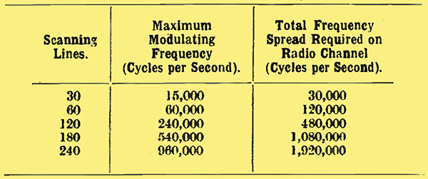
It has already been pointed out that high-quality sound broadcast may be obtained with modulating frequencies up to 10 kHz, and a frequency spread of a total width of 20 kHz. It will thus be seen that a 180-line television system would occupy as much space as fifty-four sound-broadcasting stations and a 240-line system as much as ninety-six. This instantly explains the utter impossibility of accommodating them in the medium-wave broadcasting band. Another difficulty is that, even if we could so accommodate them, the apparatus for tuning to the carriers in this region would be quite unable to cope with these great spreads of frequency.
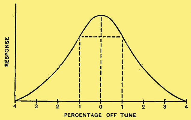
Fig. 22. - Resonance curve of a broadly tuned radio circuit.
This is very simply illustrated by drawing the response curve or, as it is usually called, the resonance curve of a fairly broadly tuned radio circuit, as shown in Fig. 22. If we assume this to represent conditions in the medium-wave broadcast region, a central or carrier frequency of one megacycle (300 metres) would have a fairly uniform response over a spread of 20 kHz, representing 1% detune on either side of the centre. On the other hand, at 4% the response is cut off completely.
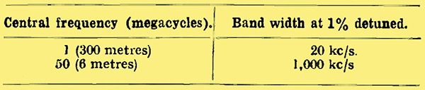
But if we take a very much higher central frequency, such as 50 MHz corresponding to a wavelength of 6 metres, we find that our 1% detune on either side now represents a total spread of 1 MHz of fairly uniform response. This is much more like the values of frequency spread given in the above table, and shows fairly readily that only in this region of the so-called 'ultra short waves' can we hope to accommodate the great spread of frequency necessary for high-definition television.
Why the PMG's Committee Became Necessary
The foregoing general considerations - briefly as they have had to be outlined in the scope of this small booklet - now put us in a position to consider the real difficulties of television and to see the need for the intervention of a committee such as the Postmaster-General appointed last year to help decide the lines on which further orderly development of television should be encouraged.
The intricate nature of the sense of vision, as compared with sound, immediately raises inherent difficulties. In the case of sound the range of frequencies to be transmitted by modulation of our radio transmitter is simply and directly governed by the sound itself and leaves us no choice in the matter. Moreover, we have shown that the most complex sounds or mixtures of sound amount to only a single instantaneous effect. With vision there is no inherent frequency associated with the scene and capable of being directly translated into electrical effects for the modulation of our transmitter. Moreover, the process of vision, instead of amounting to a single effect, consists of millions of effects all existing at once and all requiring to be separately appreciated for the full enjoyment of the sense. Thus it comes about that in our present state of knowledge we are driven to the process of point-by-point scanning with all the difficulties that have been outlined. And unless some new physical principle is revealed which is at present quite undreamed of in our philosophy, progress appears to lie along the lines of the development and improvement of our existing methods.
In the natural way of things, this progress began with the development of low-definition working such as the 30-line system which the BBC has now transmitted for a few years. But it has long been realised that the severe limitations of subject-matter which such a system was capable of handling imposed corresponding limitations on its entertainment value and its domestic appeal. Many people in many lands have been working towards the improvement of television, and the schemes propounded have been almost innumerable. On this subject the PMG's recent Committee on television offers the comment: 'The number of patents relating to television is very large, and in regard to many of them there are conflicting views as to their importance and validity'.
In this country alone, for example, at least four or five different concerns have been engaged on various forms of television development.
But within the past few years one factor has stood out most prominently. This has been the development of the instrument known as the cathode-ray tube, which, although by no means new, has within recent years undergone very rapid progress in design. It is interesting to recall that in 1908 the late Mr A A Campbell-Swinton, a well-known British engineer, suggested in a letter to Nature that the problem of television might be solved by the use of this device, then rather by way of being a laboratory toy. The advent of this instrument as an everyday working tool has led many, indeed most, television experimenters to look to it as the means of deliverance which this prophet foresaw.
The mere march of technical progress was, therefore, of its own accord, leading many workers along very similar lines, but some form of co-ordination was clearly necessary in order to ensure that these lines of development were sufficiently unified to represent the basis of a public service. In other words, in view of the latitude with which the requirements of nature could be interpreted by different workers, it became necessary that administrative authority should formulate a specification of requirements for the television engineer which nature had failed to supply. This has been provided by the report of the Postmaster-General's Committee summarised in The Wireless World of February 8.
As the cathode-ray tube is certain to be the picture-reproducing agency in our new home television receiver, the present point in our discussion is the appropriate place to consider this very useful and versatile device. Incidentally, readers who are desirous of more information on the general uses and applications of the tube are reminded that a short series of technical articles on the oscillograph appeared in issues of The Wireless World for January 4, 11, and 18, 1935.
Historical
One of the first things that one has to say about the cathode ray tube is that its name is not a very good one. The name 'cathode rays' was used by Sir William Crookes many years ago to describe the rays given off from the negative electrode in a vacuum tube under certain conditions. We now know that what was given off were actually electrons, and that a better name for it would have been the 'electron beam' or 'electron jet' tube, but the name 'cathode ray' sticks. The remarkable fact which was obvious about these rays was that they could be bent about by electric or magnetic fields, and it was this property that, in 1897, led the German, Braun, to suggest that this bundle of rays might be used as an indicating instrument, particularly as an 'oscillograph' for the visual examination of alternating or oscillating current. By this time it was also known that when this bundle of rays hit the end of the bulb in which they were produced they had the remarkable property of causing certain materials coated on the inside of the glass to glow, or to 'fluoresce' in different colours, according to the material. This was readily visible from outside and became the dial, as it were, of Braun's voltmeter, the pointer mechanism of which was the bundle of cathode rays. At this time the cathode was cold and the electrons were 'persuaded' from it by the sheer 'brute force' of a very high voltage. Once it was known that the bundle of rays was a stream of electrons, it was equally obvious that an easier method of obtaining a copious stream of electrons was to make the cathode in the form of a wire or thin ribbon filament and heat it by a current, just as we do in our wireless valve.
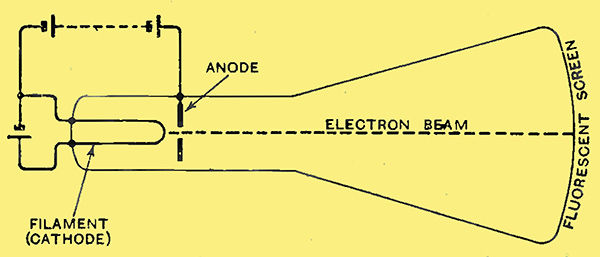
Fig. 23. - The elements of the cathode ray tube.
This brings us to Fig. 23 as representing the stage in which the cathode-ray tube languished for many years as an interesting but undeveloped device. In the form shown it consists essentially of two electrodes, a cathode and an anode. The cathode (filament) is heated by current from a battery, and gives off electrons. These are drawn to the anode, which is maintained at a positive potential to the cathode, exactly as in a wireless valve. The anode is usually in the form of a disc with a central hole (as illustrated in Fig. 23), or of a short, narrow tube. Some of the electrons, indeed a great many of them, arrive from the filament with sufficient speed to shoot right through the anode aperture and to emerge into the main bulb beyond it, while, of course, some are directly caught by the anode and form an anode-circuit current just as in the two-electrode valve or diode. Of those that shoot through the anode, some tend to get back to the anode as directly as they can, but many are projected along the length of the bulb. In their journey, however, they mutually repel each other, in accordance with the ordinary electrostatic laws of similar charges, so that the beam tends to be broad and diffuse by the time it reaches the fluorescent screen on the end of the bulb.
Focusing the Electron Beam
With the simple tube illustrated in Fig. 23 various artifices could be applied to ensure that most of the electrons were shot off from the filament in the direction of the anode aperture and also to keep them together so that they arrived at the fluorescent screen in a sharp-pointed beam, just like a well-focused point of light, and giving, indeed, a sharp spot of light on the fluorescent screen. These tricks were, however, both difficult and tedious, and the instrument was very little use as anything other than a demonstration of the principle. The first notable step which brought it to the level of a reliable indicating instrument was the devising of a stable and convenient method of focusing the beam in this manner. This was done by introducing a small trace of an inert gas (Argon was actually first used) which was ionised by the impact of electrons and formed a sort of positive core along which, once established, the electrons could be guided. With a tube of given dimensions and with a given amount of gas left in it, it was then possible to adjust the filament current as a single control and bring the beam to a sharp focus on the fluorescent screen. It is to be noted, incidentally, that the beam was not the same width all along its length; as shown in Fig. 23, this was immaterial so long as it came to a sharp point-focus on the screen. This method of control was introduced in the Western Electric Tube, which appeared early in 1923 and was the first really practicable realisation of the cathode-ray tube as a working device.
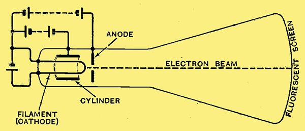
Fig. 24. - Use of a negatively charged cylinder to concentrate the electron beam.
The next important step was one due to a young German, Manfred von Ardenne, about five or six years ago. This is illustrated in Fig. 24, and consists of surrounding the filament by a cylinder which is kept negative to the filament by an amount of 1/10th or 1/20th of the voltage by which the anode is positive. The negative charge on the cylinder exercises an immediate constricting effect on the electrons emitted from the filament and greatly assists their acceleration through the anode aperture. (Incidentally, also, it protects the filament from what is called bombardment by ions, and thus lengthens its life.) The gas-ionising effect was still maintained and serves as a partial control of the final focus of the beam, this being effected jointly by adjustment of the negative potential of the cylinder and the heating current of the filament. The arrangement of the electrode system shown in Fig. 24 still remains the typical construction of the 'soft' cathode-ray tube now in use for an immense number of laboratory, industrial and other measurements (cf, Wireless World, January 4th, 1935). The great feature of the device which has led to those many applications is that the electron beam can be used as a moving pointer entirely free from inertia and, therefore, capable of movement at extremely high speeds. It is this same property, of course, that has led to its use in television, where we have already seen that rapidity is the essence of the contract. The soft type of measuring tube illustrated in Fig. 24 is not, however, entirely suitable for practical television, for reasons which we shall consider later.
It will be seen that the system of electrodes - filament, cylinder and anode - shown in Fig. 24 has as its sole function the work of shooting an electron beam along the tube. For this reason it is usually called an electron gun. What we do with the beam after it emerges from the gun is the next story.
No attempt will be made here to deal with the details of the circuits for deriving the various voltages for operating the tube, although these follow very simply on the lines of the voltage-supply units for our wireless sets. The voltages concerned are, of course, much higher, but the currents are very small and the 'eliminator' can be of very simple design; for example, a half-wave rectifier with the most elementary smoothing. In any case, the apparatus for obtaining the supply from the AC mains will be an integral part of the home receiver of the future, and exact details will vary with tubes of different make. It is desirable, however, to emphasise that this high-voltage apparatus can easily be made completely fool-proof in use, and this will necessarily be an essential point of design in the receivers put on the market to receive the new service.
Deflecting the Beam
It has already been said that the function of the electron beam is to serve as an indicating pointer, whose motions become visible on the fluorescent screen at the end of the tube. This is its use in the general application of the lube to electrical and allied measurements, and it is also how we use it in television.
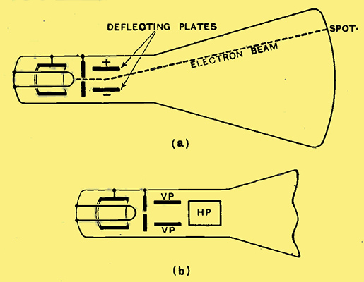
Fig. 25. - Deflection of electron beam by plates within the tube; (a) one pair of plates deflecting beam vertically, two pairs of plates, VP for vertical deflection, and HP for horizontal deflection.
In considering the manner in which the beam is used we have to remember that it consists of a beam of single and individual electrons, moving along in what is effectively a continuous stream. Each electron consists of a negative particle of electricity. If, therefore, we introduce two small rectangular plates, one above and one below the beam, as shown edge-on in Fig. 25 (a), it will be seen that a voltage applied as shown by the + and - signs (i.e., making the upper plate positive) will have the effect illustrated. The electrons in the space between the plates will be repelled from the lower plate and attracted to the upper plate according to the strength of the voltage. After emerging from the plates the beam will resume its straight path, but the spot on the fluorescent screen will be. moved upwards as shown in the figure. Reversing the voltage will have the effect of reversing the movement of the spot, and it will be seen that the process of deflecting the beam close to its emergence from the electron gun has the effect of giving a large leverage in the amount by which the visible spot is deflected on the fluorescent screen.
But, besides moving up and down in this way, the beam can also be made to move back and forward. This can obviously be done by another pair of plates as shown at HP in Fig. 25 (b), one of which only is seen obscuring the other. Exactly the same leverage is obtained as before, and it is to be noted that the amount by which the spot is deflected on the fluorescent screen is directly proportional to the voltage, i.e., if 25 Volts applied between one pair of plates deflect the spot 25 millimetres, 50 Volts will deflect it twice as far.
Another method of deflecting the beam for useful work is by means of current-carrying coils usually placed outside the tube. This is due to the fact that the electron beam is, as has been mentioned, a stream of moving electrons, and this is exactly the equivalent of an electrical current, except that it is not being carried along in a wire but in a vacuous space. It is well known that a wire carrying a current can be deflected by a magnetic field, and the fact is regularly used in our moving-coil voltmeters, ammeters and loud speakers. In the case of the cathode-ray tube it is usual to utilise this fact by placing two coils in series and arranging them on each side of the tube, as shown in Fig. 26. This, of course, would only correspond to one pair of plates, and a second pair of coils mounted at right angles would be necessary for imparting movement to the spot in the other dimension of deflection.
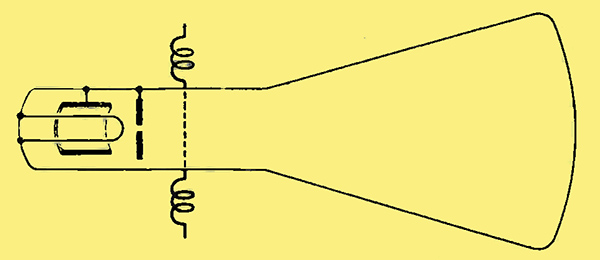
Fig. 26. - Deflection of electron beam by current-carrying coils outside the tube.
From the foregoing it will be seen that the beam can be moved either vertically or horizontally. As a matter of fact, it can be moved in both directions at once, or, more strictly, it can be moved in a resultant manner which is the combination of both directions of movement. It is this extraordinary flexibility which makes the cathode ray tube such a valuable instrument and has led to its being used for an amazing number of purposes that could not be satisfied by any other instrument. And exactly that same flexibility is the quality that makes it so valuable in television. One of its very useful qualifies is that, since the beam is composed of very minute electrons, it is devoid of inertia and can be moved either in one direction or back and forward at very high speeds.
This latter quality can be illustrated (and incidentally serves as an illustration of persistence of vision) by joining one of the deflecting systems, say, the horizontally deflecting plates HP of Fig. 25, to a source of voltage whose frequency can be varied from a very few cycles per second up to many thousands of cycles per second. At the lower frequencies the spot is seen to vibrate back and forward quite slowly and its movements can easily be followed by the eye. This continues until we get up to a frequency of about sixteen per second, when the eye is no longer able to follow these individual movements, although it is still possible to detect a slight flickering effect. As the frequency is increased above, say, twenty-five or so, even this flickering effect ceases to be appreciated, and the back and forward movement of the spot simply appears as a continuous line, this remaining the case as the frequency is steadily increased to many thousands or hundreds of thousands of cycles per second.
A New Reproducer for Television
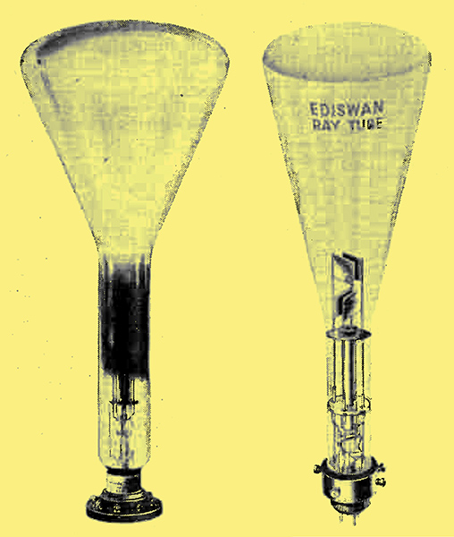
(Left) The large Cossor high-vacuum tube with a sensitive screen of 12.75 ins. diameter. (Right) The Ediswan hard tube, available with screens of 14 cm and 20 cm diameter.
Now it has been shown that the electron beam produces a spot of light on the fluorescent screen or the tube (which can be seen viewing the tube from outside) and that this spot of light can be moved about at extremely high frequencies. It will thus be seen that these two properties form the essentials of a television scanning system. The remaining property which is necessary is that we should be able to vary the strength of the light-spot caused by the beam, in order to reproduce our picture modulation. This also can be done, so that in the cathode ray tube we have all the essentials of a television reproducer, indeed of the reproducer that is certain to be used in our home television receiver under the proposed new high-definition service.
One obvious method of varying the intensity of the light-spot is to vary the actual number of electrons reaching the screen from instant to instant in accordance with our picture modulation. Unfortunately, this cannot be done satisfactorily by means of the ordinary type of soft-vacuum measuring tube which we have hitherto considered and illustrated in Fig. 24. This, is chiefly due to the fact that, in order to keep the beam sharply focused in a small spot on the fluorescent screen, there is an interdependence between the voltages on the anode and the cylinder. Adjustment of this cylinder voltage is, indeed, one of the two controls of focusing in this type of tube. Thus if we use our picture signals to vary the mean voltage of the cylinder we find that the range of control is extremely small and that any excess of this begins to widen the spot instead of only varying its brightness. It will be seen that this will not give good variation of light and shade for picture reproduction, and that what is wanted is a method which leaves the spot always of the same size but of varying brightness.
This is done by means of what are called hard vacuum or very highly evacuated tubes, which have been somewhat intensively developed in the past two years, and more particularly within the past year or so. At least four different firms in this country have been engaged on the design of this newer type of tube. The difficulty of design is that of obtaining focus of the electron beam, since we do not have the assistance of the gas-ionising method mentioned earlier in these pages. Instead, the electron beam is treated after the manner of a beam of light with various electrodes which act like the different members of a compound optical lens and bring the electron beam to a focus on the fluorescent screen just as the optical lens can bring a beam of light to a spot-focus where we want it. Such electrode systems, on account of this similarity, are, in fact, now usually called 'electron lenses'. Instead of the simple electrode system of Fig. 24, two and sometimes three successive anodes are employed at successively increasing voltages.

Fig. 27.--Ediswan Hard Vacuum cathode ray tube. (a) Skeleton diagram of Electron-Lens system; (b) Construction and mounting of electrodes.
A recent and fairly typical design, due to the Ediswan Company, is illustrated in Fig. 27, where (a) shows the skeleton construction and (b) the detailed structure of the electrode system. In this, as in most of the hard-tube designs, the cylinder then becomes an electrode concerned solely with governing the brightness of the fluorescent spot, and producing wide variation of brilliance over a small range of signal voltage.
The colour of the fluorescent spot on a cathode ray screen depends on the material used, and several materials are available with characteristic colours. The material giving the most bright visual response is zinc silicate, but this gives a green colour which is not very suitable for the purpose of television; Different samples of zinc sulphide give different colours of fluorescence, according, presumably, to traces of mixture or impurity contained. Mixtures of various substances can also be used to give suitable colours, and tubes giving quite good effect of black and white or sepia and white are now available, the general colour effect being, indeed, very similar to that with which we are accustomed in photographic printing papers. It seems that the sepia and white screen is particularly pleasing to the majority of 'lookers-in'.
Scanning with the Cathode Ray Tube
The cathode ray tube has just been shown to have all the essentials of a television scanning and reproducing system, and from what has been said both about it and about the general principles of scanning, the complete process can now be very easily followed.
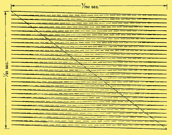
Fig. 28. - Television scanning in a cathode ray tube by two saw-tooth voltages.
In Fig. 28 we trace the path of the spot in scanning a. cinema-shape picture in thirty lines. Beginning at the top left-hand corner the spot travels steadily from left to right and then proceeds to shoot back abruptly from right to left. But during this period it has also been subjected to a slight downward movement so that its next left to right sweep is done slightly below the first, and so on, each left to right sweep being done slightly below that immediately preceding it. This goes on until the thirty lines are completed when the spot proceeds (a) to shoot from right to left, (b) to shoot from bottom to top, and, doing both at once, takes the more or less diagonal path shown in the heavy dotted line from the bottom right to the top left-hand corner.
From what has been said in connection with Fig. 19 it will be realised that the spot has simply done two types of motion, both conforming to the 'saw-tooth' law. One of these was the slow movement from top to bottom, with sudden return from bottom to top, corresponding to the time taken to scan one picture, and lasting, in fact, 1/25th second; the other was the same type of motion but done much more quickly, corresponding to the line scan, so that each motion from left to right lasted 1/ 750th of a second. The fact that the spot is moving downwards during the time of each line is seen in the fact that the lines are not quite horizontal, but it will be realised that with a greater number of scanning lines in the same time the lines will be much more nearly horizontal, and that in a 240-line system this distortion will be quite negligible. An actual photograph of the front of a cathode-ray tube with two-dimensional scanning of this type is shown in Fig. 29. It is now usual to describe this mesh as a 'raster', a German word for which we apparently have not yet succeeded in finding a suitable English equivalent.
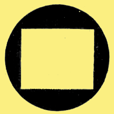
Fig. 29. - Actual photograph of screen of cathode ray tube with two-dimensional scanning (180 lines) after the manner of Fig. 28
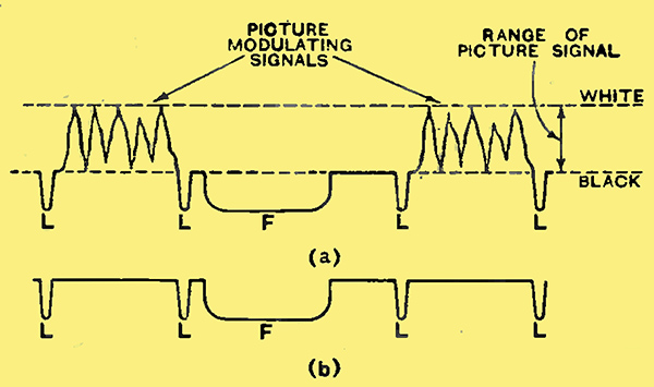
Modulating the Light Spot
Such, then, is the process of scanning, and it merely remains to vary the brightness oi the spot from point to point during this scanning process to give us complete picture reproduction. This is, of course, redone in the manner we have already considered, namely, by applying the signal voltages from our receiver to the modulating electrode of the tube.
This is the normal method of using the cathode ray tube for picture reproduction and since it depends on varying the intensity of the electron beam reaching the screen, it is usually called the 'intensity modulation' method to distinguish it from some other methods which need not be discussed here.
Synchronising
A large number of circuits, particularly those incorporating valves, now exist for obtaining a saw-tooth shape of voltage for the purpose of scanning after the manner illustrated in Fig. 28. No attempt will be made in these pages to describe them, since details will, in any case, vary with different designs for home receivers. A most important point, however, is that all these circuits have one common feature. This is their willingness to be controlled and synchronised by impulses delivered to them at exactly the correct rate. Thus in Fig. 28 very short impulses in the correct direction applied at the rate of 750 per second will keep the spot steady in its 750 per second stroke or thirty lines per picture, while pulses at 25 per second will serve a like purpose for the flyback at the end of each picture. It is also an excellent feature that these same impulses can be applied in the sense necessary to cut down the illumination of the spot and thus make it invisible during its horizontal fly-back between lines and its diagonal fly-back between pictures. The same is still true, of course, of the higher scanning speeds which will be used in the high-definition systems.
Fig. 30. - (a) Composite signal containing picture modulation and synchronising impulses - L line-synchronising; F picture-frame synchronising; (b) Synchronising impulses applied to saw-tooth generators.
This is done in practice by sending out appropriate impulses from the transmitter at the end of each line scan and in the small interval between pictures, as has already been described in connection with the scanning of a film illustrated in Fig. 20. The type of signal then received is shown in Fig. 30, consisting of picture-modulation signals, and of line-synchronising impulses (L) and picture (or framing) synchronising impulses (F) all occurring in their proper sequential order. The picture-modulating voltages are, of course, applied to the appropriate electrode of the tube, and the synchronising impulses are separated out (by relatively easy methods) and applied Io their appropriate generating circuits to control the saw-tooth voltages.
Although this may seem rather complicated in description, it is actually very simple in practice, particularly in the case of receivers designed for home use to receive a specified type of signal. The purely electrical sawtooth generating circuits are easily operated at the high frequencies involved. Moreover, they are much more easily synchronised than mechanical systems, and are noiseless in operation, having no moving parts. Their power consumption from the mains is small, indeed that of the whole cathode-ray system is small, and will not be a serious addition to the cost of running a wireless set from the mains, and that is small enough.
Transmitter Scanning
The same qualities of nimbleness and easy operation which make the cathode-ray tube so valuable at the receiver also make it equally valuable as a scanning agency at the transmitter.
Despite the vast amount of work that has been done on television, it is still true to say that scanning of direct objects or scenes is not yet in a state of development at all comparable to that which the microphone has reached in dealing with sound. The PMG Committee's Report says: 'One of the difficulties which has been encountered in direct scanning is the small amount of light available to actuate the photo-electric cell obtained by reflection from objects which are being televised'. While we will return to this subject, it is meantime safe to say that the scanning of film is very much easier and has been brought to a high level.
Since the cathode-ray tube is used in all television applications as a source of light, its function at the transmitter is exactly the same. The scanning of a film by a simple light source and mirror, rocked back and forward in a 'saw-tooth' motion, has already been described and illustrated in Fig. 20. ll then merely remains to substitute our light and rocking mirror by a cathode-ray tube and the thing is done. This is shown schematically in Fig. 31.
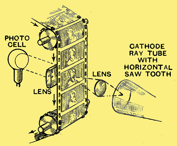
Fig. 31. - Scanning of a film for transmission by cathode ray tube (cf. Fig. 20).
The film is moved smoothly and continuously, as considered in relation to Fig. 20, while the line scanning of the film is effected by a horizontal saw-tooth motion of the electron beam, the rate of this motion depending on the number of lines in which we want to scan each frame. The light from the fluorescent screen is then swept across the film in successive lines and gives varying degrees of illumination to the photo-cell in a manner now familiar to readers.
Intermediate Film
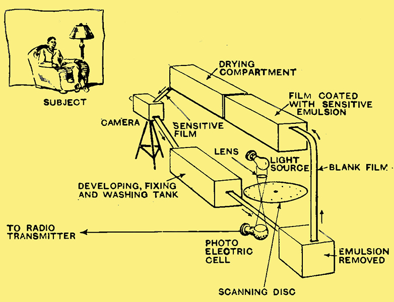
Fig. 32. - intermediate-film method of scanning.
It is clear, however, that many of the advantages of television would be completely lost if we had to depend entirely on the use of already-made films for our transmitting material. One of the most valuable features of broadcasting is the fact that it conveys things to us just as they happen, and not as they were done in Hollywood (or elsewhere) six to twelve months before. (Parenthetically, one might be allowed to exempt Mickey Mouse and Silly Symphonies from bthis category, but, since they are synthetic in any case, the argument does not hold.)
Fortunately, the solution of this difficulty is available to us in what is known as the intermediate-film method. This takes advantage of the high stage of development that cinema photography has reached and of the fact that the film can be scanned for television under favourable and controlled conditions of illumination. . The scene or object is first photographed in the ordinary cinema manner; the film is immediately developed and passed on to the television scanner. By care in design it has been found possible to develop, fix, wash, and partially dry the film within only a few seconds, and to run it through the scanner while still fairy wet.
In a recent demonstration of this method the delay between the photographic exposure and the actual television scanning was round about 20 seconds, and it is understood that even this time can be considerably shortened. The sound track is, of course, synchronised on the film and sent out as sound broadcast by this ordinary methods of sound reproduction from film. The whole story of sound and sight is thus passed on to the ether almost immediately and with a delay which need never be objectionable.
The film, once scanned, can be dried and stored, but an improvement on this method (which is understood to be in a fair stage of development) is one in which the used emulsion is wiped off, and the film re-sensitised immediately for its next exposure, as shown schematically in Fig. 32. This method also seems capable of development to give a delay of the order of 20 seconds, but it is doubtful if it will be brought into use in, at least, the early stages of the new high-definition service.
Direct Scanning
Turning to methods of direct scanning, great hope for the future also appears to lie in the cathode ray tube. The methods consist essentially of combining in one bulb the properties of the electron beam and the photoelectric cell, but two very contrasting methods of attaining this end have been devised and are in the course of technical development and improvement for service. Which of these or other methods will prove superior in actual operation is a point on which, at the moment, no useful opinion could be expressed.
On this subject the Committee regards it as bprobable that satisfactory reproduction could, even at this stage of development, be obtained of such scenes as a procession, a lawn-tennis match, or the actual finish of a horse race, though the transmission of a view of the whole course of a race, a cricket match, or a football match would present much greater difficulty'.
The two methods referred to are contrasting in that one uses a fine electron beam from a standard electron gun system and makes its pinpoint explore a square or rectangular photo-electric anode, while the other uses a photo-electric cathode, a broad electron beam and (effectively) a pinpoint anode, moving the broad beam so that the pinpoint anode explores it. Both of these devices are of American origin. The first is Zworykinbs 'Iconoscope', which seems likely to be used in the transmissions provided by the apparatus of the Marconi- EMI Company; the second is Farnsworth's 'Image-dissector', which will probably be used by the Baird Company.
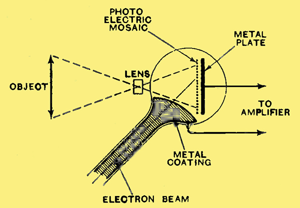
Fig. 33. - Zworykin's Iconoscope for television scanning of a direct scene.
The principle of the Iconoscope is shown in Fig. 33. An image of the scene or object to be transmitted is optically projected on to the plate which serves also as the anode of the cathode ray tube. The anode is coated with a mosaic of minute photo-electric elements, each acting as a tiny photo-cell. The cathode ray beam is swept over this plate by two saw-tooth movements, exactly as in Fig. 28, and current impulses are set up according to the varying light and shade encountered on the photo-electric mosaic.
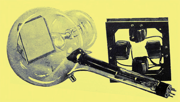
Fig. 34. - Zworykin's Iconoscope. The rectangular plate shown in the tube consists of a mosaic where each element is a miniature photo-electric cell.
An illustration of the Iconoscope is shown in Fig. 34, together with the deflecting coil system, which is placed round the neck of the bulb to apply the saw-tooth movements of the electron beam.
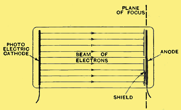
Fig. 35. - Principle of Farnsworth's photo-electric cathode ray tube (the Image-dissector).
The principle of Farnsworthbs image-dissector is illustrated in Fig. 35. An image of the scene or object to be transmitted is optically projected on to a plate which is made photo-electrically sensitive and emits electrons as the cathode of a photo-electric cell. The emission of electrons, however, varies from point to point over the surface of the plate, according to the light and shade of the image. This electron beam is adjusted to focus what can be called an 'electron image' in a plane at the other end of the tube. The method of scanning this is then effectively to move a pinpoint anode across it and pick up impulses according to its electron density from point to point.
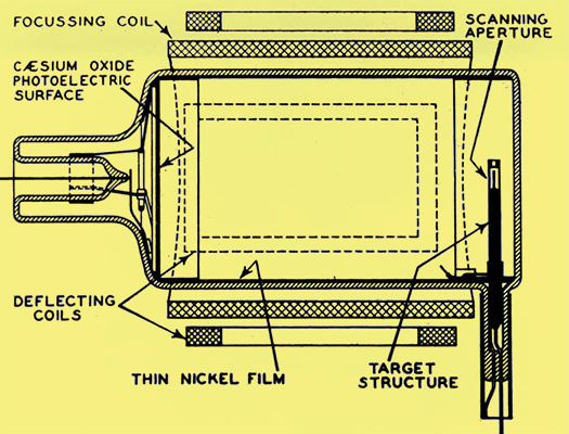
Instead of moving the anode, however, the electron beam, which is infinitely more mobile, is made to do the moving about by two saw-tooth voltages in the usual manner, so that different little elements of the broad beam shoot through a pin-point hole in a metal shield which protects the anode. A photograph of the image-dissector is shown in Fig. 36, where it is combined with an extra device described as an 'electron-multiplier', in which the phenomenon of secondary emission of electrons is used to obtain an amplifying effect which (it is claimed) can be very considerable as well as economically provided.
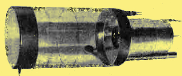
Fig. 36. - Farnsworthbs Image dissector, with its Electron Multiplier attachment.
The great utility of the cathode ray tube as a direct scanner is shown particularly in the manner in which it can be contained in an ordinary type of camera structure, such as illustrated in Fig. 37.
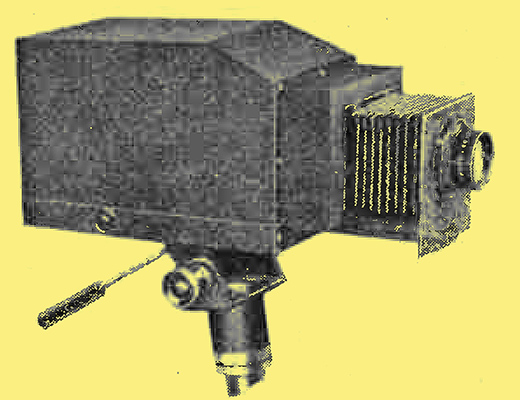
Fig. 37. - Camera containing cathode ray scanning device (Farnsworth).
This makes it extremely mobile and flexible compared with any system involving mechanical moving parts.
Need for Ultra-Short Waves
Earlier in these pages we have discussed the high-frequencies involved in the higher speeds of television scanning. It is again to be emphasised that the highest of these frequencies may not be involved all the time, but ability to deal with them when they do occur must be provided if we are to obtain the maximum resolution, particularly in moving from black to white points of the picture. In connection with Fig. 22 it was shown that it was quite impossible to accommodate within the ordinary broadcasting region the wide spread of frequency which it would be necessary to transmit and receive. It was also shown that this spread could only be accommodated in the ultra-short-wave band, such as in the region of 6 or 7 metres. This region of the ether is so far very little used, and therefore offers plenty of elbow-room for accommodation of television channels. Its use, however, is not unattended by restrictions. Without endeavouring here to enter into any discussion on the subject of propagation of radio waves, it should be remarked that our present knowledge seems to indicate a definite change in characteristics for waves below 10 metres. For one thing, these appear no longer to be reflected from the Heaviside layer, which we know to be responsible for the return to earth of those other wavelengths that give use distant reception. For another thing, it appears that to all intents and purposes they can only be received over what is practically a clear optical path from transmitter to receiver, or at least not much in excess of this distance. An improvement of optical path can, of course, be obtained by elevating the transmitter as much as possible, but clearly there are limits, economic and practical, to the extent to which this can be done. Thus a broadcast television service on such wavelengths is bound to be of a relatively local character, with a range of possibly only 25 to 30 miles, which may be less in hilly districts, unless one lives on the top of a hill. In the first place, of course, the Committee recommends the establishment of such a service for the London area only, with other districts throughout the country to be added as the service develops.
Sight-cum - Sound Broadcast
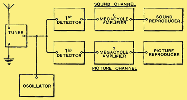
Fig. 38. - Sight-cum-sound receiver on common aerial tuned to the 6-metre band.
Both from the Report itself, and from knowledge of the general technical tendencies which one knows to have been in progress, it seems clear that the complete television broadcast will consist of the transmission of sight and sound on two adjacent wavelengths in the 6- to 7-metre band. These will be picked up on a common aerial system of sufficiently broad tuning, which will then feed what will become two separate receivers one for each of the functions. A schematic diagram of a receiver which has been developed experimentally on these lines is shown in Fig. 38. This may be taken as broadly typical of the arrangement of the home receiver for the new service. For the benefit of technically minded readers, it may be mentioned that the wavelength used in these experiments was 50 MHz (6 metres) for the sound and 49 MHz (6.122 metres) for the vision carrier. The receiver was of superheterodyne type, the common oscillator being of 55 MHz, giving intermediate frequencies of 6 MHz for the sound and 7 MHz for the picture. The intermediate-frequency amplifiers of the superheterodyne receiver were of band-pass type, the sound amplifier having a band width of about 100 kHz (since this was relatively easily achieved at these frequencies), while the sight amplifier had a band width of about 1.25 MHz. After second detector stages in each case the output passed via appropriate amplifiers to sound and picture reproducers - loud speaker and cathode-ray tube respectively. Tuning of the aerial and the oscillator was ganged, tuning to the maximum of the sound channel serving as the criterion of adjustment. It is understood, both from the literature describing these experiments and from several demonstrations of similar apparatus that have been given, that no great difficulty is experienced in the domestic operation of a suitably designed receiver working on these wavelengths.
An important practical point in connection with receiver design has also recently been raised in the technical literature describing the above experimental system. This is that the theoretical frequencies, given earlier in these pages for different scanning rates, are not confirmed on trial as being necessary for good resolution of a test picture, the nature of which, unfortunately was not stated. Thus it is argued that on a system with a frequency spread only 20% greater than that required for 180 lines, it was found possible to obtain good resolution of a 240-line picture, although a spread of twice that of 180 lines would have been demanded by theory. There are no data available to indicate whether this is generally confirmed, but the view expressed is important in showing the latitude that the eye will apparently tolerate in the matter of resolution.
The Forthcoming High-Definition Service
Such, then, is the technical position at the time of the Report of the PMG's Committee. Intensive technical development has occurred within the past twelve or eighteen months, even during the months that the Committee itself was holding its meetings. Relatively little detailed technical information has been published by the various firms concerned, but the technical notes set out in the latter part of the preceding pages give a fair although brief sketch of the facts as they are, and as they are likely to be at the time the new service starts.
It will be recalled that the Committee definitely recommends that 'a start could best be made with a service of high-definition television by the establishment of such a service in London', and it is believed that this service will be inaugurated by the latter part of this year. The BBC is to be the transmitting authority. It is also recommended that the Baird Company be given an opportunity to supply the necessary apparatus for the operation of its system at the London station and that the Marconi-EMI Company be given a similar opportunity in respect of apparatus for the operation of its system also at that station. Alternation of the two systems is recommended, but no 'frequency' of these alternations is laid down. It is demanded, however, that 'transmissions from both sets of apparatus should be capable of reception by the same type of receiver without complicated or expensive adjustment'. This is tantamount to saying that they should be completely interchangeable so far as concerns the operation of the receiver, which carries with it important technical implications.
The one essential technical fact that is laid down at present is that 'the definition should not be inferior to a standard of 240 lines and .25 pictures per second'. The arrangement and working of the service are to be left to an Advisory Committee and 'it is anticipated that a part of the Committee's work would best be carried out by a Technical Sub-Committee'.
The Report is thus broadly advisory in character, but leaves the exact details to be settled by this Sub-Committee. Nevertheless, it is a satisfactory feature that the definite specification of a television service is thus launched, with a Technical Sub-Committee to supply these details, and this arbitrary but considered specification - as has been indicated earlier in these pages - is exactly what television badly needed before progress could be made commercially.
Several important points must be settled by this Sub-Committee before the service can be begun, or, for that matter, before final details of the transmitting and receiving apparatus can be decided. These include:-
- The wavelength to be used for sound and sight respectively (thus defining the characteristics of the receiver).
- The exact type of synchronising signal to be sent out (so that the scanning circuits can be most efficiently designed).
- The number of scanning lines and the picture repetition rate (so that the scanning circuits may be arranged for easiest control by the domestic user).
It is to be assumed that in this last respect the recommendations of the main Committee will be adhered to, but the recommendation is worded with sufficient latitude to allow the Technical Sub-Committee reasonable scope.
A picture of 8 inches by 6 inches, reproduced on a cathode-ray tube, is envisaged in the Report. This, of course, must remain a matter of detail for the designer of the receiver to decide. Cathode-ray tubes capable of giving a good bright picture of this size have certainly now reached the stage of commercial production, but smaller tubes may also be featured for less expensive sets. Incidentally, it is interesting to note that the Report does not by any means restrict receiver production and sales to the firms responsible for the transmitting apparatus. Here the whole industry has a 'free field and no favour' subject to tribute to owners of patents, once the technical details mentioned above are finally settled.
Sound Technical Development Assured
It cannot be expected that low-priced receivers can be available perhaps for some long while, but even at the start prices will scarcely be prohibitive. After all, the early sound receivers were by no means cheap. It has already been said that progress in the last few months has been rapid and it is safe also to say that it is still going on. Naturally the various concerns interested are somewhat reticent on technical details, but recent demonstrations of television have revealed the real progress that has lately been made and the high entertainment value that 240-line television now offers. No greater stimulus to improvement can be imagined than that of a regular service following on lines of logical technical development, and the soundness of these lines, both for the immediate London service and for its future extension, is assured by the type of control set into operation.
The regular supply of programme material of entertainment value and the fuller development of a television programme technique must follow on a working service if public interest is to be maintained, but, after all, the same thing had to be done for broadcast sound. And so, at long last, we may be able to fulfil a one-time political prophecy - 'Wait and See'.
The following has been taken from The Story of BBC Television.
'It was like playing with clockwork when we'd already got electricity. The bloody thing just wouldn't work'. - Television producer Cecil Madden on the Baird system
In the summer of 1934, the government set up a committee, chaired by Lord Selsdon, to investigate the possibility of providing a high-definition television service to replace the low-definition 30-line transmissions already taking place. At that time Baird's improved mechanical television system had had the benefit of nearly ten years of development since its invention whilst the EMI electronic system was still in its infancy.
The picture quality of the two systems was similar, and so the Selsdon committee recommended that 'two television systems of High-Definition Television should be tried at the London Station'. The London Station was to be built and operated by the BBC, and the two systems (Baird and EMI) would broadcast on alternate weeks for a trial period of six months.
The government defined High-Definition as 'not having less than 240 lines per picture' and Baird set to work to increase his system to meet the 240 line threshold. At EMI, Isaac Shoenberg took the courageous decision to develop an electronic system which had 405 lines. This leap of faith, based on advice from his research team (over 60 strong), would have financially ruined the company had it failed.
The Baird Company set to work to design and build all the equipment for a complete television station, including the transmitters. EMI on the other hand felt that they didn't have the expertise in transmitter design, but they new a man who did - Guglielmo Marconi - so a new company, Marconi-EMI, was formed to deliver the entire electronic station.
Alexandra Palace

Alexandra Palace with TV mast in place on the East Tower.
Meanwhile the BBC, tasked with providing a suitable building complete with the studios, sound transmitter, mast and aerials - all within 18 months - began a frantic search for a suitable site. Alexandra Palace, a run-down Victorian entertainments complex in North London, was not their first choice. However it had a couple of significant advantages - one, part of it was available for rent, and two, it was on top of a hill.
The BBC knew that it was vital to get the transmitting aerials as high as possible. Calculations showed that to get a reliable range of 25 miles reception with a 34 thousand Watt transmitter; the aerial had to be about 600 feet (180 metres) above sea level. Alexandra Palace was already half that, so the transmitting tower only needed to be another 300 feet (90 metres) tall.
A year later, the building work was advanced enough for the two rival companies to start to move their equipment in. Each had their own studio and control room but shared facilities such as dressing rooms, scenery workshop and canteen. The summer of 1936 saw a hive of activity as everyone worked frantically towards the official opening date of early November - but all that was about to change.
Olympia broadcast
The 1936 Radio Show at Olympia was scheduled for the end of August. RadiOlympia was an annual exhibition put on by the Radio Manufacturers' Association, and a number of the exhibitors were displaying new television sets. Concerned that there would be no programmes to display on them at the show, the BBC came under pressure to provide demonstration transmissions during August. A variety show was quickly put together called 'Here's Looking At You', and it went out twice a day for two weeks, with the two competing television systems alternating on a daily basis.
BBC Television formally opened on 2 November 1936 at 3pm, with speeches by the Postmaster General, the Chairman of the BBC, and Lord Selsdon. The opening ceremony actually took place twice; first (on the toss of a coin) in front of the Baird cameras, and then again with the Marconi-EMI system. In this way, BBC television's second programme was also its first repeat.
The new BBC Television Service had started, and it was the first regularly scheduled true high-definition television service in the world. With the two systems alternating on a weekly basis, it was soon clear that Marconi-EMI were offering superior performance. The decision was taken to end the competition early, and after only three months the final Baird transmission went out at the end of January 1937.
The BBC 405-line television service was to continue (with a break during WWII) until the start of 1985, more than 48 years after the official start of the service.
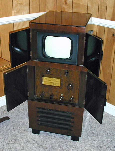
Probably the first high-definition set sold in the UK. Cossor 137T, 1936.
|