|
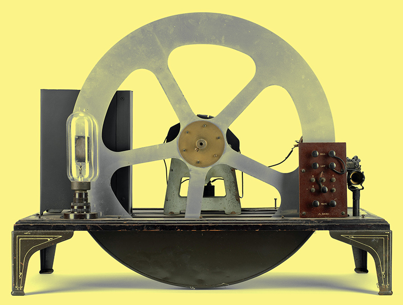
A Baird Televisor.
Television is fast approaching the stage when it can take its place in broadcasting as a companion to the familiar sound transmissions. It has not yet reached this stage, but the indications are that it will have become of entertainment value sooner than many realise. The present article is, therefore, the first of a series intended to give an introduction to the theory and practice of television, and to illustrate some of the problems involved.
1. The Principles of Scanning
The transmission and reception of moving pictures, which constitutes television, is a matter fraught with many theoretical and practical difficulties, and the art is hardly more advanced than that of wireless telephony in the pre-broadcasting era. This does not mean, however, that television is in any way impossible, and, indeed, it is at the present time possible to obtain extraordinarily good results in the laboratory. The apparatus employed, however, is too expensive and complicated for general use. The point of importance is neither the expense nor the complication of the equipment but the fact that good results are possible, for there is no doubt that development will in time result in a cheapening and a simplification of the apparatus, and high-quality television will then become a commercial possibility.
It may be said, therefore, that at long last television is becoming feasible and worth while for the amateur, and is opening out an entirely new field for the experimenter. The present tendencies in television lie in the employment of ultra-short wavelengths for transmission and the use of cathode ray tubes, at least for reception. Before the benefits conferred by these can be fully appreciated, however, it is necessary to have a full understanding of the older systems upon which the latest developments are based. Let us therefore examine the requirements.
It is well known that in the cinema the picture thrown on the screen is not actually moving. but consists really of a series of still pictures, all very slightly different from one another, and succeeding one another so rapidly that the eye is deceived, and cannot distinguish them separately. Owing to the retentivity of the eye the impression produced by one picture persists for a fraction of a second, and before it has died away the next picture comes along.
It has been found that if not less than about ten pictures a second are thrown on the screen the impression of a moving picture is produced. With such a low picture frequency, however, there is a considerable amount of flicker, and it is now the standard practice in cinemas to use about twenty-four pictures a second.
Now, in television, the same requirement holds good, and it is necessary to transmit from ten to twenty-four pictures a second. The requirements, however, are made more difficult by the fact that it is impossible to transmit even one picture instantaneously, as in the cinema. Only a minute portion of the picture can he transmitted at a time, and it is necessary to break up the picture into a large number of small pieces, transmit these one after another, and then reassemble them at the receiver. When it is remembered that the whole of this process must be carried out in from one-tenth to one-twenty-fourth of a second, some idea of the speeds involved can be gained.
The Photo Cell
The variations in light intensity in the picture are converted into variations of an electrical current with the aid of a photo-cell. Such a cell is analogous to a valve in that the light falling upon it varies a steady current through the cell in the same way that a change of grid voltage in a valve varies the steady anode current. Provided that the cell is correctly operated the change in output current is proportional to the change in light intensity, so that we have available a distortionless method of converting variations of light into variations of current which are electrically equivalent to an alternating current superimposed upon a direct current, just as in the output of any ordinary valve.
It will be obvious that if we focused the whole picture to be transmitted upon the photo-cell the current through the cell would change by an amount depending upon the total illumination of the picture, and would not depend at all upon, the details of the picture. If we break the picture up into quarters, however, and let the light from each quarter fall upon the cell successively, we shall obtain a different value of photo-cell current for each quarter depending upon the total illumination of each quarter. We shall still be far from perfect, and shall obtain no intelligible picture, but the results will represent an advance on those obtained by focusing the whole picture upon the cell. Following the same argument, it will be seen that if we break the picture up into an infinite number of elements and let the light from each fall successively upon the cell, we shall obtain electrical variations of current which constitute a complete copy in the different medium of every detail of the picture.
A Method of Scanning
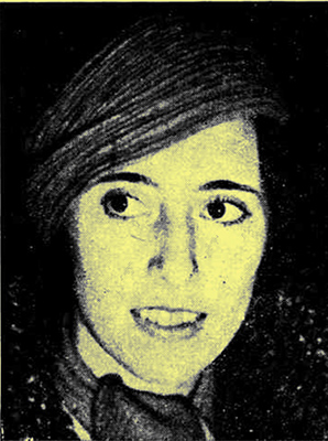  
(a) In making this picture a block with a normal screen has been used.
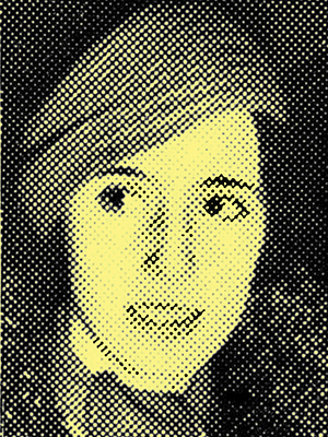
(b) In this picture a coarse screen has been employed with the result that much of the detail has been lost.
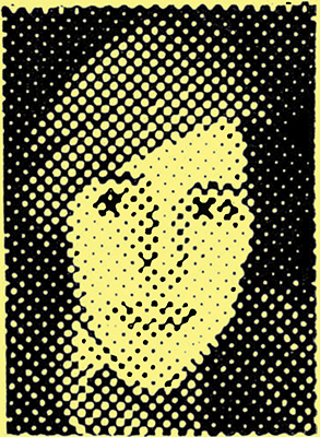
(c) Here the screen is so coarse that little resemblance to the original picture can be seen at first, but if examined from some distance the definition apparently improves.
All printed pictures are made in a similar way from an extremely large number of elements, and if any half-tone illustration be examined under a magnifying glass it will be seen to consist of a large number of minute dots, and the greater the number of dots to the inch the better the picture. This is well brought out by the illustration, which shows the same picture printed with different numbers of dots to the inch, or different screens. At (a) a normal screen of about 85 dots per inch is used, whereas at (b) a much coarser screen has been employed. The picture shown at (c) is still coarser. and it is instructive to note how much detail has been lost. If the pictures be regarded from a distance, however, the differences appear far less, and the worst picture becomes intelligible.
The dot analogy is not strictly accurate in television, for the picture is normally broken up into a series of lines rather than distinct dots. The underlying principle, however, is the same, and the differences are brought about chiefly by the methods involved. The process of breaking the picture up at the transmitter and reconstituting it at the receiver is called scanning, and in its simplest form this is carried out by means of a Nipkow disc.
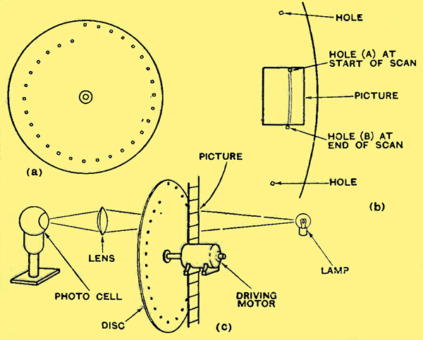
Fig. 1. - The scanning mechanism employed in simple television apparatus is shown diagrammatically. At (a) the arrangement of holes in the Nipkow disc can be seen, and (b) shows how the picture is traced by the successive holes. The complete arrangement for transmitting a picture from a cinema film is illustrated at (c).
This consists of a rotating disc (Fig. 1a) with a number of holes in the form of a spiral. The picture is enclosed by a frame so arranged that only one hole at a time can be opposite it, as shown in Fig. 1b. The number of holes is equal to the number of scanning lines required, and the number of holes multiplied by their width must equal the width of the picture. The distance between the holes round the circumference of the disc is equal to the height of the picture. It will be seen, therefore, from Fig. 1b, that at the instant that hole (B) finishes its traverse of the picture, assuming the disc to he rotating in a clockwise direction, the hole (A) is just coming on to the picture, and will traverse a path immediately adjacent to it.
A set-up which could he used for transmitting a cinema film is shown in Fig 1c, where the light from a lamp is directed through the film, and after being scanned by the disc falls upon the photo-cell.
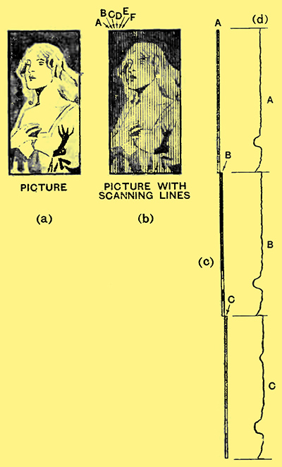
Fig. 2. - The picture to be transmitted is shown at (a), and at (b) the effect of scanning can be seen. The strip (A) is first scanned and then (B), so that in regard to time the picture is broken up into a long strip (c) and the photo-cell current varies as shown at (d).
This process is illustrated in Fig. 2, in which the original picture is seen at (a); (b) shows the scanning strips into which it is divided, and (c) shows the sequence of these strips from the point of view of time. At (d) will be seen the corresponding electrical current in the photo-cell circuit, the variations of current during the interval (A) corresponding to the variations in light intensity along the strip (A) and so on.
It will be obvious that the narrower the width of the scanning strips the greater will be the picture detail, for, assuming a square hole in the disc, the smaller will be the average illumination at any given instant. In other words, the greater will be the number of elements, or, in terms of half-tone illustrations, the finer will be the screen. In the present BBC. transmissions by the Baird process 30 lines are used and 12½ pictures are transmitted a second. There are thus 375 lines transmitted a second.
It will be readily apparent that the breaking of the picture into such a small number of lines must lead to a poor quality image at the receiver, but before considering the number of lines which is necessary for a good picture, it will be as well to examine the other details of the transmitter and receiver.
2. The Transmitter and Receiver
Above it was shown how the picture to be televised is converted into a series of strips and the light variations along these made to produce a varying current in a photo-cell. Although this current is strictly speaking uni-directional, it may be considered as being an alternating current superimposed upon a steady direct current, just as we make the same assumption in the case of the anode current of any valve. The photo-cell output, therefore, can be considered as an alternating current, which is strictly analogous to the current output of a microphone used in sound transmission.
The photo-cell output can thus he treated in exactly the same way as the output of a microphone; it is amplified to the requisite degree, and then used to modulate the carrier of the transmitter. Such differences as may occur in practice are due merely to the different frequencies involved in television as compared with sound broadcasting. Instead of the range of modulation frequencies being from 30 to 10 kHz, in the case of television it may be from 12½ to 300 kHz or more, depending upon the precise details of the television equipment.
In the receiver there is again no difference, apart from the different range of modulation frequencies involved. HF amplification, detection, and LF amplification are all necessary and follow standard practice. In fact, the equipment necessary for television is fundamentally the same as that used for sound broadcasting, save that at the transmitter suitable optical apparatus and the photo-cell replace the microphone, and at the receiver a light source and optical apparatus replace the loud speaker. For the present, therefore, we need not consider the electrical circuits of transmitter and receiver, and we can turn directly to the television 'loud speaker'.
Primarily, this consists of a light source of such nature that the light intensity is proportional to the operating current, and which is capable of responding instantaneously to rapid variations in the current. This last requirement rules out all ordinary lamps, and it is usual to employ a neon tube, although other and more efficient methods have been developed. The lamp is commonly connected in the anode circuit of the output valve of the receiver, and the steady anode current passes through it. In the absence of a signal, therefore, the lamp gives out a steady light the intensity of which depends upon the value of the anode current, and which can be controlled by varying the anode current.
The Scanning Disc
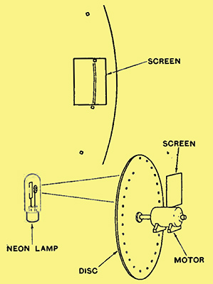
The upper portion of this drawing shows the manner in which the holes in the scanning disc pass over the viewing screen, while the lower portion illustrates the arrangement of the apparatus. The light from the neon tube passes through the holes in the disc and falls on the screen. The position of the spot of light at any instant is determined by the precise position of the disc.
The television signal causes fluctuations in this steady current, and the light then varies in sympathy. If we look directly at the lamp, therefore, we can see all the light variations of the transmitted picture, but they do not form any intelligible picture because the picture has been broken up into a series of strips at the transmitter, and it is necessary to reassemble these at the receiver.
This is carried out by means of a Nipkow disc, the whole process being exactly the reverse of that at the transmitter. The disc is interposed between the viewing screen and the neon tube, as shown above, and matters are arranged so that the light from the tube can fall upon the screen through only one hole at a time. The disc must be identical with that used at the transmitter, and it must rotate at exactly the same speed ; furthermore, at the instant when any one hole is just commencing to scan the picture, the corresponding hole at the transmitter must also be just commencing to scan the picture. In this way the strips into which the picture was broken at the transmitter are reconstituted in their correct relative positions at the receiver, and the picture can be seen on the screen.
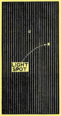
Fig. 4. - At any instant the picture consists of no more than a single minute spot of light, but, owing to the retentivity of the eye, the movements of this cannot be distinguished, and the effect of a steady picture is obtained.
It will be seen that the difficulties involved are two-the attainment of exact synchronisation of the discs, and obtaining sufficient illumination. Taking the latter first: in a cinema, if there are ten pictures a second, each picture is fully illuminated for rather less than one-tenth of a second. The televised picture, however, for the same picture frequency, requires a much stronger light source for the same illumination, for at any instant there is only one small spot of light on the screen. This will be seen from Fig. 4, which illustrates the traverse of the light spot at the receiver. This small spot covers the whole picture in one-tenth of a second, and consequently it must be of extraordinary brilliance if the whole picture is to appear in any detail.
A concrete example may serve to emphasise the importance of this point. Assuming for simplicity that there are ten pictures a second in a cinema, each picture is completely illuminated for a twentieth of a second, if the interval between successive pictures is equal to the duration of each picture. With television equipment there is no interval, but the area of the light spot is only about 1/2,000 of the picture area, so that any given portion is illuminated for only 1/20,000 of a second. The increase in illumination required, therefore, will be readily apparent.
It is on the score of brilliance that the neon tube is apt to fail as a light source in a television receiver, but nevertheless it is possible to obtain quite good results with it, although there are now better methods available. The chief difficulty lies in synchronising, for the degree of accuracy required is so high as to necessitate a definite linking of the transmitter and receiver. Synchronising is really a whole subject in itself, and it will be dealt with next.
The Problem of Synchronisation
It might be thought that satisfactory synchronisation of the Nipkow discs at the transmitter and receiver could be obtained by the simple process of using identical motors and adjusting them to run at the same speed, by controlling the receiver motor by means of a variable resistance or some similar device. It might be thought also that the mechanism of a clock could be pressed into service, for it is one of the most accurate pieces of mechanism in common use. One which gains or loses a minute a week is considered to be only a fair timekeeper, and yet this represents an accuracy of 0.0154%. The degree of accuracy necessary in the synchronisation of the discs for television purposes may perhaps be realised when it is remembered that it corresponds to a clock which gains or loses no more than one second in several months.
Where 12½ pictures are transmitted a second, and there are 30 lines to a picture, the disc must rotate 750 times a minute. Many methods of synchronisation have been proposed, but that now used in the BBC, transmissions is quite simple. The transmitted picture is arranged to have a black strip along the top, with the result that at the beginning of each scanning line there is a sudden pulse of current in the photo-cell circuit, and this leads to a similar black strip along the top of the received picture. One pulse of current per line means 375 pulses a second. and by means of suitable filters they can be picked out of the picture currents proper and applied to a motor on the shaft of the receiving disc. The power available. of course, is quite insufficient to drive the disc, so that this is run by an electric motor, the speed of which is regulated by the synchronising impulses.
The Synchronising Impulses
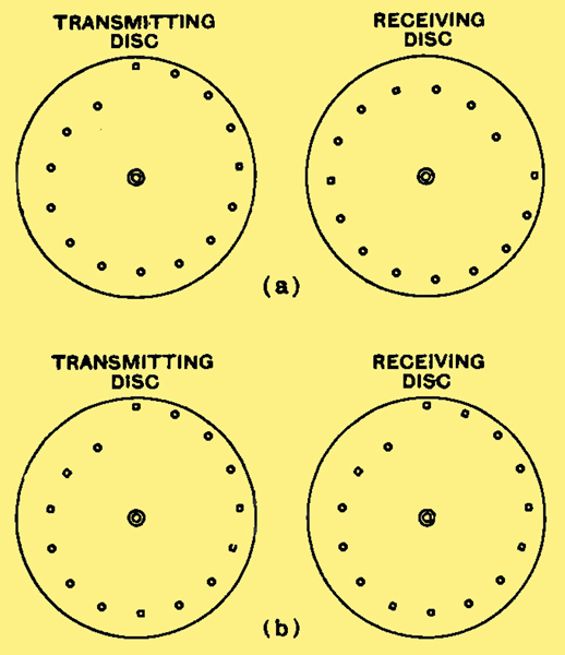
Fig. 5. - When both transmitter and receiver discs are rotating at the same speed, synchronism is obtained although the holes may not be in the same relative positions. Isochronism requires that the hole positions be in the same positions as in the left hand drawing.
This is carried out by an arrangement such as a phonic wheel, which is really a. miniature electric motor mounted on the same shaft as the main driving motor. The phonic wheel, or similar device, is fed by the 375 cycles synchronising impulses, and receives one impulse at the start of every scanning line. If the driving motor is running too quickly the synchronising impulses are received by the controlling motor too late, and it exercises a breaking effect upon the disc and retards its speed. If the motor is running too slowly an accelerating effect is produced. The result is that within limits the 375 cycles pulses maintain the transmitter and receiver discs in isochronism, that is, they run at exactly the same speed.
Although they may run at the same speed, they are not necessary in synchronism, for this involves a question of phase. The discs are in isochronism if they are running at the same speed, but if one be displaced relatively to the other in an angular direction they are not in synchronism. Exact synchronism is only obtained when the discs are running at the same speed and their holes are in identical relative positions at all times. Thus, in Fig. 5 the two discs at (a) are in isochronism when they are running at the same speed, but, since the holes are not in the same relative positions, they are not in synchronism. True synchronism is shown at (b), where at every instant the holes in the receiving disc correspond exactly with those in the transmitting disc.
In practice, true synchronising is obtained by trial and error. The synchronising impulses enable isochronism to be readily established, and the picture can then be seen, even if the holes in the discs do not correspond. Unless perfect synchronisation is obtained, however, the picture will be divided with the left-hand half on the right-hand side of the screen, and vice versa. It is a simple matter, therefore, to retard the motor momentarily until it is in exact synchronisation.
The Requirements for a Good Image
The fundamental methods of television transmission and reception have been explained above. Now with some knowledge of how the apparatus functions we can now consider the requirements for good results. There are two things which we must first decide - the picture frequency and the number of scanning lines. The greater the number of pictures transmitted a second the less likely we are to be troubled by flicker, and cinema practice tells us that we need not go above about twenty-four pictures a second for practically perfect results. The greater the number of scanning lines used the better will be the definition and detail.
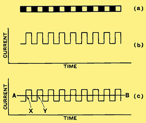
Fig 6. A series of black and white squares (a) gives rise to a photo-cell current of the type shown at (b). This is equivalent to a direct current, represented by AB in (c), with a superimposed alternating current.
Now the higher the picture frequency and the more lines used the higher will be the modulation frequencies required in the transmitter and the greater will be its sideband spread. It is here that the greatest practical difficulty is to be found, and so the first step is to determine the highest frequency required. Let us suppose that we wish to transmit a chessboard in which the black and white squares are the same size as the hole in the scanning disc or its equivalent. The variations in light and shade for a single scanning line are shown at (a) in Fig. 6, and the corresponding photo-cell current at (h). In this particular case eighteen squares are shown of which nine are black and nine are white. There are, therefore, eighteen changes in the value of current through the cell. This current, however, may he regarded as an alternating current superimposed upon a steady direct current, as shown at (e), in which the line AB represents the steady current for this type of picture. It will he seen that one complete alternation of current occupies the time from X to Y, and for eighteen squares there are nine such alternations.
Maximum Modulation Frequency
A telephony transmitter of roughly equal quality would require a total sideband spread of no more than 20,000 Hz, so that a single television transmitter would occupy as much space in the ether as 375 telephony transmitters. Moreover, transmission could not be carried out at all on frequencies below 3,750,000 cycles, or wavelengths above 80 metres.
In practice, the highest frequency required is not so readily calculated, for the picture is not divided into a definite number of elements as in the case of a half-tone block. The maximum frequency is dependent upon the maximum rate of change of light, and this in turn depends upon the type of picture being transmitted. If the picture contains strong black and white contrast with a sharp dividing line, the frequencies needed will be higher than if it is delicately shaded with the whites merging gradually into the blacks.
Present Transmissions
The chessboard pattern which we have assumed is one requiring the highest frequencies, and represents the worst possible case. Even so, the frequencies required are likely to be as much as three times those calculated above on account of the presence of a strong third harmonic in the photo-cell current.
The present BBC transmissions fall far below this ideal, of course, for there are only 30 lines and 12½ pictures a second. The ratio of height to breadth of the picture is 7:3, so that if we take the condition of the transmission of at chessboard 70 squares in height by 30 squares in width, the fundamental maximum frequency will be 12½ × 70 × 30/2= 14,100 Hz. It is believed that the maximum frequency transmitted at present is in the neighbourhood of 13,000 Hz. It is evident, therefore, that the present transmissions could just deal with a chessboard of the type described, provided that the photo-cell current involved no harmonics. As the current will always include harmonics, they will be absent in the receiver and the image will not show the sharp dividing lines between the squares which are characteristic of a chessboard, but the white and black squares will merge into one another through shaded areas.
One would expect, therefore, on these theoretical grounds that the present transmissions would be of little practical value. This is not so, however, for the reason that as severe a test as a chessboard rarely occurs in practice. Whatever the area of the objects involved, a sudden change from black to white necessitates equally high frequencies, but as in the practical case these sudden changes occur less frequently, the defects are correspondingly less noticeable.
A Practical Compromise
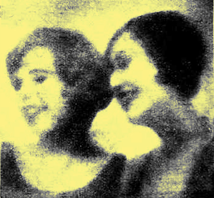
The fact that the photo-cell current does not change instantaneously leads to a blurring of the received image which is accentuated by a loss of extremely high frequencies. This is well brought out in this illustration.
At the present time perfection appears almost impossible, and it is necessary to decide the maximum modulation frequency that can be used in practice and the minimum frequency which will give an acceptable performance with real entertainment value. This is hardly a matter which can be decided at present, but the writer has seen pictures with a ratio of height to breadth of 5:6 transmitted with a picture frequency of 25 and with 120 lines, and in his opinion there can be no doubt of the entertainment value of such an arrangement. The results are far from perfection, of course, but they are so good that it is easily possible to forget that the picture is televised and to lose oneself in the programme. A system of this nature involves frequencies of 25 × 144 × 120/2 = 126,000 Hz, and, taking into account the inevitable harmonics, frequencies up to 300 kHz are needed.
The lowest frequency required is a matter of some importance, but in general this need not be below the picture frequency. With the BBC transmissions, therefore, the receiver must operate over the range of 12½ to 13,000 Hz, and with the really high quality system from 25 Hz to 300,000 Hz.
It will be immediately apparent that the design of a low-frequency amplifier to cover the latter-range is a matter of no little difficulty, particularly as phase distortion is a matter of some importance. LF transformers, of course, are ruled out, and it is usual to employ resistance-capacity coupling modified by the inclusion of corrective networks to compensate for the inevitable high note loss due to stray capacities.
In transmission, however, the presence of modulation frequencies up to 300,000 Hz leads to difficulties owing to the sideband spread of the transmitter, for a single station will occupy as much space as sixty present-day broadcasting stations. It is apparent, therefore, that television transmitters of this type can only work on the ultra-short wavelengths around 5 metres; there is no room for them anywhere else.
It is probably this question of the high modulation frequencies involved that has limited the growth of television more than anything else. High quality television will not appear until the technique of transmission and reception on 5 metres is more fully developed.
Mechanical Scanning Systems
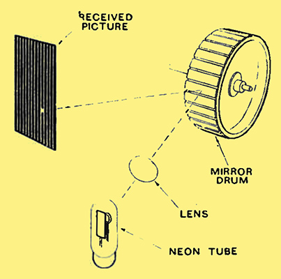
Fig. 7. - Mirror drum apparatus is here depicted diagrammatically. The drum rotates at high speed and each mirror is set at a slightly different angle.
The action of the simplest form of mechanical scanning, the Nipkow disc, has already been dealt with; there are, however, many alternatives which find considerable use in modern television equipment. Undoubtedly, the chief of these is the mirror-drum. The Nipkow disc is replaced at transmitter or receiver, or both, by a drum the periphery of which carries a series of small mirrors; there is one mirror for every scanning line required, and the mirrors are all identical save for their angle of attachment to the drum.
The arrangement of the receiver is depicted in Fig. 7. The light from the neon tube passes through an optical system for focusing purposes and falls upon one of the mirrors on the drum. It is then reflected on to the viewing screen, and it will be readily appreciated that the precise point on the screen upon which it falls will depend upon the precise angle of the mirror in two planes. The position of the spot on the screen in a horizontal direction depends upon the angle of the mirror relative to the axis of the drum, assuming the neon tube and screen to be correctly placed. The vertical position, however, depends upon the angular displacement of the mirror around the circumference of the drum.
The drum is rotating, so that the spot of light moves across the screen in a vertical direction. If the angle of each mirror were made the same, the result would be the appearance of a single vertical line of light upon the viewing screen. Each mirror, however, is mounted at a slightly different angle, so that the light reflected from the first causes the light spot to traverse a line at the extreme edge of the screen, the light from the second mirror a line immediately adjacent to this, and so on, until the last mirror gives rise to a line at the other edge of the screen. The whole process is then repeated.
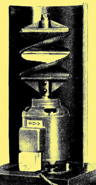
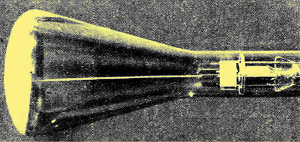
The Te-Ka-De mirror screw employed in Germany.
The process achieves the same result as the Nipkow disc, and it has the merit of greater optical efficiency, provided that suitable mirrors are used. There are many variations in practice, and the drum does not necessarily take the form shown in Fig. 7. This is the usual form, certainly, but a modification has been derived in Germany which has the merit of occupying far less space. It is usually known as the mirror screw, and its operation will be seen from the photograph above, which is self-explanatory when it is remembered that the screw is rotating about its axis, and that the scanning is carried out horizontally in accordance with the usual practice outside the British Isles.
Vibrating Mirror System
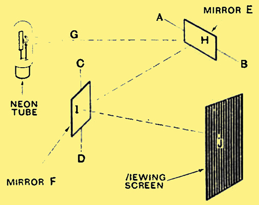
Fig. 8. - A system of scanning involving vibrating mirrors. The action is explained in the text.
Other arrangements of mirrors have been tried out, of which the most important is perhaps that employing oscillating mirrors instead of rotating arrangements. This is shown in Fig. 8, and it will be seen that the mirror E oscillates rapidly about its axis AB, while the mirror F oscillates slowly about an axis CD at right angles to that of the former. The beam of light GH from the neon tube falls upon the mirror E and is reflected from it along the line HI. Now, the angle between GH and HI depends upon the angle between GH and the surface of the mirror, and is just double the latter angle. Since the mirror is oscillating, the angle between GH and HI is continually altering, and the result is to cause the point I where the beam HI impinges upon the surface of the mirror F to move in a vertical direction.
This mirror F, however, is also oscillating about the axis CD, so that the angle between HI and IJ is changing. The result of the oscillations of both mirrors is to cause the spot of light on the viewing screen to move both vertically and horizontally. The oscillation of mirror E makes the spot move vertically, and that of mirror F gives a horizontal deflection. The oscillation of the former, therefore, is rapid, and gives the scanning lines, while the slowed oscillation of mirror F results in successive lines being correctly displaced sideways.
So far, this system has not proved of great service, for synchronisation of the oscillation frequencies of the mirrors proves far more difficult than in the case of a simple rotating disc or drum. From a theoretical standpoint, however, it is undoubtedly attractive.
Mechanical Difficulties
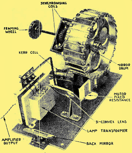
The arrangement of parts in mirror drum equipment. In this particular case a Kerr cell is used, to modulate a source of light, instead of a neon tube.
With the present 30-lines transmissions mechanical methods of reception can be entirely satisfactory, but it is doubtful whether they can provide the necessary accuracy for the domestic reception of higher grade pictures. Assuming that some form of rotating mirror drum be used, an increase in the number of scanning lines means an increase in the size of the drum. This, in turn, means increased weight, which carries with it the necessity for a more powerful driving motor and greater difficulty of synchronisation. An increase in the number of pictures a second, which is also desirable, means an increase in the speed of rotation of the drum, which introduces further difficulties. It is, of course, quite possible to use a mirror-drum for 120-line transmissions with twenty-five pictures a second, and good quality pictures have been transmitted in this way. Although these pictures could doubtless be received with the aid of a similar drum, its dimensions and the type of motor required to drive it are unlikely to commend themselves for domestic reception, and it is the usual practice, therefore, to abandon mechanical methods for high-quality picture reception, although they may still be employed in transmission. The cathode-ray tube is becoming more and more applied to television reception, and it appears likely to displace mechanical methods entirely.
Apart from the space required to accommodate the mirror drum and its driving motor, it is a matter of considerable difficulty to obtain completely silent operation, and the whine of the motor can become troublesome. Moreover, cabinet work has to be extremely rigid if the vibration is not to affect the operation. None of these difficulties is apparent with the cathode-ray system, for the arrangement is entirely electrical. The questions involved, therefore, will be considered in some detail next.
The Cathode-ray Tube
A cathode-ray tube in which the beam of electrons can clearly be seen.
There a two general systems whereby the cathode-ray tube may be used for television reception; one involves a special type of transmission, but has the advantage of involving no synchronising difficulties in the receiver; the other can be used for the reception of any mechanical scanned transmission, but necessitates careful attention to synchronisation if successful results are to be obtained. Taking the latter first, let us consider the requirements for successful operation.
The principles of the cathode-ray tube have recently been described in The Wireless World and it is unnecessary to go into any detail. It will suffice to say that a beam of electrons is emitted by the cathode, and, on striking a fluorescent screen mounted on the end of the tube, gives rise to a spot of light. The intensity of the spot of light is dependent upon the density of the electron beam, and means can be provided for controlling this, The position of the spot of light can be varied at will by deflecting the electron beam by applying suitable potentials to pairs of plates set at right angles at a suitable point in the tube.
By applying a suitable type of voltage to one pair of plates, the light spot can be made to move sideways and give the effect of a line of light. the application of another suitable voltage to the other pair of plates will cause the light spot to move vertically. By the choice of the correct frequencies, waveform, and amplitude for these voltages the light spot can be made to move over the screen in any desired manner. For the reception of vertically scanned transmissions, such as the present BBC, the light spot is made to move vertically 375 times a second, and horizontally 12½ times a second.
One difficulty which will be obvious with this arrangement is that when the spot of light has moved to the bottom of the screen it must return to the top before the next scanning line can start. If it took as long to return to the top as to travel from the top to the bottom it is obvious that with normal methods of transmission no intelligible picture would be obtained for alternate lines would be upside down. The waveform applied to the deflecting plates, therefore, is of a special type, so that during the scanning cycles the light spot moves steadily clown the screen, but, having reached the bottom, it returns the top for the next line much more rapidly. The time taken for the return upward movement of the spot is negligible in comparison with that required for the downward movement. ln the horizontal movement for the separation of the scanning lines the same quick return is obtained.
The Synchronising Voltages
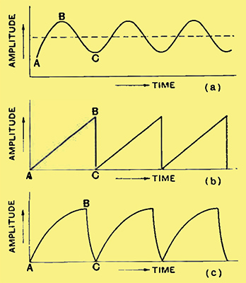
Fig. 9. The various types of waveform which might be used for the voltages applied to the deflecting plates are illustrated here. A saw-tooth waveform as at (b) is desirable.
The apparatus additional to the cathode-ray tube, therefore, must provide suitable deflecting voltages, and ensure that they are in synchronism with the synchronising impulses in the transmitter. A special form of oscillator is required, therefore, for the ordinary oscillator gives an output which, in the absence of harmonics, is a sine wave, as shown in Fig. 9a. Suppose we try using an oscillator of this nature, however, Considering the lowest portion of the negative half-cycles to represent the zero line, the voltage rises slowly at first from the point A, then rapidly, and again slows down as it is approaching the point B. After passing this point it commences to fall, slowly at first, then more rapidly, and then slowly again as it approaches the minimum C.
The light spot on the viewing screen will follow these variations. The scanning stroke is between A and B, and the speed of the light spot will obviously vary during the line; moreover, the return stroke is the interval BC, which is equal to the scanning stroke. obviously this will be unsatisfactory.
Let us consider, therefore, what is actually required. During the scanning stroke we need a voltage which rises steadily until the line has been completed, and which then falls instantaneously to zero to permit the light spot to return for the next line. The voltage required, therefore, takes the form shown in Fig. 9b in which the interval AB represents the scanning stroke, and BC the return stroke. In practice, of course, it may prove impossible to obtain exactly this waveform. but it is by no means difficult to generate a voltage which closely approaches it, but which is actually of the form shown greatly exaggerate in Fig. 9c.
The methods of generating such a voltage are more complicate than those for the usual sine wave, but there is nothing essentially difficult about them. In general, the rise in voltage along AB is obtained through the charging of a capacitor through a constant current device such as a saturated diode or a screen-grid valve or pentode, while the sudden drop along BC is obtained by suddenly discharging the capacitor with the aid of a neon tube, a thyratron, or an over biased valve.
The frequency of oscillation is determined by the effective resistance and capacity of the circuits, and can be varied by changing either. It is, therefore, quite possible to produce oscillators the frequencies of which can be readily controlled by variable capacitors or resistances. The cathode-ray tube, therefore, offers the important advantage over mechanical systems that it is readily adaptable to the reception of signals with any scanning or picture frequencies, for the oscillator frequencies can be easily adjusted to suit the transmission, whereas with a mechanical system it is necessary to fit at least a new drum or disc. A change from horizontal to vertical scanning at the transmitter requires only a change-over in the frequencies of the two oscillators with the cathode-ray system, but it would necessitate the complete rebuilding of the receiver with a mechanical arrangement. As most foreign stations use horizontal scanning, and the present British transmissions are vertically scanned, this is not without importance.
Synchronisation is dependent upon the maintenance of the two oscillators at exactly their correct frequencies, and in practice this is usually obtained by feeding them with the synchronising impulses carried by the television signal. These impulses increase the oscillator potential momentarily when it is approaching the point B (Fig. 9), and ensure the breakdown of the discharging device at the correct instant.
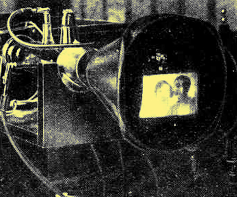
The manner in which the picture appears on the end of the cathode-ray tube is well brought out in this illustration.
There are, of course, certain difficulties in the way of good cathode-ray television reception among which synchronisation is one of the foremost. Another point which must not be forgotten is that the variations in intensity of the electron beam, which are required for the variations of light and shade in the picture, affect the focusing of the beam to some extent, and may possibly affect its position on the screen. All this means distortion and a reduction of detail, so that an alternative system which requires neither synchronisation nor modulation of the electron beam is of considerable interest, and will be dealt with next.
Variable Speed Scanning
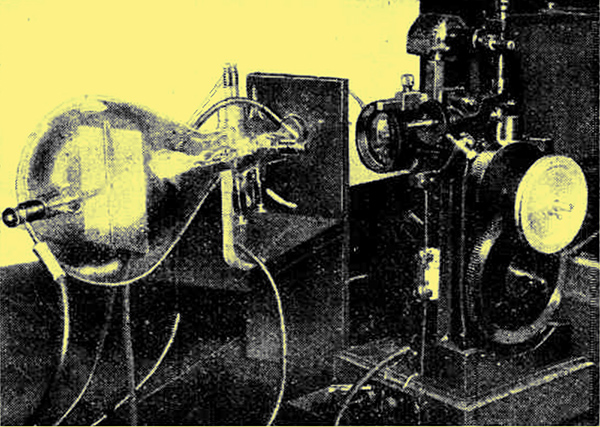
This photograph shows some of the experimental gear employed for television by the variable-speed scanning system.
The usual cathode ray television receiver can be used for the reception of all ordinary kinds of transmissions, whether they are effected by cathode ray tubes, Nipkow discs, or mirror drums. The receiving tube, in fact, merely performs in a different manner the functions carried out by a modulated light source and a mechanical scanning system. An alternative arrangement, however, is possible, and it is one which is not based in any way upon mechanical methods and which involves the use of cathode ray tubes at both transmitter and receiver. The tubes, moreover, can be of simpler construction than those normally used for television purposes, since a means of controlling the density of the electron beam is unnecessary. In the construction of the tube, therefore, the electrodes for modulating the electron beam can be omitted.
The system is due to Von Ardenne and is usually known as variable speed scanning; instead of the light spot traversing the screen at a steady rate to build up the scanning lines, its speed depends upon the light and shade in the picture. At first sight, the system appears complicated, and there are undoubtedly practical difficulties in the way of obtaining satisfactory results at the transmitting end. The basic theory, however, is delightfully simple, as is also the receiving equipment.
Brilliancy v Speed
Suppose we set up a cathode ray tube and apply a saw-tooth waveform to one set of deflecting plates only. A single line of light will appear on the viewing screen, and we may enquire what governs the brilliancy of this line. Apart from factors such as the screen material, the construction of the tube, and its operating voltages, which for our present purposes we may take as constants, the important point is the speed at which the spot of light traverses the screen to produce the visible effect of a line through the retentivity of the eye. Provided that the speed of repetition is not so slow that the building up of the line becomes visible, the slower the speed of traverse, the more brilliant will the line appear. This carries with it also the assumption that the number of repetitions remains constant, which means that under certain circumstances the operating voltage on the plates of the cathode ray tube may not assume a true saw-tooth waveform.
It is of great importance fully to appreciate this point, so that it will be well to consider it in somewhat greater detail. Suppose that the spot of light is moving down the viewing screen 15 times a second. The deflecting plates of the tube have applied to them a true saw-tooth waveform in which the potential rises steadily to its maximum value and then drops instantly to zero, so that the spot of light moves steadily across the screen, and having completed one line immediately drops hack to its starting point ready for the next line. This condition is then the same as for ordinary cathode ray television scanning, save that in practice, another voltage is applied to the other set of deflecting plates to spread the lines out to form a picture and the frequencies are higher than we are here assuming.
Suppose now that we arrange matters so that the spot of light traverses the line more rapidly, and having completed a line, let it drop back ready for the next line as before. Instead of letting it commence the next line immediately, however, let us so arrange matters that an interval elapses equal to the difference of time of the two speeds of traverse. Whatever the actual speed of traverse, therefore, there will he exactly the same number of lines a second, but the higher the speed, the smaller will be the time during which the spot of light is actually traversing the picture. Obviously, therefore. the higher the speed, the less visible will be the line
The Scanning System
This is the principle adopted in variable speed scanning. The light and shade in the picture is reproduced, not by variations in the intensity of the electron beam, but by variations in its speed of traverse.. Over a dark portion of the picture the beam moves rapidly, but over the light parts much more slowly. It will be obvious, therefore, that in an uncontrolled system of this nature the number of pictures a second becomes a very variable quantity. Should the picture predominate in light patches, the cathode ray beam moves more slowly than if it he largely dark, and a longer time is required for the complete traverse of the whole picture. Thus, there will be fewer pictures a second with a light object than with a dark.
In order to avoid this, it is usual to arrange matters so that the normal time for a single scanning line is that for a white object. The usual line is darker than this, so that means are included to stop the beam at the end of the line and make it wait until the correct time has elapsed before starting the next line. In other words, a definite time interval is assigned to each line, and if the picture be such that the beam has scanned a line in a shorter interval, it must wait before it starts on the next line. In this way the number of scanning lines and pictures a second is maintained constant as with ordinary cathode ray television methods.
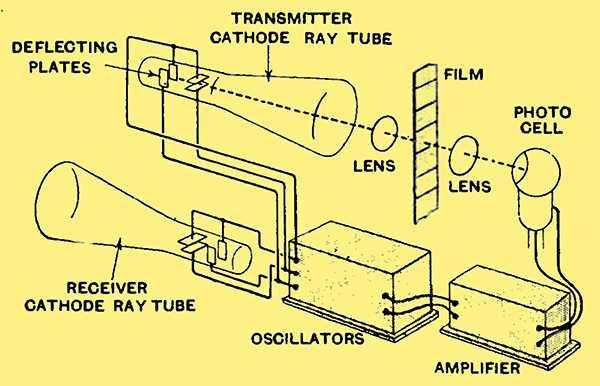
Fig. 10. - The details of the variable-speed scanning system are illustrated here. The receiving tube is shown as connected by wires to the transmitting apparatus; actually, of course, a radio link can be interposed..
One arrangement for achieving this form of television is illustrated diagrammatically in Fig. -10. The beam from the transmitting tube is focused on to a photocell or its equivalent, passing through at cinema film on its way. The oscillator's provide voltages to the deflecting plates which cause it to describe a series of lines, just as in the case of an ordinary transmitter. If we now took the photo-cell current and applied it to the modulating electrode of a television type cathode ray tube, to the deflecting electrodes of which the synchronising voltages were applied, we should have an ordinary cathode ray television.
Instead of doing this, however, the output of the photo-cell is applied to the oscillators controlling the deflection of the cathode ray beam. After suitable amplification, matters can be so arranged that a reduction in photo-cell current causes an increased voltage to be applied to the deflecting plates, so that when a dark portion of the picture passes in front of the beam. the speed of the latter is accelerated.
If we parallel the deflecting plates of the transmitting tube with those of an ordinary cathode ray tube fitted with a fluorescent screen, therefore, the beam in the latter will vary in exact accordance with that of the transmitter, and the picture will appear on the screen. It will be observed that two sets of deflecting voltages are required. but as they are of widely differing frequencies, they can be carried by a single pair of wires, and separated at the receiving end by suitable filters. Alternatively, they can be used to modulate the carrier of a wireless station.
The extraordinary simplicity of this arrangement from the receiving point of view will now be apparent, for in addition to the receiver, nothing is required beyond the cathode ray tube, mains equipment for its operation, and suitable filters to separate the deflecting voltages. No oscillators or synchronising circuits are necessary. The cathode ray tube is thus analogous to a moving-coil loud speaker of the energised type, the mains equipment for its operation being not unlike that for providing the field current of the speaker.
Although this seems a striking advance, the transmitter is actually more complicated than that with ordinary methods, and the major difficulty of television, the wide sideband spread, is in no way alleviated. This may well explain the reason why experimenters in the transmitting field usually stick to the older systems. Nevertheless, it is to be hoped that more attention will be paid to this system in the future, for it possesses the supreme merits of lower cost and simpler operation on the part of the receiving equipment, and would thus appear more suitable for general use in broadcasting.
A Survey of Development.
The principal methods which have been proposed for achieving television and which have proved of sufficient value to find practical application have been briefly described in this series of articles, and it remains to consider the most probable trend of future development. Whatever methods are employed for transmission and reception, it is clear that very high frequencies are involved - many hundreds of times higher than we are accustomed to deal with in the highest quality sound transmission. So far as the purely electrical side of the problem is concerned, this need cause no special difficulty. It is quite possible, although not easy, to construct amplifiers with flat frequency characteristics up to at least 300,000 cycles.
The use of such high modulation frequencies necessitates the operation of the transmitter in the ultra-short waveband for two reasons because modulation at much lower wavelengths is impossible, and because the frequency band occupied by the transmitter would be prohibitively great in any other band. Comparatively little is known about the properties of ultra-short waves, and the technique of transmission and reception is only in its early stages. Even if the purely television apparatus had reached such a stage that it could be operated by the unskilled and would give a picture sufficiently free from distortion to be of entertainment value, reliable television reception would hardly be a possibility on account of the lack of development in ultra-short wave apparatus.
The purely reception difficulties, of course, are not of great importance, and a determined attack by designers and experimenters would soon remove them. It is safe to say that were there sufficient incentive, the major problems of ultra-short wave working could be overcome within a year. Incentive is lacking at the moment, however, on account of the rarity of transmitters, and it is probable that development will proceed only slowly until the greater difficulties of television are overcome or until a regular service of high quality sound broadcasting takes place.
Television Apparatus
The introduction of drastic contrast in make-up is an important feature of successful presentation in the television studio of to-day.
The greatest hope of good reception would appear to lie with the superheterodyne using a very high intermediate frequency, probably one corresponding to a wavelength no higher than 30 metres. Such a receiver could be made very stable in operation, and easy to control, while the high intermediate frequency would permit the passage of the high modulation frequencies which are so essential to television.
The problems of transmission and reception in themselves offer no special difficulty, therefore, and there is every sign that they will be solved by the application of known methods. The same can hardly be said of the television equipment, however, and so many different systems vie with one another that it is even difficult to pick out the one most likely to become the method of the future.
The system in widest use and upon which most work is being carried out is one which may be conveniently termed variable intensity scanning, in distinction to variable speed scanning. Variable intensity scanning can be carried out in a variety of ways, of which the chief are the Nipkow disc, the mirror drum and the cathode ray tube. Its particular beauty, however, is that one is not confined at the receiver to the same type of apparatus as that used at the transmitter.
A drum may be used at the transmitter, but it is quite feasible to use disc, drum, or cathode ray tube at the receiver, according to taste. The greatest objection to this system, however, is that any developments in transmission which offer an improved performance through a variation in the number of scanning lines or pictures a second, throw all receivers out of date and necessitate extensive alteration if any intelligible picture is to be received.
At the present time, this objection is not of great importance on account of the small number of receivers in use. It is easy to see, however, that were a television service of this type to be established which achieved any great measure of popularity it would probably represent the end of development. It should be pointed out, of course, that these remarks do not apply in their entirety to receivers employing cathode-ray tubes, for slight modifications to these would render them capable of reception from improved transmitters.
For reasons of this nature, therefore, the variable speed scanning system is particularly attractive, since the receiving equipment consists of little more than the cathode ray tube, and synchronising apparatus appears to be unnecessary. Such a system is more nearly comparable to sound broadcasting, in which development can take place at either transmitter or receiver and without either being rendered useless. For some reason this scheme has attracted less attention than others, and it is not so highly developed. On account of the simplification to the receiving apparatus which it offers, however, it is to be hoped that work on it will continue, and that the final system of television will be either this or some other of equal simplicity.
In this series of articles, the transmissions have usually been assumed to take place with the aid of cinema films rather than by the televising of an actual scene. This has been done for the sake of simplicity, since the difficulties of obtaining adequate illumination at the transmitting end do not occur in the same degree. In cases where transmission of an actual subject, as distinct from a film, is required the difficulties of transmission are greatly enhanced, but it is of course by no means impossible.
It will thus be apparent that one can hardly expect television broadcasting of a quality comparable with that of sound transmissions to take place in the near future. That such broadcasting will take place on the ultra-short wavelengths appears certain, and the difficulties here are certainly not insurmountable. The chief problems lie in the television apparatus, and while there is no doubt that a solution will eventually be found, perhaps by methods now unknown, it will be a long time before anything approaching finality is reached.
|