|
Velocity and Intensity Modulation Combined.
An untouched reproduction of a picture (of about 120 lines) from the receiver tube.
Various articles in this journal during the last months of 1933 were devoted to the subject of television, including the general use of the cathode-ray tube for this purpose, and including, also [★] See extras menu - Television Explained, an account of a cathode-ray method known as variable speed scanning. This system, which is also frequently described as that of velocity-modulation, has not previously featured in British television practice.
This method of television reproduction is actually by no means new, and appears to have been suggested first in 1911. From then, however (due fairly certainly to the total absence of suitable oscillograph tubes), it appears to have been completely shelved, until it was revived a few years ago in Germany by Thun and von Ardenne.
A new British system, using this method of modulation, has recently been developed in the laboratories of the Cossor Valve Works, and was described by Messrs. Bedford and Puckle, of the Cossor Company, in a paper read before the Wireless Section of the Institution of Electrical Engineers on Wednesday last. In addition to using the system of modulation by variable velocity as its chief means of picture reproduction, the Cossor system employs ordinary cathode-ray intensity modulation as an auxiliary to 'intensify' the received image.
Having had an opportunity of witnessing a demonstration of the Cossor apparatus in laboratory operation, the results were found to be very pleasing, particularly in view of the fact that it has been developed in a space of only eighteen months. So far, it has been worked entirely with ordinary commercial type oscillographs, not well suited to the purpose. Hard vacuum tubes, better suited for television, are now in the course of development, and may be expected to effect a substantial improvement on the already good results obtainable.
In the previous article on variable speed scanning, it was pointed out that the system led to a more complicated type of transmitter than that necessary for the usual intensity modulation method. This appears to be true of the Cossor system, but it undoubtedly appears also to lead to considerable simplification at the receiver. As a guiding principle this must be conceded as a good one.
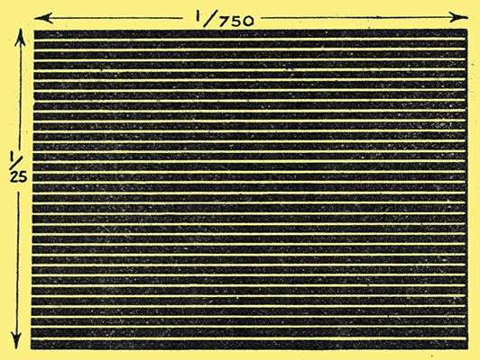
Fig. 1. - Two dimensional scanning for cathode-ray television.
Although the general principles of cathode-ray television have been previously described, it may be well just briefly to recapitulate them. The typical feature is the use of scanning voltages of the linear saw-tooth type for the framing and line scanning motions of the light source, which is, in this case, the fluorescent spot produced on the screen of the oscillograph. Generating circuits for the production of such voltages were described in previous articles. A simple impression of the result is given in Fig. 1, which shows the path of the spot in a 30-line scan, and at the rate of 25 frames per second. During 1/750 second the spot moves horizontally, with a sharp return, during which it is also moved down in a sort of ratchet movement, so that it traces its next path in a slightly lower position. At the end of 30/750 = 1/25 second it has travelled to the bottom, and is abruptly returned to its original position, so that it repeats the course shown every 1/25 second.
This is the condition in the absence of a picture and the eye. Watching the tube gives the impression of a streaky oblong of fluorescence. Actually it is less streaky than Fig. 1, since the scanning lines used with cathode-ray television are at least 120 per frame, this being the number employed in the Cossor system.
During each line movement (Fig. 1) the brightness of the light produced by the spot is caused to vary in accordance with the impulses from the transmitter scanning. In cathode-ray television practice this is usually done by some form of 'intensity control' electrode, which varies the instantaneous intensity of the electron beam, and, therefore, also the brightness of the fluorescent spot in accordance with the picture voltages. The ordinary type of cathode ray tube gives a very small range of intensity control without being accompanied by a defocusing effect on the spot, and special electrode systems have to be arranged for good intensity modulation.
The Cossor system, as already stated, therefore uses this intensity effect only as an auxiliary, and does its main picture formation by means of the velocity modulation system.
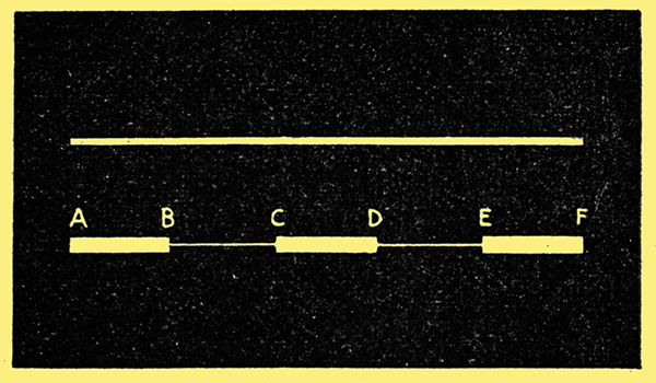
Fig. 2. - Principle of velocity modulation. The top line, is scanned at uniform speed. The bottom line is scanned with a slow movement from A to B, a quick movement B to C, and so on.
This method of modulation uses a scanning system exactly similar to that already described, but is based on the tact that the brightness of the light produced by the moving spot is proportional to the time taken by the spot to travel any particular length along the scanning line. For example, in Fig. 2 the top line represents the effect of a scanning line which takes a certain time to travel from A to F, doing so in a uniform manner, The lower line takes exactly the same total time to travel the distance A to F, but does so in an erratic manner, moving slowly from A to B, producing a bright response, very quickly from B to C, producing a very feeble response, then slowly from C to D. The impression of brightness conveyed to the eye thus varies with the speed, and it will be seen that dark patches on the reproduction correspond to places where the spot is moving rapidly, and light patches to places where it is moving slowly.
One of the advantages claimed for the Cossor system is the absence of the synchronising problem in the line scanning direction, and that it gives a simple solution of the synchronising problem in the picture traversing dimension, including the imposition of automatic framing. The lack of a need for synchronising of the line scan is due to the fact that a cathode-ray oscillograph is actually used as the scanning device, and the picture is formed on this tube itself. In the simplest case it is then only necessary to common together the plates of the transmitting and receiving tubes by means of a wire or radio link.
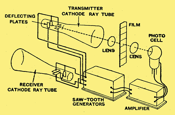
Fig. 3. - The essential layout for velocity modulation television.
This is schematically illustrated in Fig 3, but it will be seen that this, in practice, involves two transmission channels. This has been avoided by using one channel to connect the horizontal deflections of both tubes for line-synchronisation, while the framing synchronisation is effected by a signal impressed on the scanning.
In the Cossor system, using their own tube of standard dimensions, the size of picture on the transmitting tube is 6 cm × 8 cm, the tube working with an anode voltage of 500. In the velocity modulation system each scanning line must be produced by the same total deflecting voltage, that is to say, the length of each scanning line on the tube must be the same even although they need not all take the same time to sweep this distance (according to the amount of light and dark encountered.in the scan). It is thus possible to express the size of picture in terms of deflecting voltages, these being 380 for the horizontal line scan and 285 for the framing scan.
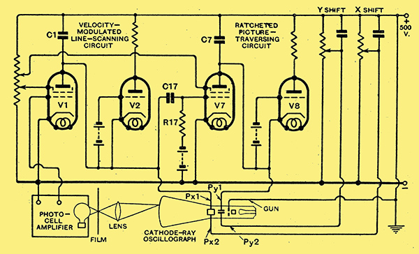
Fig. 4. - Skeleton circuits of Cossor transmitter, V1, C1 and V2 form the line-scanning saw-tooth generator, V7, C7 and V8 the framing saw-tooth generator.
The electrical outline of the Cossor system is shown in Fig. 4. The line scanning sawtooth voltage is generated by the screen-grid valve V1, capacitor C1, and thyratron (neon) V2, the circuit being a well-known one for deriving sawtooth voltages for time bases with cathode-ray tubes. The principle is that the valve V1 operates under constant-current conditions and allows the relatively slow building up of a charge on C1. This builds up until it reaches a voltage sufficient to trigger V2, which abruptly discharges the capacitor. The rate of building up the charge on C1 is governed by the voltage on V1, which is applied from the output of the photocell amplifier, and therefore on the amount of light passed in any scan line. The frame scanning is also derived from a similar sawtooth generator comprising the valve V7, capacitor C7 and thyratron V8. The building up of the voltage across C7 is controlled by the receipt of impulses from V2 via the capacitor C17. This capacitor receives an impulse on the abrupt discharge of C1 through V2. The valve V7 is operated on a saturated part of its anode volts/ anode current characteristic, so that each impulse from V2 causes the addition of an equal charge to C7 until it reaches a final charge sufficient to flash the thyratron V8, for the return of the framing impulse. In between each of the scanning lines the spot is depressed for the trace of the next line somewhat after the manner of a ratchet movement.
The line-scanning and framing voltages are thus applied respectively to the horizontal and vertical deflections of the oscillograph in the manner discussed in connection with Fig. 2 (except that, as already stated, 120 lines are contained in each frame). The rate of picture presentation is 25 per second, which is governed by an extra timing control circuit which is not shown in Fig. 4. This circuit is controlled from the 50 Hz mains, to which, being a sub-multiple, it is very easily locked at 25 per second.
For the transmission of a television picture the film is moved continuously (not in jumps as in ordinary cinema projection) between the transmitting oscillograph and the photo-cell lenses focusing the spot (in its instantaneous position) on to the cell, as shown schematically in Fig. 3.
The complete practical transmitting circuit contains a considerable number of additions to the simplified scheme shown in Fig. 4. The complete circuit is thus distinctly complicated, but the apparent complications are devised to place all the difficulties on the transmitter and make the operation of the receiver as simple as possible.
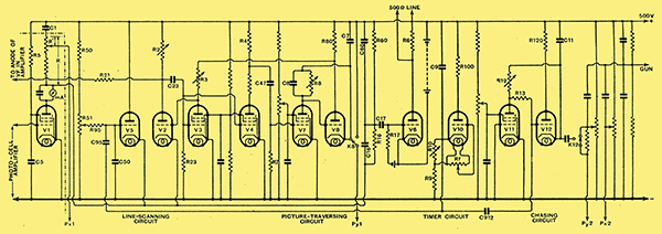
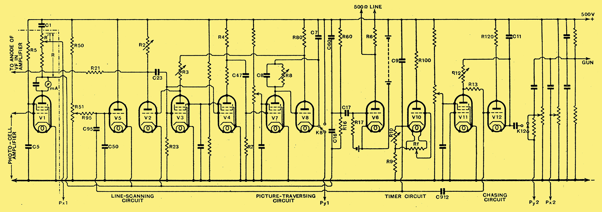
Fig. 5. - The complete scanning circuits of the transmitter system. The valve V1 is located in the photo-cell amplifier to minimise stray capacities.
The complete transmitter circuit is shown in Fig. 5, but it is impossible in this short account to discuss its operation in detail. The various sections are indicated below the diagram. The line-scanning system is similar to that already described, except that a pair of hard valves, V2 and V3, replace the thyratron V2 of Fig. 4, this giving a more stable circuit for operation at the relatively high-scanning frequency.
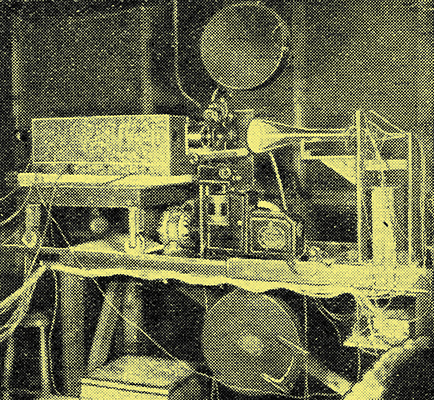
The transmitting equipment used for the experiments described in this article.
The picture-traversing circuit is also similar to that already described. The timer circuit is another saw-tooth generator (non-linear), operating, as stated, to impress the recurrence of 25 per second on the picture framing, the film being 'phased' by means of a take-up roller, so that the picture-change point coincides with the timer pulse. The 'chaser' circuit performs an auxiliary operation in scanning, which need not be considered in this short account.
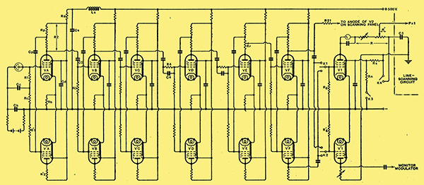
Fig. 6. - The circuits of the paraphase photo-cell amplifier.
The photo-cell amplifier is illustrated in full in Fig. 6, and contains an immense amount of circuit detail, the discussion of which would call for a lengthy article of its own. The essential features can, however, be indicated. These are:
- A voltage gain of the order of 5,000;
- effectively flat response characteristics from 25 to 240,000 Hz;
- a minimum of phase distortion;
- minimum phase delay;
- low valve and set noise;
- low level of microphonic noise;
- freedom from any form of instability;
- freedom from pick-up, e.g., of the scanning voltages;
- preferably mains-operated.
The Cossor system as so far developed has only been operated over a short wire channel. The output of Fig. 5 could, of course, be applied to modulate a radio transmitter, although in the present conditions it has been joined directly to the receiver. The receiver is intended to be operated by signals of low level such as could easily be obtained from a detector.

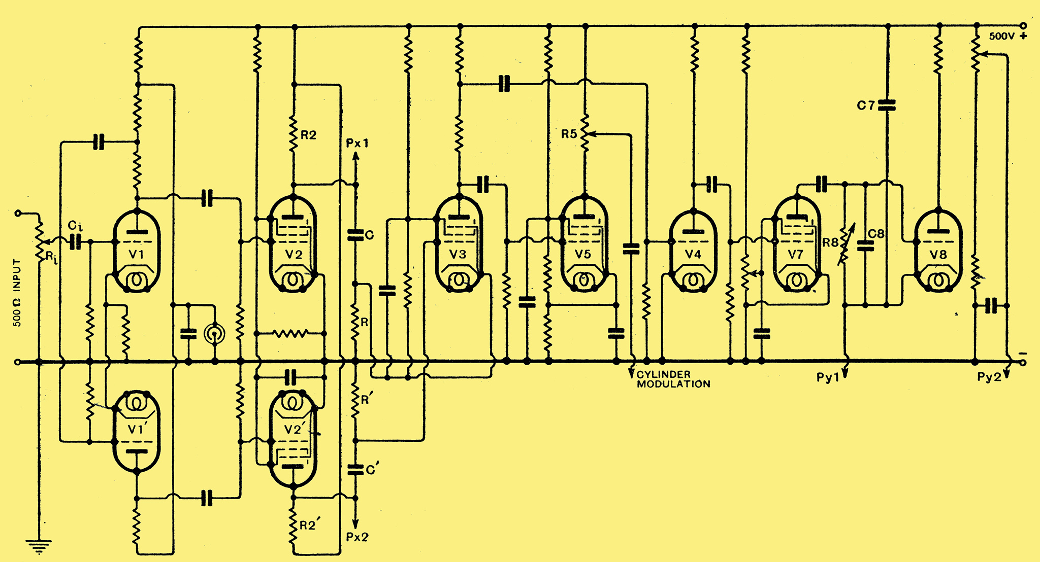
Fig. 7. - The television receiver circuit.
The circuit of the television receiver after such a detector is shown in Fig. 7. The size of the picture is approximately that of 440 Volts × 330 Volts, the former being that of the line-scan and the latter that of the ratcheted frame timebase. The main incoming signal is the line-scanning, which receives two stages of push-pull or paraphase amplification before being passed on to the horizontal deflection plates (PX1, PX2, of Fig. 7). A part of the same output is also applied to a valve V3, and through it to V4, which controls a picture-framing, sawtooth generator V7, C8, and V8 (thyratron) exactly similar to the corresponding circuits at the transmitter, and therefore operating in synchronism with its impulses.
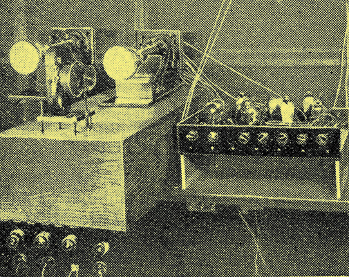
The apparatus associated with the receiver.
These constitute the essential parts of the receiver for the pure velocity modulated reproduction of the picture. The valve V5 controls the 'intensification' process, which is obtained by combining an auxiliary contribution of intensity modulation with the chief action of velocity modulation. It has already been stated that the ordinary type of oscillograph is not suitable for use on intensity modulation as its chief work, but it gives a reasonable degree of control of the intensity of the beam which can profitably be utilised. While the main output of the television transmitter (Fig. 5) is the line scanning impulses of velocity modulation, it can be shown, both by theoretical reasoning and by analysis, that it also contains a component which is similar in nature, although possibly not so great in magnitude, as would exist in a transmitter using intensity modulation. It can also be shown that the circuits CR and C1 R1 in the anodes of the valves V2 and V21 act as differentiating circuits, using the word in both its mathematical and physical meanings. This permits that component which is equivalent to intensity modulation to be handed on to V5, from the anode circuit of which it controls the potential of the oscillograph cylinder in order to obtain the intensifying effect in reception.
The operating controls of the receiver are extremely simple, due to the inherent nature of the system and the arrangement of the transmitter. The input potentiometer Ri is adjusted to give the required breadth of picture, and the screen voltage of V7 is set to give the required depth. There is no synchronising adjustment, even for framing, because R8 and C8 are fixed at the correct values. The remaining controls are the intensification volume control R5, and, of course, the focusing of the cathode-ray tube by the usual methods. The above adjustments can only be made while the signal is actually being transmitted and received.
Future possibilities which are envisaged in the improvement of the system lie in the direction of tube design and manufacture. For example, in the receiver tube a 9 inch screen appears a satisfactory compromise, and the design of a tube of this size, also of hard tubes, is in progress. So far as the transmitter is concerned there appears no doubt that the scanning lines could be raised to 150 or 200 at which the theoretical detail approaches that of the home cinema.
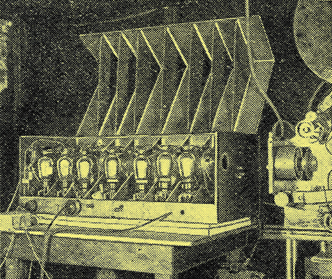
The cathode ray amplifier.
|