|

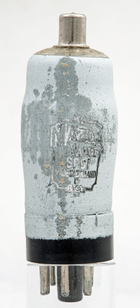 
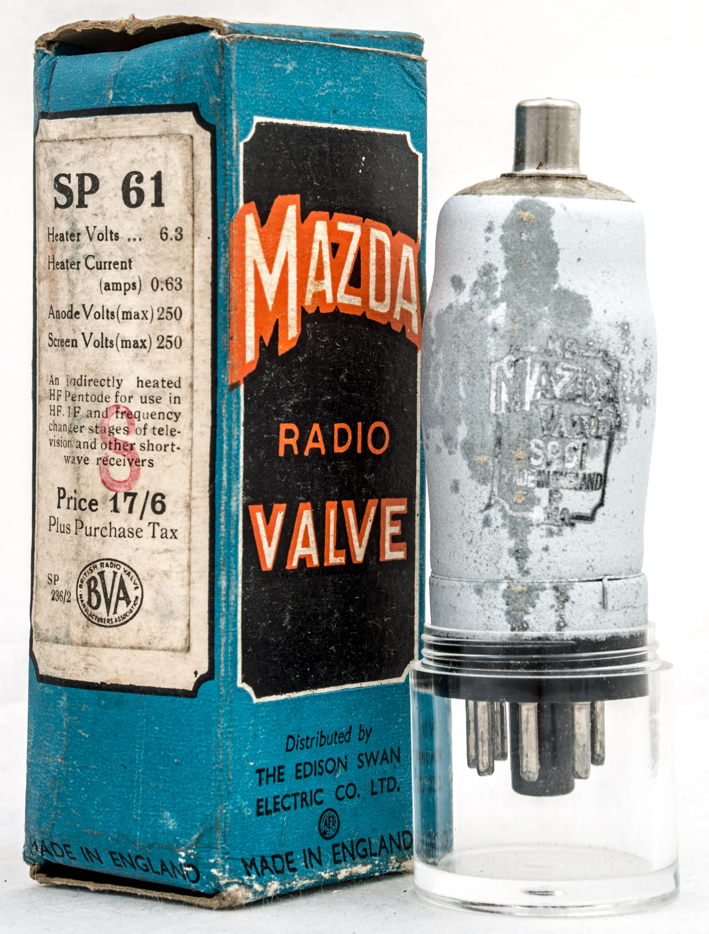
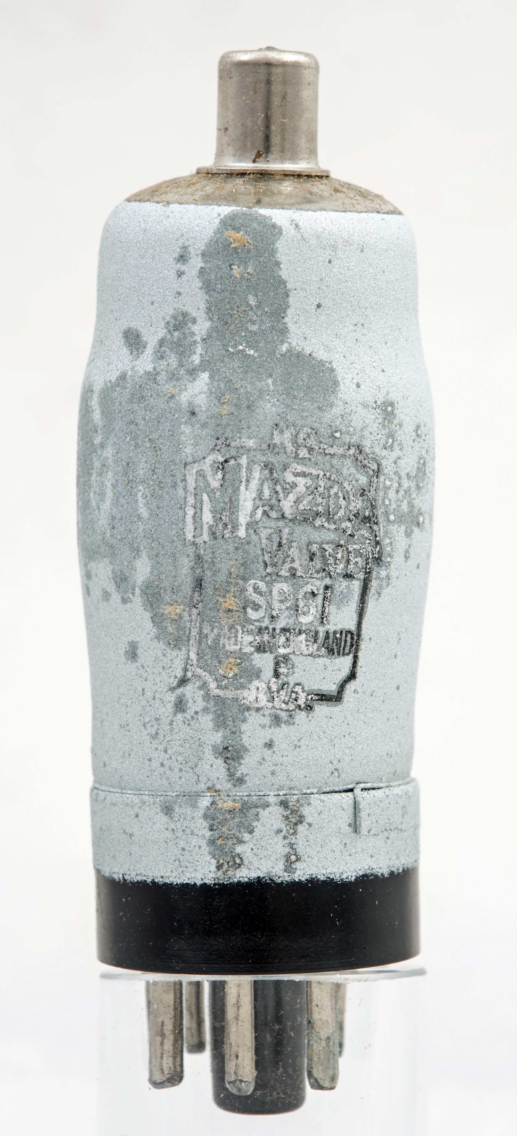
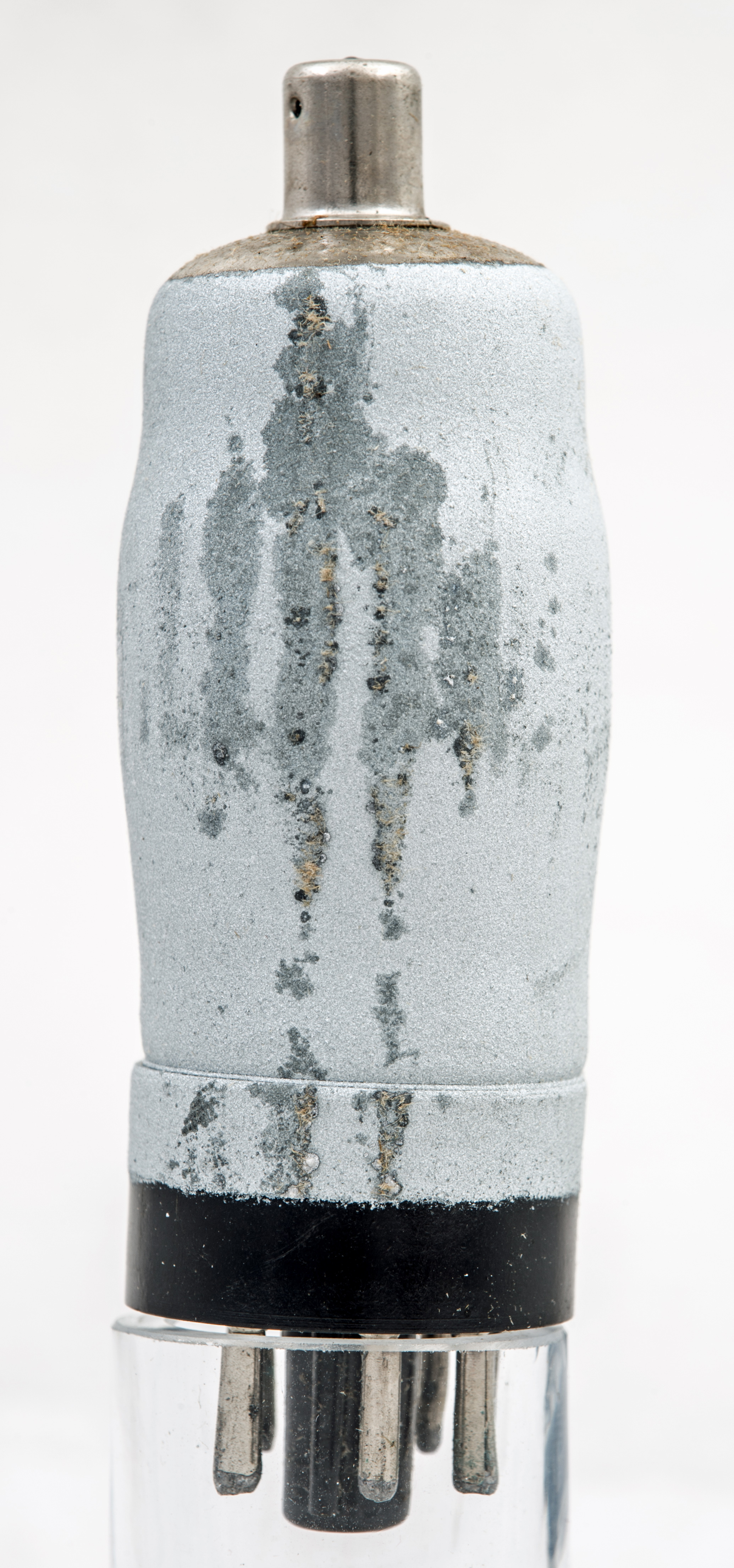
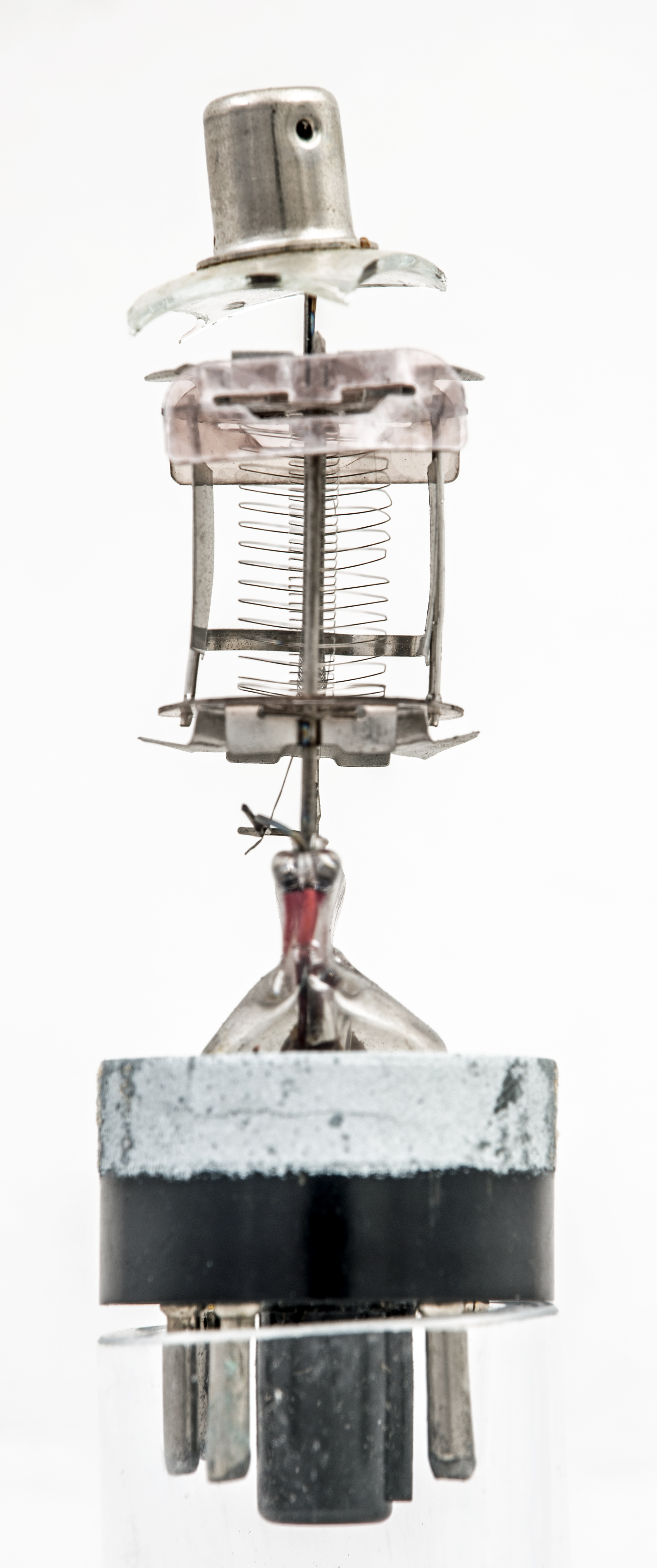
The Mazda SP61 before breaking the envelope.
The metallising lead from the base is in the foreground of the left image. The wire passes in a complete loop around the top of the base cap.
The valve measures 32.47 mm in diameter and id 81 mm tall excluding the base pins. The MO base is 29.36 mm in diameter and 15.38 mm high. The central spigot is 8.74 mm in diameter ignoring the key and 13.33 mm long. The pins are 2.3 mm in diameter and 10.83 mm long. The top cap is 9.13 mm in diameter and 10.65 mm tall.
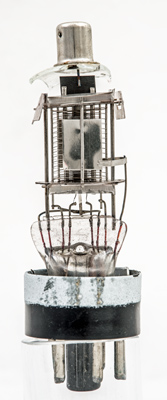
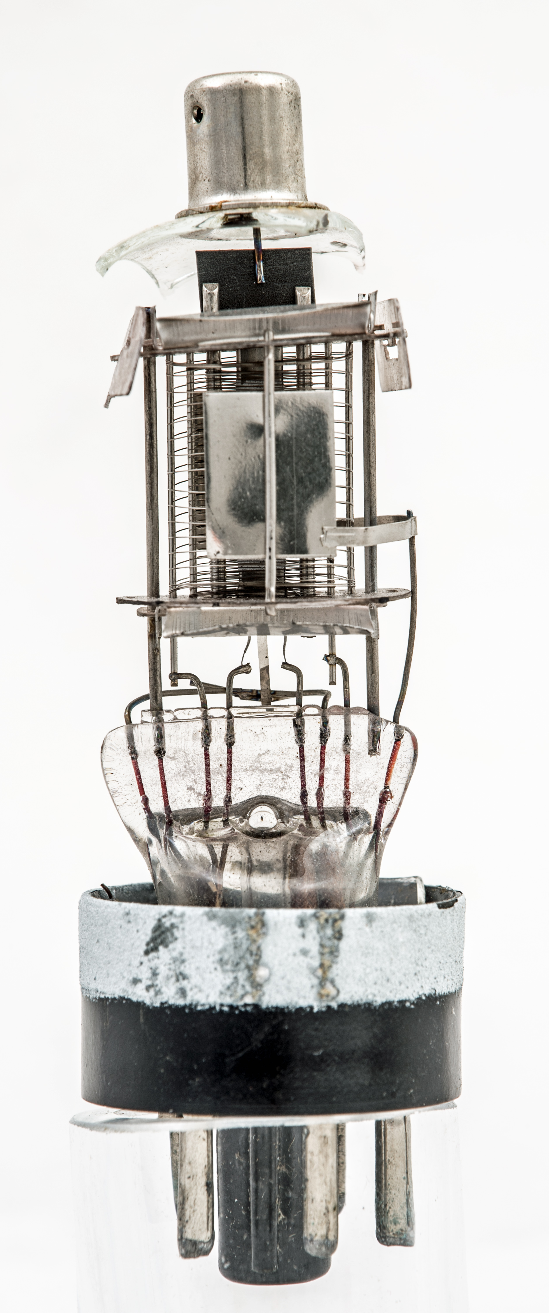
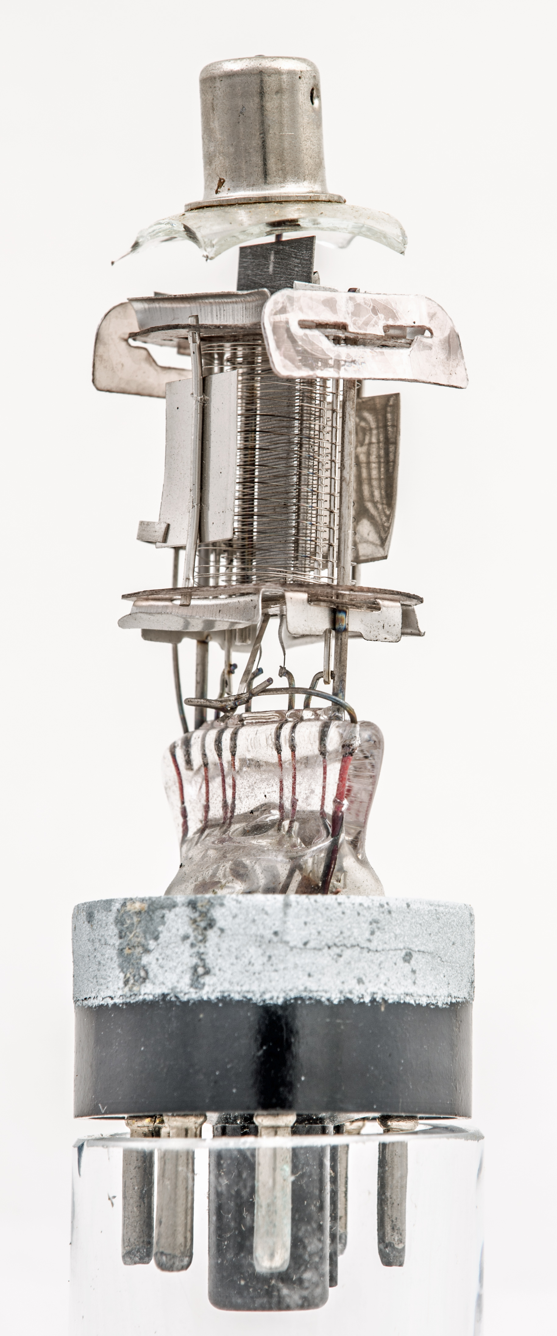
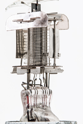
First view of the valve insides.
The valve was placed in a double layer of polythene bags to contain any splinters and getter dust. The glass envelope was tough to break. In the end a large squeeze cramp was placed round the centre and closed until the glass shattered. This way the inner structure was not touched.
Constructional is conventional with a pinch stem and large fan pinch. The leads are much longer than those of the EF50 and there is little screening under the lower mica. The glass was measured at 0.92 mm thick.
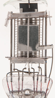
The anode consists of two small flat plates 10 × 12.5 mm joined by a tape strap. The anode lead is kept away from the other wires and enters the pinch on the extreme right.

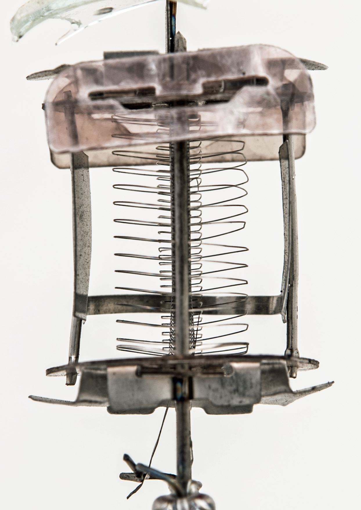
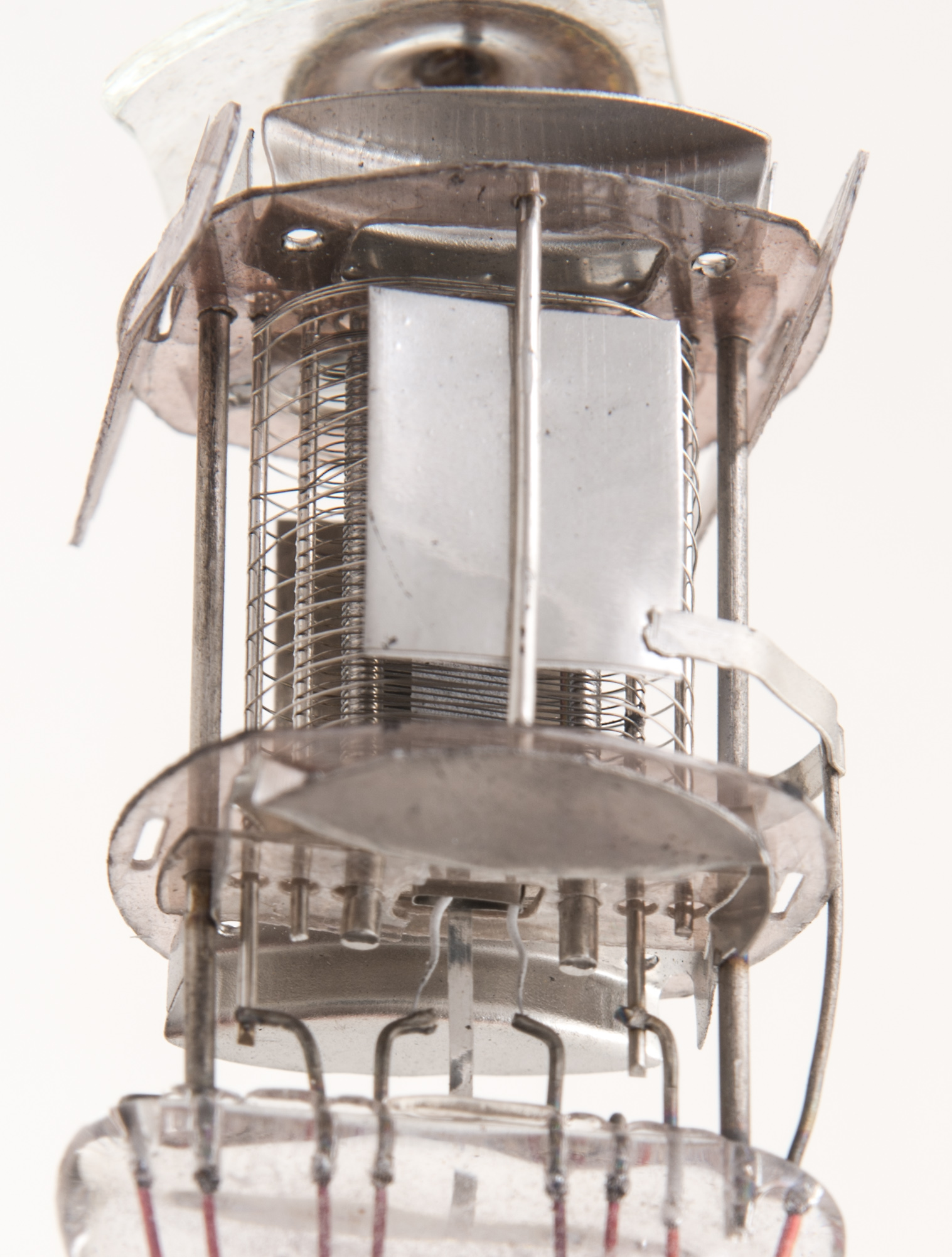
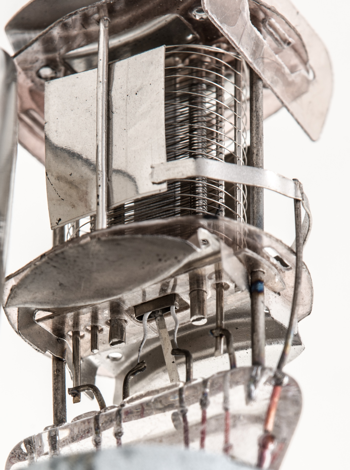
Looking along the grid axis.
The mica rectangles at the top hold the electrodes firmly in the envelope. The electrodes themselves fit into the 19 mm space between the mica discs. The outer suppressor grid has a reasonably close pitch and is brought out to a separate pin. This enables it to be used for dual control.

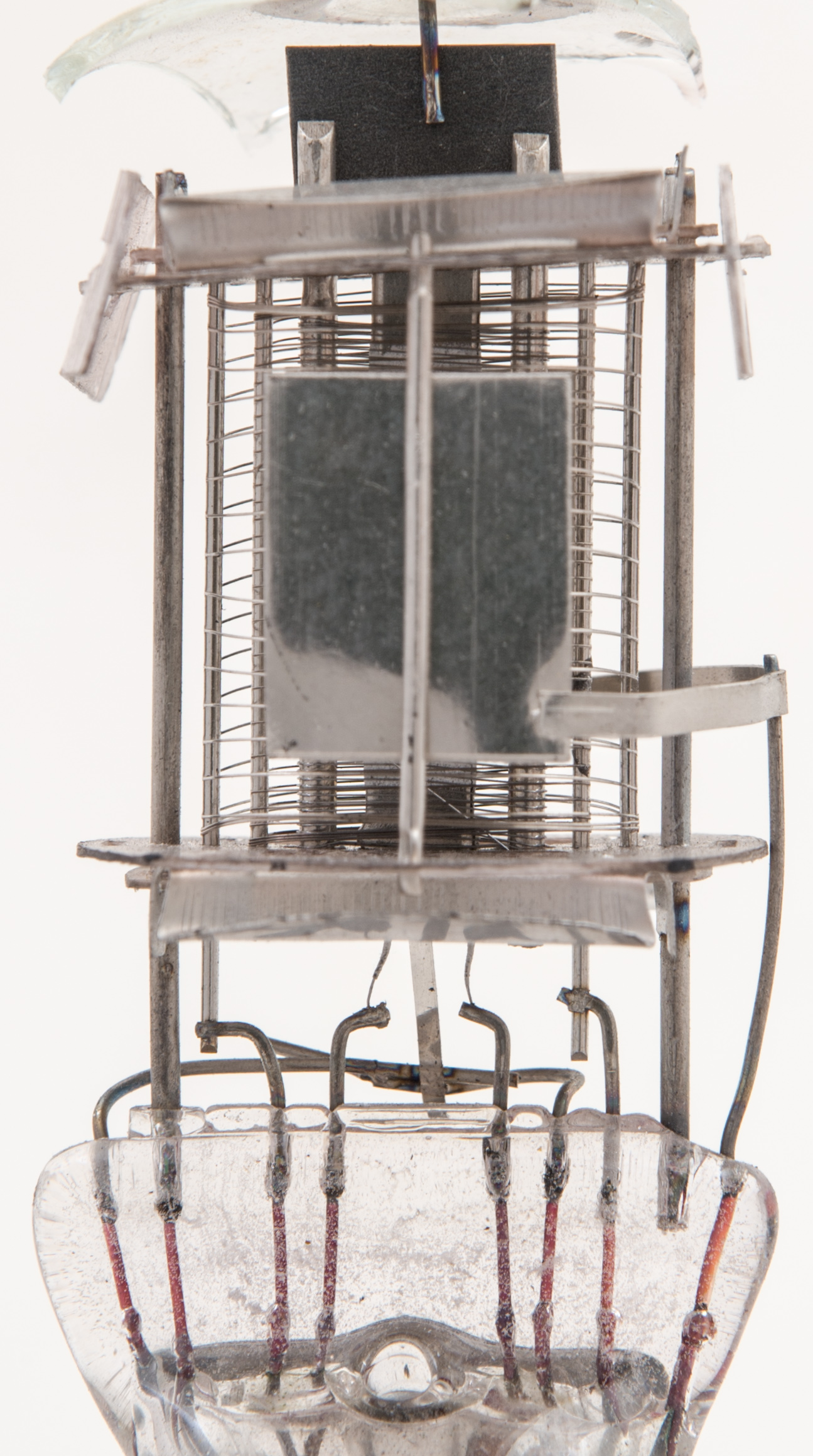
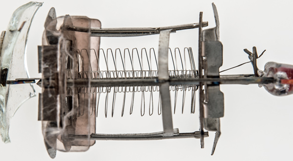
The flat rectangular cathode.
The rectangular cathode tube is 3.5 mm wide and the grid wires pass flat across the coated surface. The cathode connects to the pinch via a tape rather than a wire to lower lead inductance. Additionally the cathode lead passing through the pinch is thicker than the rest of the wires.
The control grid is wound tight round the support rods whereas the other grids are shaped to be wider than the supports. The control grid supports are much thicker than the other grid support rods at 1.5 mm in diameter. It looks to be a halfway house towards the frame grid. The heat sink fin at the top of the control grid is spot welded to the supports and thus adds rigidity as well as being able to cool the control grid.
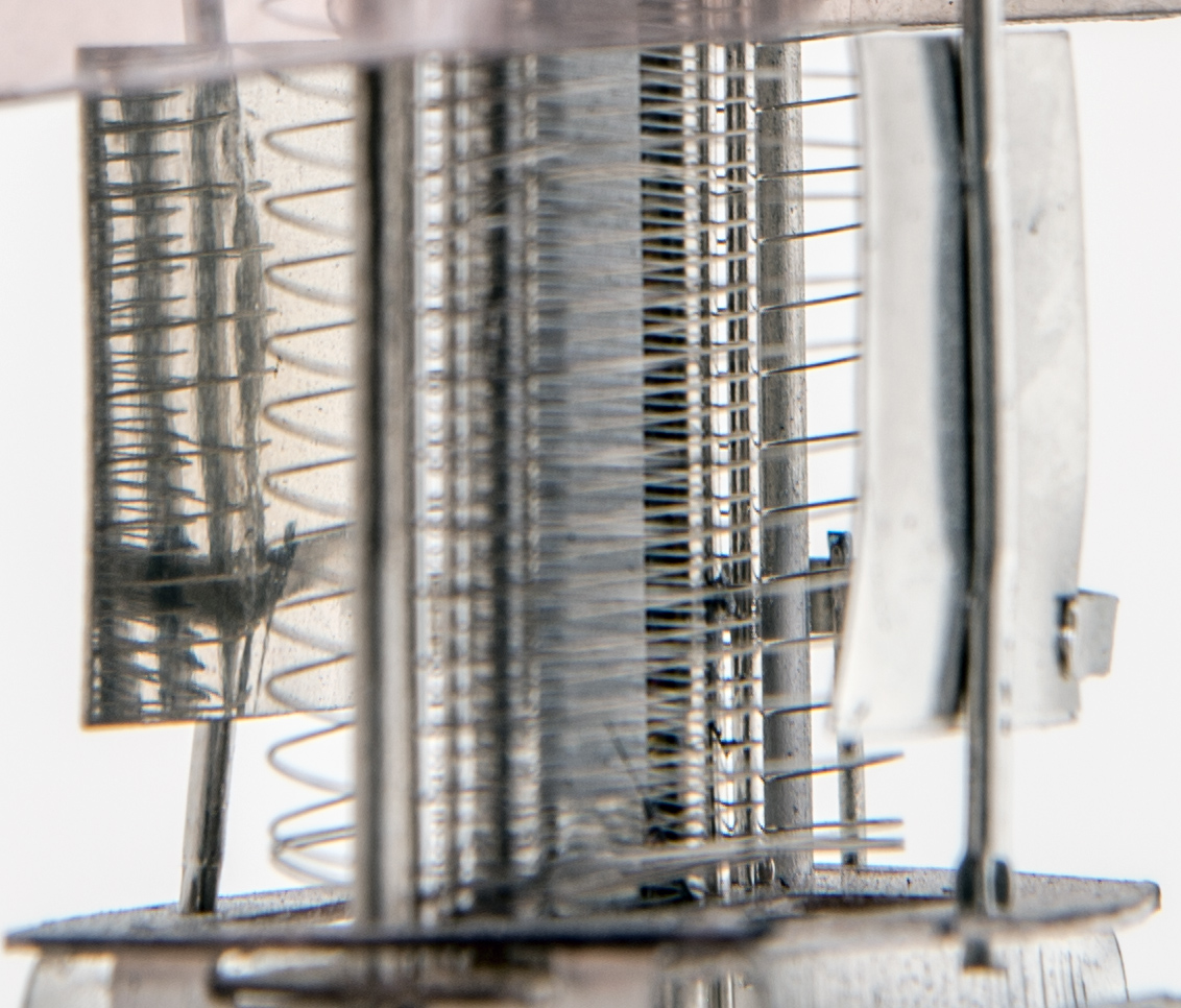
A closer view of the grids.
Measuring on the screen from the full size image the grid pitches look to be:- g3 = 1.5 mm. g2 = 0.67 mm and g1 0.28 mm.
The space between the anode plates is 14.5 mm. The suppressor grid supports are set 12.85 mm apart and the screen grid supports are 9.3 mm apart.
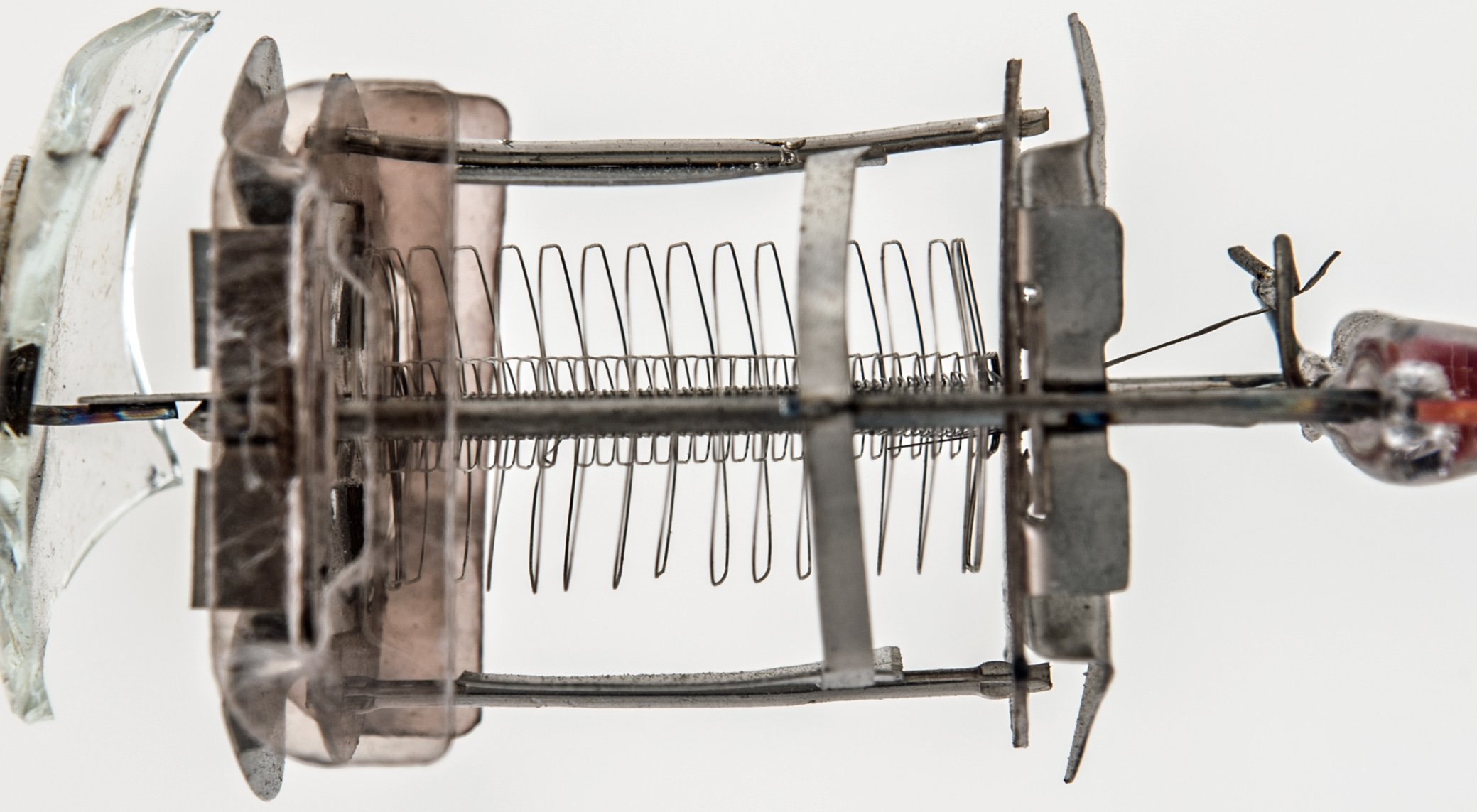
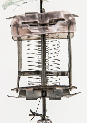
Below are some other close views of the SP61 structure. The heater is a single inverted V insulated single strand wire. The electrodes are spot welded to wires fixed into the pinch. However, the main vertical supports (1.3[m]mm in diameter) fit directly into the pinch and are set 17.93 mm apart as measured to the outside edges. Thus the valve would be assembled onto the fixed supports.
 

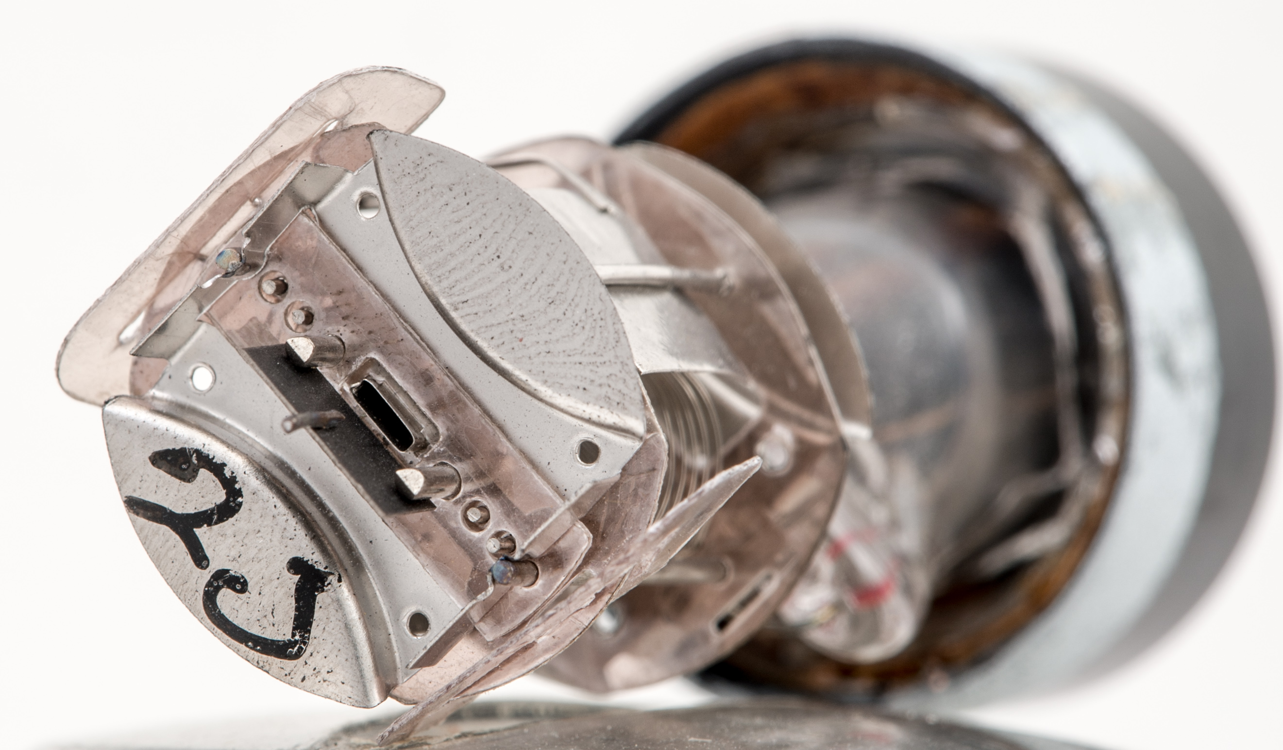
The top of the electrodes after removal of the top cap.
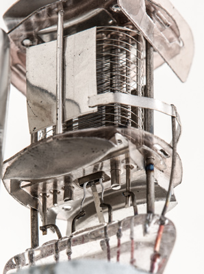
Another view of the lower mica components.
|