|
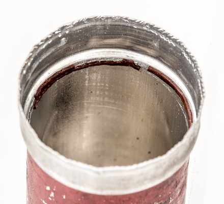
The Air Ministry VR91 with the folded lip of the outer can lifted.
The aluminium screening can is 0.4 mm thick.
The spigot that covers the evacuation tube and pins.
The base spigot and base cover looks to be made of zinc. The cover is 35 mm in diameter and the metal is 1 mm thick. The spigot is 15 mm long and 6.5 mm in diameter. The circular depression near the tip is to allow the valve holder central spring to hold the valve in place. The Loctal valves have a more pronounced locking mechanism. In practice the EF50 used in aircraft would spring from the holder. The solution was the two part valve-holder that had a screw down locking ring.

The all glass EF50 inside the aluminium screening can.
With the can lip opened out the valve was expected to slide out - it did not.
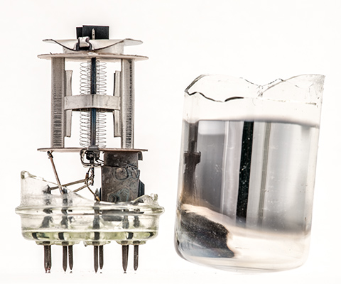
The vacuum seal broken.
The vacuum was broken by holding the valve over a small pot and crushing the tube with a pair of smooth jawed pliers.
The envelope emerging from the can.
The glass envelope would not easily come out of the can. The open end of the aluminium can was opened slightly with the smooth jawed pliers to give extra room for the glass to be withdrawn. The image shows the clear glass of the main envelope and the slightly greenish tint to the hard class base.
The cement ring inside the outer can.
The reason the valve would not easily come out of the can was a ring of cement between the can and the glass. A previous EF50 opened by the author did not have the cement ring.
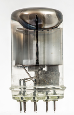
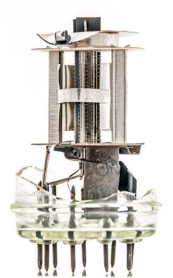
The all glass EF50.
The inside structure revealed.
A glass cutter was tested on a flat piece of picture glass and one stroke and a gentle tap was all that was needed to cut the glass. The cutter was run round the envelope and hardly a mark was made. After several passes round the envelope and ever heaver taps finally opened the envelope.
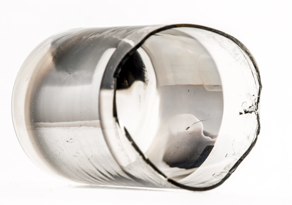
The main envelope.
The getter at the top of the envelope was initially black but after a few minutes exposed to the air the getter turned milky. The bright wide band around the middle looks to be present to stop the electrons that reach the glass from knocking gas out.
The valve envelope is 31.4 mm in diameter and 56 mm tall. The glass is 0.95 mm thick at the opened end.
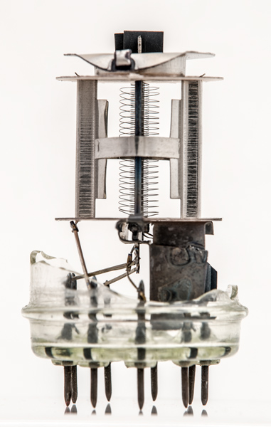
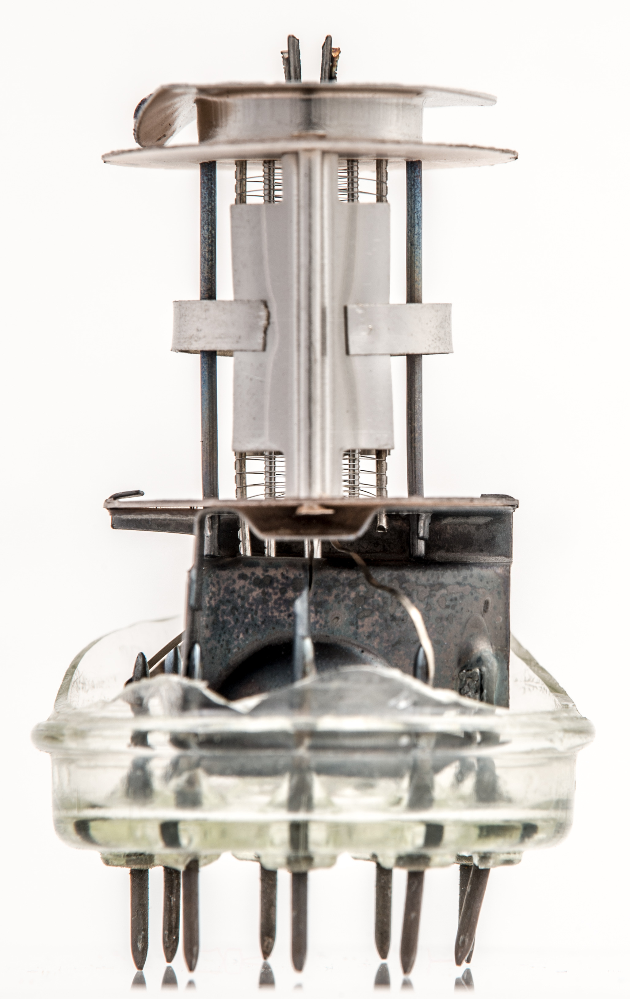
Looking along the grid axis.
The heater is made from a length of insulated coil. The anode is made from a pair of pressings joined by a strap. Thus the centre electrons have further to travel than those that meet the wider section. There are three elliptical grids around a round cathode. The control grid has a pair of small heat radiating fins attached at the top.
The suppressor pitch is 0.84 mm. The screen grid pitch is 0.323 mm.
The strap on the anode is spot welded in place.
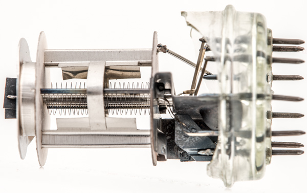
The space between the mica discs is 20.91 mm and the discs are 25.4 mm in diameter. The main part of the anode is 9.6 mm from side to side and 14.6 mm tall. The strap is 3.0 mm from top to bottom. The outside edges of the suppressor grid supports are 9.38 mm apart. The screen grid supports are 5.5 mm apart. The fins at the top of the control grid are 6.0 mm wide and 4.0 mm top to bottom. The outer edges of the anode plates are 10 mm apart but at the centre, where the deep grooves are, the outside measurement is 19.14 mm.
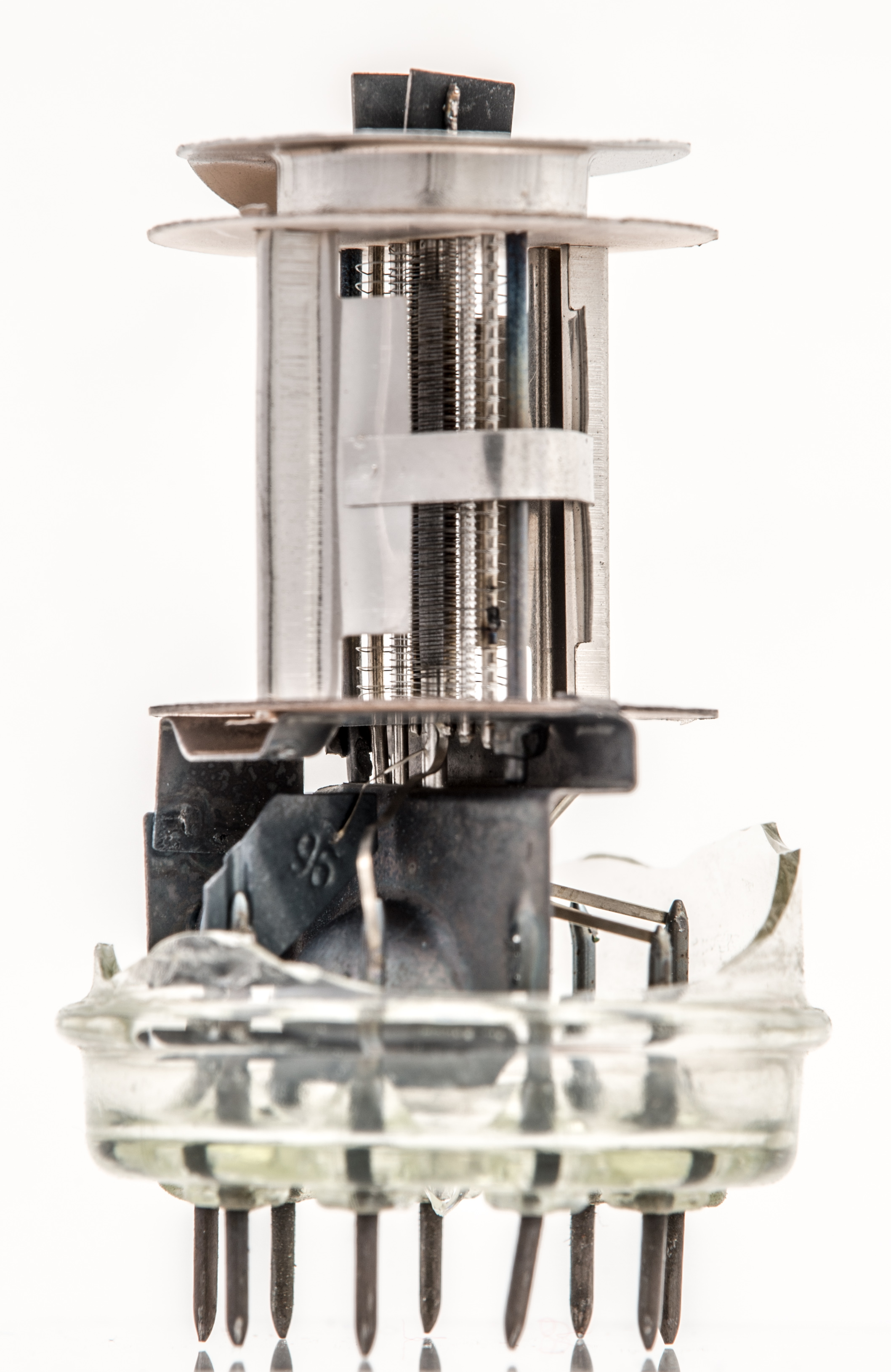
The large L shaped central screen below the lower mica shields the cathode and control grid from the rest of the electrodes. The anode connection is made at the outer edge. The cathode pin connects to the sail like fin seen on the right thus minimising the lead inductance.
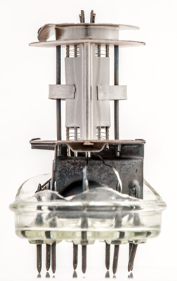
The anode has straps fitted on both sides. Below the lower mica this image is looking along the cathode connection with the control grid wire on the right.
This image is looking directly at the broad face of the main screen that is 19.44 mm wide. Note the bell shape in the centre.
The outer vertical rods are 13.53 mm apart and connect the lower screen to the top screen.

The lower screens are complex.
The main screen is welded to the trough screen under the lower mica.

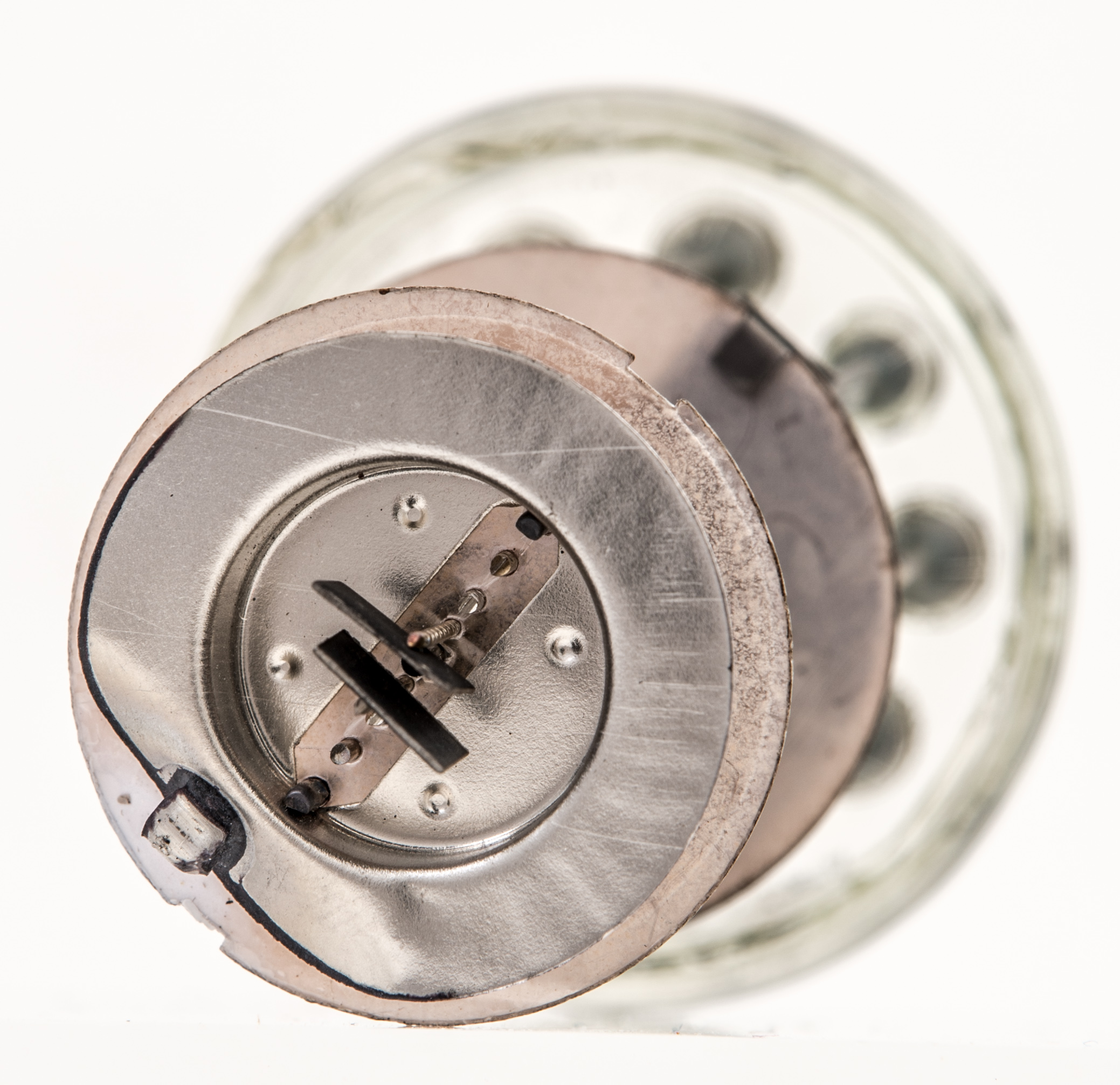
Looking down on the top of the electrodes. At the lower left is the getter holder.
The getter holder originally held a cylindrical pellet. The openings are at the side and the getter material when fired would escape along the depressed section of the top screen.
The inside of the base pins is brought to a point. The connections to the electrodes are made with a rectangular tape.
If the anode was a simple curved plate the centres would be 13 mm apart and this spacing would allow the central electrodes to fit into a B9A envelope.
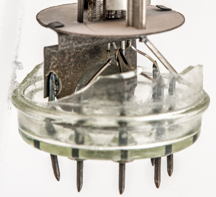
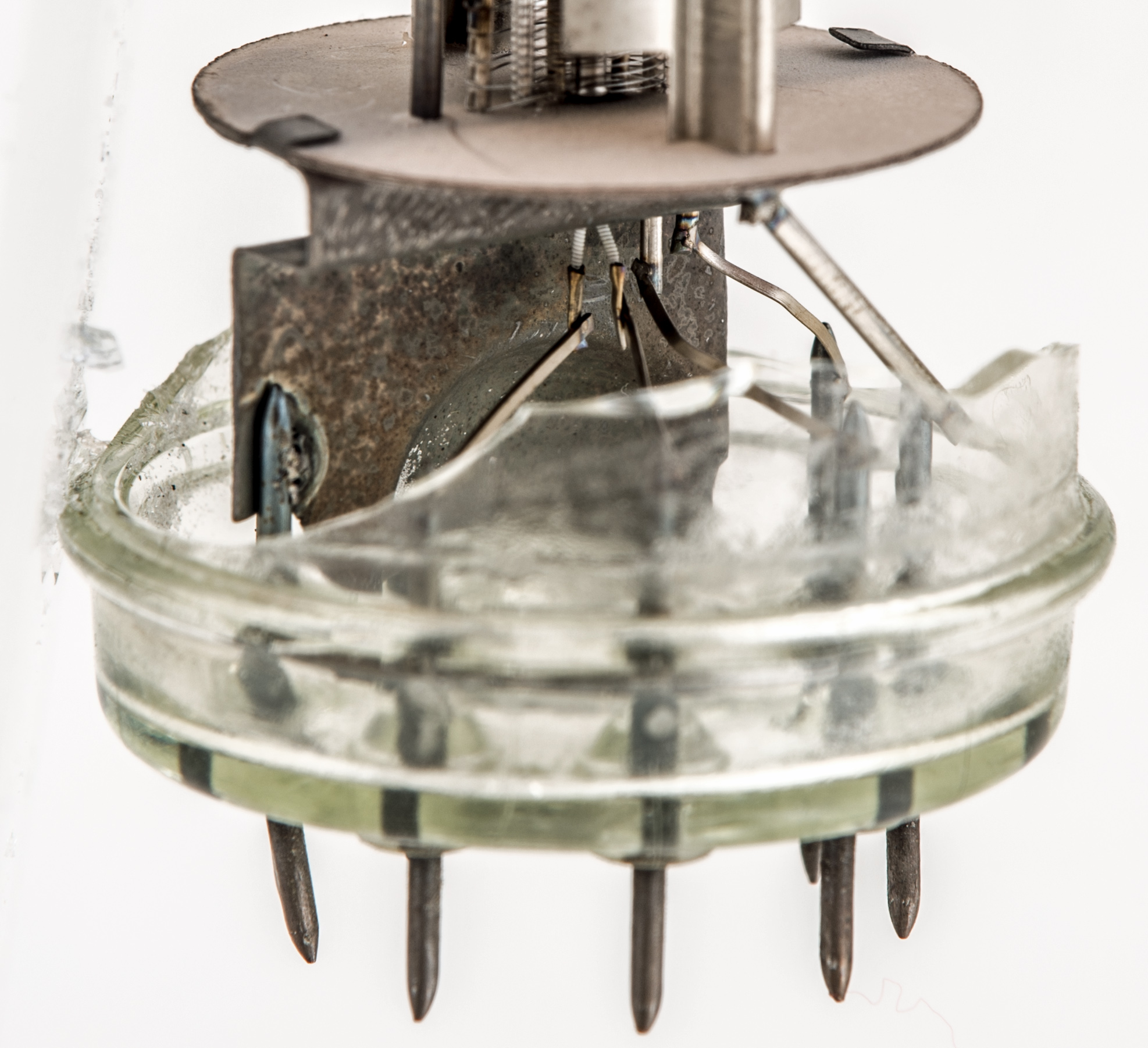
A closer look at the base pins and lower components including the heater wires.
The connection from left to right are heater, heater, screen grid, suppressor grid and finally the anode. The ends of the heater wire are set into small bore tubes that have been crimped to hold the wire. This is typical of connections to tungsten wire that has a melting point too high for spot welding.
|