|
The author was given a modulator from a Plessey PTR175 aircraft transceiver and asked if the 2E26 could be used as an audio amplifier.
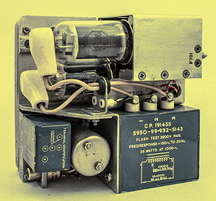
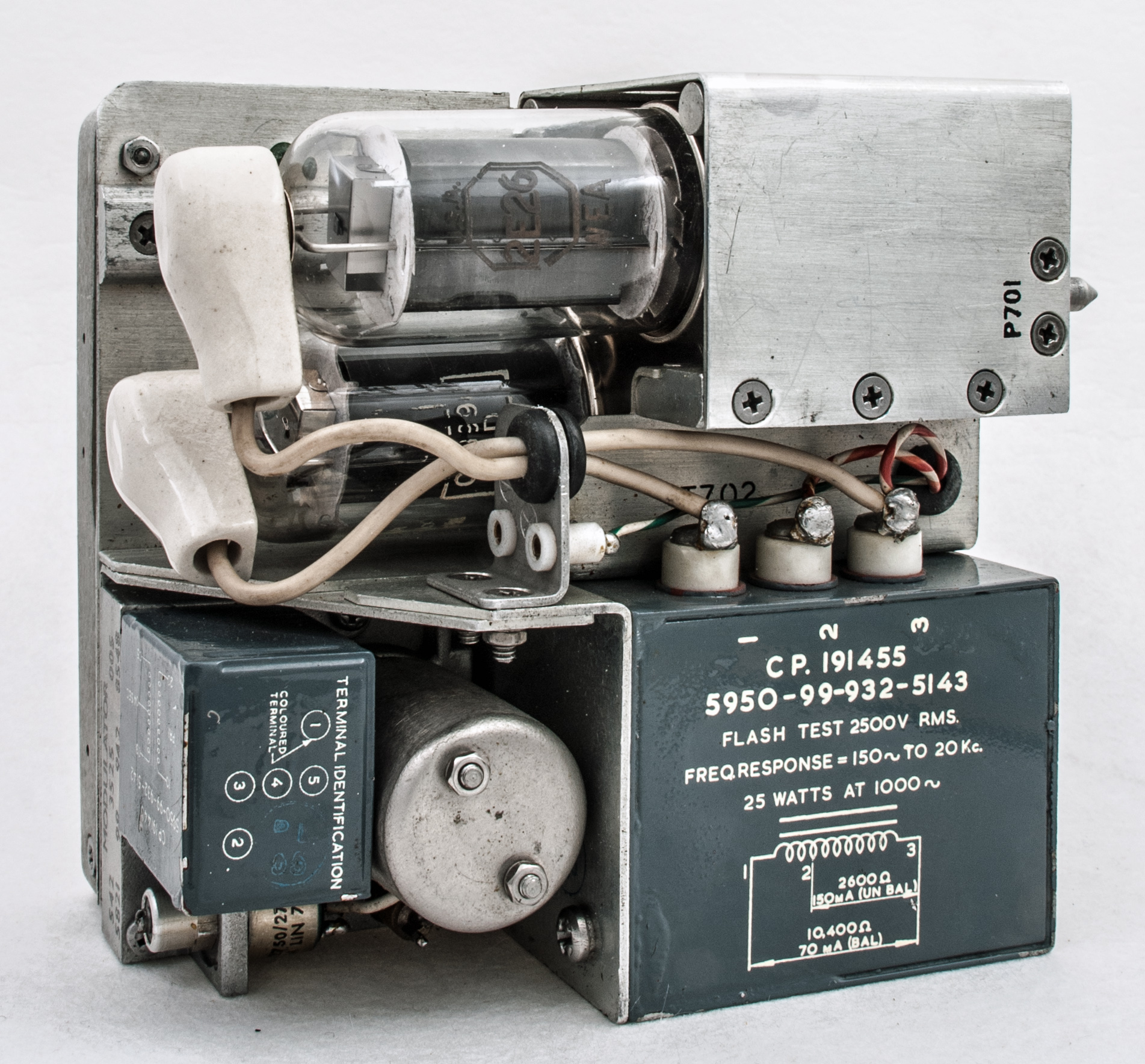
The original modulator. The Power valves are 2E26 and CV3990.
The author had been building and testing amplifiers for the previous weeks and so it seemed natural to work on the 2E26 design. A youtube video demonstrated the use of the 2E26 as a guitar amplifier and employed a 5 kΩ output transformer. Left over from the experiments with simplex stereo was a Chinese output transformer of the correct characteristics.
The 6AT6/EBC90 double diode triode had been successfully used in the Neophyte Amplifier of 1969 as input voltage amplifier and the author used the design for the phase inverter in the simplex stereo experiments. Having purchased a number of these small valves, it was natural to use another. The 6AT6 can be regarded as close to half an ECC83 but much cheaper. The unused diodes were strapped to ground.
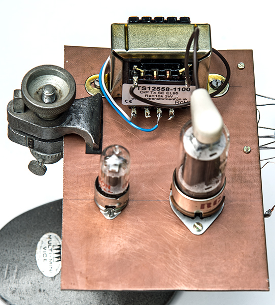
Top view of prototype.
The 2E26 data-sheet gives 200 Volts as the screen grid maximum and suggests that 160 Volts is appropriate. These characteristics remove the possibility of using the ultra-linear mode. The 6AT6 voltage amplifier works well at 160 Volts and thus a 160 Volt rail seemed a good idea - derived from a separate supply or a potential divider, or a Zener diode. Given that it was planned to use a regulated HT supply, the potential divider was the easy option - no 160 V Zenners in the 'Junk Box'.
The 2E26 as a Class A audio amplifier runs at 36 mA with a cathode bias of -14 Volts. A 400 Ω resistor (470 Ω power resistor shunted by 2.7 kΩ) bypassed by an electrolytic capacitor was selected. A 1,000 μF 25 Volt capacitor was to hand and so used.
The top caps of the 2E26 are of a greater diameter than the receiving types and having the ceramic insulated top cap connectors was be a distinct advantage.
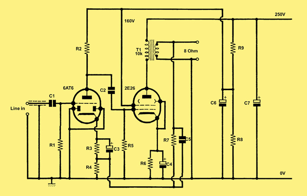
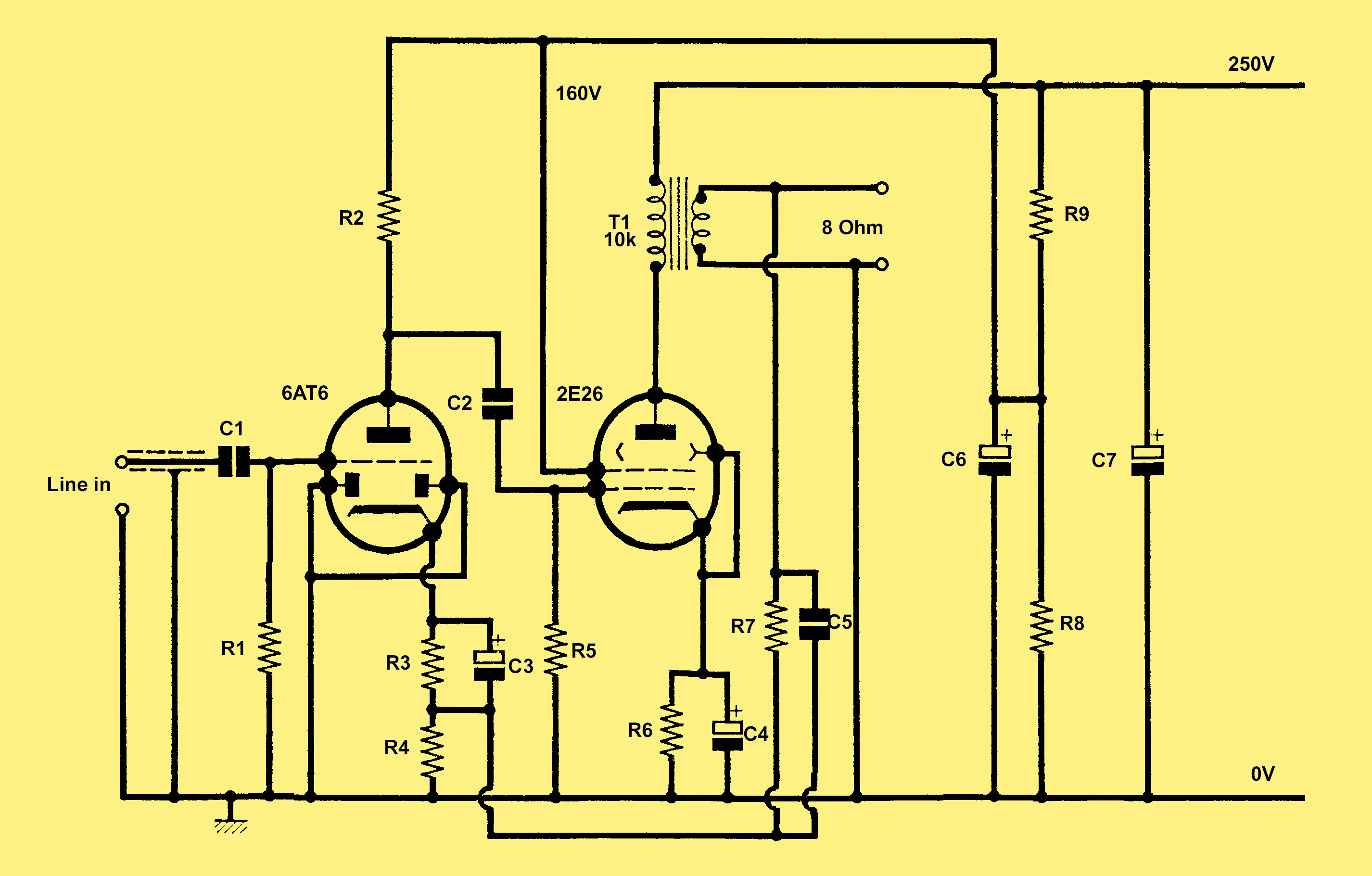
Circuit diagram. R8 should be replaced by a 160 Volt Zenner diode. A 1 kΩ grid stopper is mounted close to the 2E26 control grid.
A quantity of double sided copper clad fibre-glass board had been in 'stock' for a couple of decades and an off-cut was in the workshop. This was easy to work and provides a suitable mechanical platform. The copper was not connected or used as an earth-plane. The black output transformer See Simplex Stereo Re-visited. was mounted plus valve-holders. The Octal base required a 25 mm diameter hole and the B7G holder a 15 mm hole.
The circuit was wired-up and two power supplies hooked-up. The connections were poor and the screen grid started to pass excessive current. At this point the 160 Volt potential divider was made using power resistors that were to hand. With power from a single supply the amplifier drew the expected currents and could be tested. An eight Ohm dummy load was used. The oscilloscope trace showed some distortion and this was investigated. With the 5 kΩ anode load and the inexpensive transformer the second harmonic was only 12 dB down on the fundamental - poor. Connecting the oscilloscope to both the dummy load and the valve anode was revealing. The anode waveform had the second harmonic at -30 dB and the output into the dummy load still had the second harmonic of the 1 kHz sine wave at -12 dB. Time to replace the transformer. Having a pair of VVT Transformers [★] no longer trading EL95 SE 3 Watt devices available made a simple choice. The transformer is rated for 24 mA anode current and the 2E26 was running at 36 mA so it was possible that the core would saturate. In the event the results were good.
The dummy load was replaced by a Mission bookshelf speaker and mono recordings played to get an idea of the quality. The reproduction was good with no issues over a couple of hours. The input had to be kept low as the amplifier was sensitive.
Time to measure the performance. The amplitude across the dummy load was increased until the waveform started to show obvious distortion. Using the FFT facility on the Tektronix 2012 'scope the THD was measured and the signal level adjusted to give a total harmonic distortion of 10%. The output was 3.65 Volts - under two Watts.
Next the negative feedback resistor of 2.7 kΩ was connected. An oscillation at 39 kHz was soon found. Layout changes did not cure the problem, and adding more resistance reduces the feedback effect too much. Frequency selective feedback was the next step. A 1 nF ceramic capacitor was tack soldered into circuit and immediately the supersonic oscillation ceased.
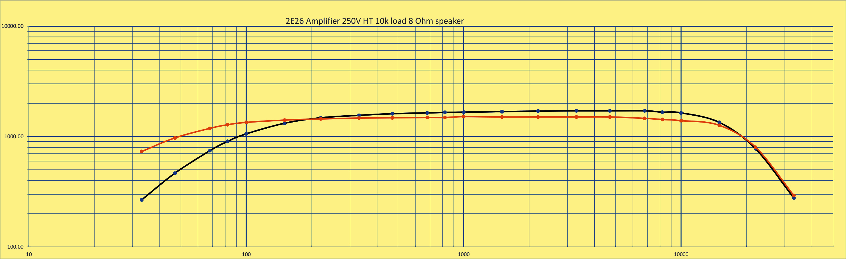
The amplifier with the feedback in place required four times the input amplitude to achieve maximum output - about the right level for line-out signals. The second harmonic of the 1 kHz input was now at -40 dB below the fundamental. Third harmonic at -32 dB and fourth harmonic at - 43 db. Giving a THD of 2.8% - very good. The power output at a range of frequencies was then recorded and plotted as shown below.
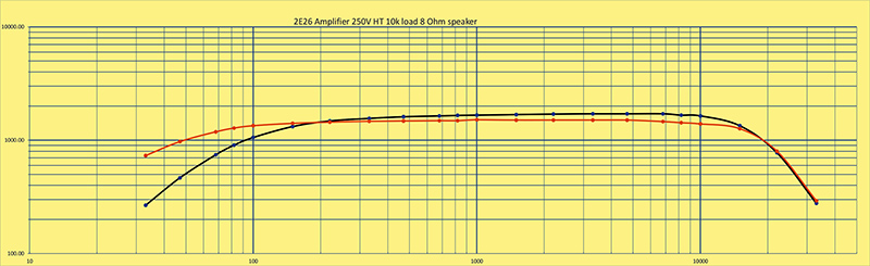
Performance curves. Black - no feedback, Orange - with feedback.
Reverting to the Mission speaker was a revelation. The sound was clear, full and most satisfying. The family standard listeners were recruited for a sound test and both agreed that the sound was a great improvement on the previous test. The increase in the bass response and a lack of colouration was observed.
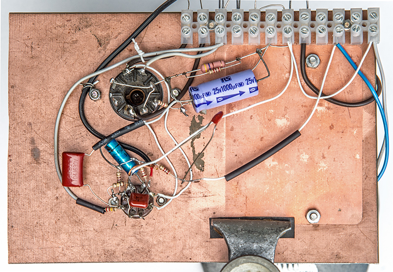
Underside of prototype.
The 2E26 can be used to make a decent single ended audio amplifier. The output with feedback is a little over 1.5 Watts but in practice the volume obtained is more than adequate to fill a room 4 x 7 Metres.
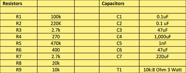
List of components.
|