|
Completing the Design for a 50-Watt Amplifier
This pre-amplifier for the 88-50 50 Watt mains amplifier is intended to offer full playback facilities from any known programme source and yet utilize circuits which are basically simple and economic. It will operate directly from a gramophone pickup, a high-impedance magnetic tape replay head, a high-impedance microphone or a radio tuner. A selector switch which enables any of these sources to be chosen also automatically alters the input sensitivity and frequency response compensation to that required for each type of input. This enables the different inputs to be selected and played without immediate alterations to the remaining knobs which are intended to give convenient control of balance and frequency range to suit listening conditions and programme quality. A rumble filter is incorporated which attenuates unwanted motor rumble below 30 Hz [2] In the 1950's the unit was cycles per second or c/s and removes the risk of overloading the power amplifier and loudspeakers due to this cause.
The pre-amplifier is designed to give an output of 0.5 Volt RMS for maximum signal level, and this corresponds to the input required by the 88-50 power amplifier to give maximum power output. HT and LT supplies are derived from the power amplifier, and connection is via octal plugs and sockets with a multi-core cable.
The design utilizes negative feedback to keep harmonic distortion low. All the controls use simple resistance-capacitance circuits incorporated either between stages or in the negative feedback loops, and the wiring is not unduly complicated. Apart from the equalizing of initially differing programme sources by means of the selector switch, the use of continuously variable controls for Bass, Presence, and Treble Slope helps circuit simplification and also removes the bullying effect that switches have on the listener when he is trying to adjust a programme to suit a particular place or occasion.
Input Selector Circuit
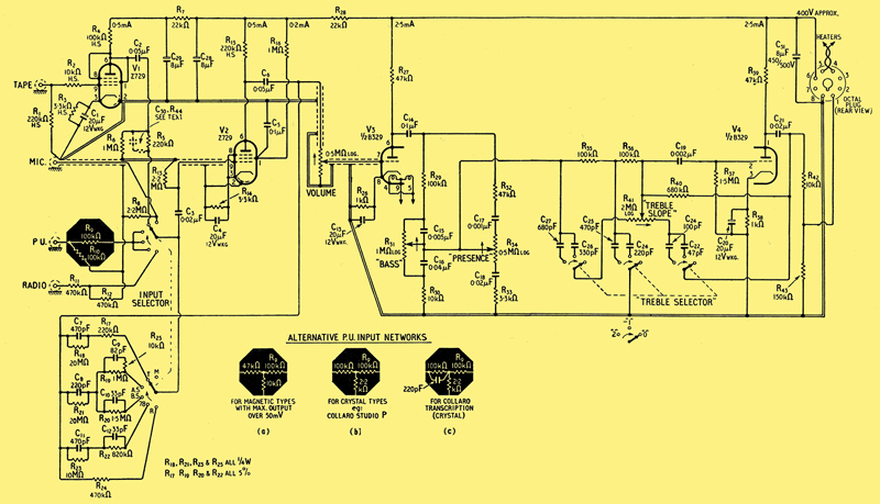
Fig. 1. Circuit of 88-50 pre-amplifier. C7-C12, C22-C27 are silvered mica ±5%. Resistors 0.25 W, 10% unless marked H/S when high-stability type, ±5%. Arrows indicate clockwise rotation of controls. The valves used are Z729 (EF86) & B329 (12AU7).
The first stage of the basic pre-amplifier uses a Z729 valve (V2 in Fig. 1), connected as a pentode. This valve was chosen because its freedom from both hum and microphony are essential to obtain a good signal-to-noise ratio. To keep circuit noise low the cathode current is low, and a voltage gain of about 100 (40dB) is obtained. This is sufficient to give without feedback a sensitivity at the grid of 1 mV, which is ideal for use with a high-impedance microphone such as a diaphragm-operated crystal type, or for use with a moving-coil microphone and a suitable input transformer. For larger input voltages, such as from a radio tuner, the sensitivity can be reduced by negative feedback, and this has the advantage of maintaining the harmonic distortion in the valve at a low level. Between these two extremes any sensitivity can be obtained, and for use with a magnetic gramophone pickup, for example, the necessary frequency response correction to obtain a flat response can be obtained by means of a suitable resistance-capacitance network in the feedback loop, provided the overall correction required is less than the gain of the valve (40dB).
The input selector switch associated with this valve (V2) connects the grid to any of the input sockets, via a suitable network, and simultaneously inserts an appropriate network in the feedback loop between anode and grid. For example, for microphone no feedback is used, and the input resistance consists of R8 in parallel with the grid leak R13. For radio the gain is reduced by negative feedback provided by R24 and R12, and the input resistance is R11.
The other positions of the switch provide the frequency response corrections necessary when playing from disc or tape recordings, and from all the input sources a flat response of roughly similar level is therefore obtained at the volume control which follows this stage. The prototype pre-amplifier shown here has six input positions. The play-back characteristics chosen were considered to be the most useful half-dozen for general use, but alterations and additions are obviously possible where requirements are different. In clockwise order of rotation the bass and treble turn-over points are shown in the accompanying table, which also gives for each switch position the sensitivity and input resistance at the input socket.
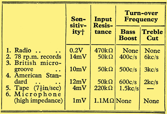
†Input for 0.5 volts RMS output from pre-amplifier.
Tape Compensation
In the tape position the grid of the Z729 pentode is connected to a tape head amplifier consisting of a Z729, triode connected (V1). This gives the best signal-to-noise ratio possible, and raises the signal level to a sufficient level to drive the correction stage, V2.
If tape is not to be played the tape head amplifier can be omitted and the spare position on the selector switch used for another record characteristic, or for a low-impedance microphone. In the latter case a screened microphone input transformer can be mounted in the position previously occupied by the valve.
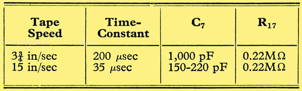
The tape replay characteristic assumes the recommendation that tape should be replayed with a time constant of 100 mS for 7.5 in/sec, and that all treble losses in recording have been compensated by pre-emphasis [3] See Amendment No. 1, July 1954, to B.S. 1968: 1953.. This constitutes a bass boost below 1,500 Hz, see Fig. 4, and is obtained by C7 and R17 in the feedback loop. If tape is to be played at other speeds, then these components must be altered as follows:-
These values could be inserted in other switch positions if more positions are available. The bass boost inherent in these replay characteristics is necessary because the recordings are made with a constant current characteristic, i.e., with a high resistance in series with the recording head, so as to produce a constant flux-density characteristic in the tape. It will be noticed that the replay characteristic levels off at a frequency dependent on tape-speed, and this serves to maintain the treble response.
The use of additional treble boost when replaying to compensate for tape losses is undesirable in so far as it makes tape hiss more audible. However, some treble boost on playback is recommended where a poor treble response is due to the playback head itself, and this can be obtained by shunting R5 by a capacitor C30 of not more than 100 pF for a tape speed of 7.5 in/sec. The effect of this is shown by the dotted curve in Fig. 4. A limiting resistor R44 in series with C30 is desirable of about 100kΩ.
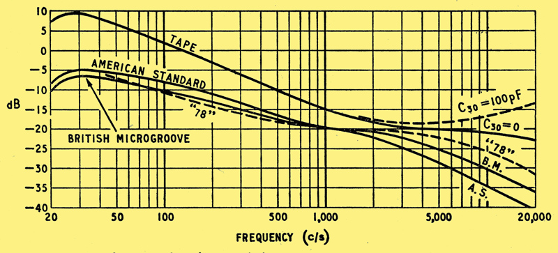
Fig. 4. Disc and tape replay characteristics.
Disc Compensation
The three disc record replay characteristics chosen, see Fig. 4, are the American Standard for both microgroove and 78 RPM discs, the British microgroove characteristic which is tending to be displaced by the American, and a compromise 78 RPM characteristic suitable for most European shellac discs, but most resembling the 'ffrr' characteristic used by Decca and Brunswick. Only those people possessing 78 RPM discs of earlier origin would desire a second 78 RPM switch position giving bass boost from a lower frequency such as 250 Hz.
The bass boost correction for discs is obtained in a similar way to the tape correction, e.g., for American Standard it is obtained by means of C8 and R19, while the necessary treble roll-off is obtained by C9. The limiting resistance R25 is inserted to promote freedom from instability at very high frequecies. In the prototype amplifier it was not found necessary to incorporate limiting resistors in the other compensating circuits. The resistor R21 is connected across C8 to avoid clicks when switching, but it also limits the bass boost correction. If fuller compensation is required between 30 Hz and 60 Hz the value of R21 should be doubled.
The corrections provided here for disc reproduction are intended for use with any pickup giving an output voltage proportional to recorded velocity. This includes all moving-coil and moving-iron (so called 'variable reluctance') types, and the input resistance and sensitivity have been chosen to be suitable for any of the well-known makes with maximum outputs from 10 mV to 50 mV. The input network must be modified however where a pickup is to be used whose output voltage is not proportional to recorded velocity. A crystal pickup is the most common example of this type. It has been found that a very smooth frequency response can be obtained, extending as far as the usual high-frequency peak, if a crystal pickup is connected to an input resistance which is lower than that normally recommended, and the resulting frequency response, which can be made to resemble closely a velocity characteristic, is corrected as if a magnetic pickup were being used.
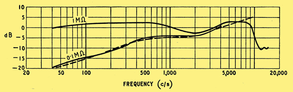
Fig. 5. Velocity characteristic obtained from a crystal pickup, the Collaro Studio 'P' by using a load of 0.1MΩ. Velocity characteristic of record (British micro-groove) is shown dotted.
An example is shown in Fig. 5, where the output from a sample Collaro Studio 'P' crystal cartridge is plotted against frequency using a test record with a British microgroove characteristic. The response with a 1MΩ load approximates to a flat response, and is that which is normally used. The response with 0.1MΩ shows a fall in bass due to the internal capacitance of the crystal unit, and the resulting curve bears a close resemblance to the British microgroove characteristic which is shown dotted. The exact 'fit' of these curves depends on the original response of the pickup, but 0.1MΩ is the most suitable value for several other comparable cartridges. Therefore, with a suitable alteration to the input network, incorporating attenuation of the high output voltage, a crystal pickup can be connected to the pre-amplifier and the corrections associated with the selector switch used as with magnetic pickups. The circuit diagram, Fig. 1, shows an alternative input network, inset (b), enabling crystal pickups of this type to be connected, for example the Collaro Studio 'P'. Inset (c) is suitable for a crystal pickup which has a less pronounced treble peak, the Studio transcription cartridge. Inset (a) is for magnetic pickups having a maximum output greater than 50 mV; note that maximum output is here defined as that given by a recorded velocity of about 7 cm/sec, and corresponds to sections of high modulation on an average disc.
Bass and Presence Controls
The remainder of the pre-amplifier, including all the tone controls, has been economically designed around one double triode. Following the volume control, which is a logarithmic type for smooth control, is the first half (V3) of a B329 valve. This low gain valve is used as a simple triode amplifier without feedback, as this circuit arrangement was found to give the best compromise between distortion and signal-to-noise ratio. It drives a 10:1 (20 dB) potentiometer circuit consisting basically of R29 and R30, in which are incorporated the bass and presence controls. Both these are variable potentiometers of logarithmic law so that the flat response occurs when the knob is at mid-position, and the component values shown are those which gave the flattest mid-position curve in the prototype. For the benefit of those who have the test apparatus and inclination to make accurate adjustments, C16 is the bass boost capacitor and operates when not short circuited by potentiometer R31. Similarly C18 is the treble cut capacitor that gives negative presence when there is no series resistance from potentiometer R34. With both potentiometers upwards, movement of the slider gives increased bass or presence respectively, and corresponds to clockwise rotation.
Treble Controls
From the sliders of the Bass and Presence controls the signal is amplified in a final triode stage, V4. This is the second half of the B329 valve. Negative feedback is employed consisting of feedback resistance R40 in conjunction with stand-off resistors R35 and R36. Associated with these resistances are the treble cut capacitors C22, C23, C24, C25 and the treble boost capacitors C26, C27. These may be switched into circuit by the Treble Selector switch, in which case the amount of cut or boost may be adjusted by potentiometer R41 which is the Treble Slope control. Minimum treble occurs with the slider to the right in the circuit diagram, and this should correspond with a fully clockwise position of the knob if a logarithmic law potentiometer is used. In this position the treble cut has a maximum asymptotic value of 12 dB per octave. If it is desired to increase treble clockwise then an inverse log potentiometer must be used, but this is not so readily available. On the prototype amplifier a flat response was obtained with the knob about 45° from the mid-position, on the boost side, using a logarithmic potentiometer. The Treble Slope control is completely inoperative if the treble selector switch is in the flat position.
Rumble Filter
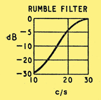
Incorporated within the feed-back loop of V4 are two resistance capacitor coupling networks, C19 R37 and C21 R43, each having a time constant of 0.003 sec. The effect of these is to attenuate low frequencies, while their combined phase shift within the feedback loop makes the feedback positive below 50 Hz. The combined effect is to give a flat response down to 30 Hz below which the response falls steeply to a minimum value, at which frequency (about 15 Hz) the coupling capacitors elsewhere in the amplifier are arranged to provide additional attenuation.
The effect of this rumble filter is shown above. If it is desired to attenuate the low frequencies below 40 Hz instead of 30 Hz then R37 and R43 may be changed to 1 MΩ and 0.1 MΩ respectively.
In addition to its use for the rumble filter the feedback on V4 maintains its output impedance low over most of the frequency range, and the output impedance of the pre-amplifier is therefore approximately equal to R42, about 10 kΩ. Up to 5 feet of ordinary screened cable may therefore be used when connecting to the power amplifier without affecting the high frequency performance.
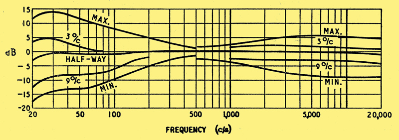
Fig. 2. Frequency response of complete amplifier with Input Selector on Radio, with effect of Bass and Presence controls. Treble Selector at 'O'.
Construction
The construction is novel in that the components are mounted within an open frame, with removable cover plates on both top and bottom This departure from an orthodox chassis simplifies assembly. For example, the switches can easily be wired after mounting. The overall dimensions of the basic chassis are 14 in x 5 in x 2 in, with the control knobs spaced 2.25 in apart. The edges on both top and bottom are flanged, to a minimum width of 0.25 in, so that flat detachable cover plates 14 in x 5 in may be screwed on. In the model photographed hank bushes tapped 6 BA were inserted in the flanges, but self-tapping screws could be used. The spacing of the valves and capacitors along the rear panel is not critical, but 2 in between centres is suitable, leaving 3 in between either end of the chassis and the nearest valve centre line. At the input end this 3 in space has to accommodate the four co-axial input sockets. At the output end a chassis-mounting octal plug is accommodated.
The prototype chassis was constructed with the rear and two ends in one piece of 16 SWG aluminium, and the front section containing the controls was separately made and screwed on. The front escutcheon panel was made separately to mount only on the control bushes, and was slightly larger than the amplifier, 15 in x 3 in.
The 1.75 in tag board contained 44 pairs of tags of which 37.5 were required. It was mounted to leave a space of 2 in from the front and 1.25 in from the rear. The tag board is mounted on a U-section channel 0.75 in x 0.25 in which is bolted to each end panel. A wider tag board, while having no advantages, would necessitate a corresponding increase in the 5-inch dimension of the chassis.
The control switches and potentiometers should be mounted on the front. The input selector is a 2-pole, 6-position switch, each pole being on a separate wafer for ease of wiring and separation of the circuits. More positions may be included if desired, and a correspondingly greater number of tag board spaces allocated. For easy wiring this switch should be mounted with the slider tag of each wafer next the bottom cover plate. A spare insulated tag should be provided on the rear wafer for use as an earth post. The Treble Selector is a 3-pole, 3-position switch on a single wafer.
The B9A valve holders and HT smoothing capacitors should be mounted on the rear, together with the input sockets. These were television aerial input sockets because of their complete screening, and low contact resistance. Jacks may be used where easier plugging is desired, but care must be taken to see that the plugs are of a completely screened all metal construction, to avoid hum pick-up, and that all contact surfaces are clean because the contact pressure is low, and oxidation has been found to cause rectification and distortion of the signal. Valve holders should give a reliable pin contact, and should be of a material that will not give internal tracking on high resistance circuits, e.g., polythene or ceramic rather than a loaded plastic. The valve holders and the octal supply plug should be mounted with the heater pins, 4 and 5, nearest the lower flange of the rear panel.
Wiring
The heater wiring should be completed first. This should be wired in a tightly twisted pair from the octal supply plug, pins 4 and 5, and layed inside the lower flange of the chassis, looping in at each valve holder beginning with the B329, V3/V4, and ending with the tape head amplifier, V1. By this means the wiring to the early stages, V1 and V2, carries only the current to those valves, and this reduces the hum field due to the heater wiring to a minimum. The diversion of the twisted wiring at each valve holder must be kept as short as possible, the valve holder tags being used as junction posts to which the go and return wires are paired together as much as possible. No escutcheon lamp is included in the prototype, and this has enabled all heater wiring to be kept well away from the remainder of the circuit. If a lamp is to be included, it must be wired with a tightly twisted pair directly to the octal supply pins, the wiring must be well separated from the earlier stages, and should preferably be external to the chassis. Neither side of the heater supply is earthed to the pre-amplifier chassis, a centre tap earth being provided near the transformer in the power amplifier.
One earth tag should be screwed to the chassis at the microphone input socket which is the lowest of the three at the end of the rear panel. This is the only chassis connection, apart from the HT smoothing capacitors which need not be insulated from their mountings, but must in any case have their negative tags wired as in Fig. 1. The above earth tag will be found convenient for the insulated braiding of the screened lead which connects the microphone socket to the selector switch, and the tag is also spaced by the length of one resistor R2 from the tape head input socket which is mounted close to the tape head amplifier V1.
The circuit diagram, Fig. 1, indicates how the earthing and other critical wiring is arranged, and this should be closely adhered to. The wiring round V1 should be completed first. The input signal is applied between grid and cathode via the grid stopper R2 and cathode bypass capacitor C1 respectively, and it is important that these two components should be positioned with a very small loop area between them. This will minimize the injection of hum from stray AC magnetic fields, such as from a nearby mains transformer. Accordingly R2 must be wired direct from the input socket to the grid, pin 9, and C1 direct from the earth tag to the cathode pin 3. The grid leak, R1, is wired compactly between the input socket and the earth tag, to which the cathode bias resistor R3 should also be connected. The centre of the valve holder with the earthy pin 2 should be connected by an insulated wire to the earth tag, and the negative tag of the HT smoothing capacitor C28, C29 should be similarly earthed by an insulated wire close to the chassis even if the capacitor case is clamped to chassis. The anode load R4 is connected direct to C29 and the coupling capacitor C2 to the fifth rear tag on the tag board. For minimum circuit noise it is essential that R1, R2, R3 and R4 should be of the high-stability type, and C1 must be of a type having low leakage current.
The wiring of the selector switch and V2 should now be undertaken. The layout of components will be clear from the circuit and photographs, but a description of the earthing arrangements will be given. A short length of screened lead should be wired to the microphone input socket and its earth tag, and the other end of this connected to the sixth contact of the selector switch (rear wafer). The braiding should be connected to a spare insulated tag on the wafer (not connected to the switch frame), and this will act as the sole earthing point of all the input networks. To this earth point is connected the insulated braiding of a second length of screened cable, the inner of which is connected via C3 to the slider of the rear wafer. This cable terminates at the grid, pin 9, of V2, and the insulated braiding carries earth continuity to the earthy Pin 2 of this valve. The cathode bypass, C4 and resistor R14 are soldered compactly across the valve holder between pins 8 and 2 thus giving a very small grid-cathode loop area. This is indicated in the circuit diagram.
The output from V2 is via C6 to the sixteenth rear tag on the board, and the earthing wire of C28, C29 is connected to the seventeenth rear tag. From tags 16 and 17 a short screened lead is taken to the volume control, and from the slider of this a longer screened lead terminates at the grid pin 7 of V3 (B329). The braiding is connected to the earthy pin and the earth line of all the tone control circuits is connected solely to this pin, as also is the octal output plug, pin 8.
The earthing system described above gives continuity from the one chassis connection at the input sockets, via the braiding of screened lead wherever this is used, to the output socket. As the chassis is not used for earth continuity large loop areas between any signal live lead and earth are avoided, and hum pick-up from stray AC fields is reduced. In the early stages the use of screened lead wherever possible reduces loop area to zero, and where open wiring is unavoidable, as in the input selector switch, the close proximity of the earth circuit reduces loop area to a minimum. Only by this means can hum induced electro-magnetically be kept to a minimum, because the enclosure of the circuit by the chassis has no effect on this, although the chassis does provide the necessary electrostatic screening of the live portions of the circuit.
Performance and Operation
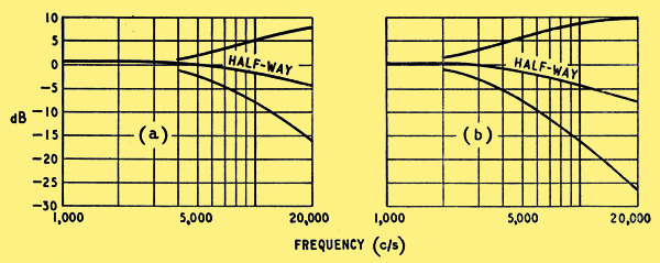
Fig. 3. Effect of Treble Slope control with Treble Selector at -1 (a), and at -2 (b).
The performance of the pre-amplifier is shown in Figs. 2, 3 and 4. The steep fall in frequency response below 30 Hz shown in Fig. 2 is due to the rumble filter, and the effect of this applies to all inputs.
The Bass control (Fig. 2) increases or reduces the bass at frequencies below 300 Hz, and should be used when the volume control is set to reproduce speech or music at a level which is unnatural compared with the original. For example, speech reproduced above its natural level will sound too heavy in the bass, and the bass loudness should be reduced to restore naturalness. Further reduction of bass is often necessary for public address purposes to improve intelligibility. Music, on the other hand, when reproduced at a level producing less than the original loudness at the ear, sounds lacking in bass and the bass loudness should be increased to restore a more normal balance.
The Presence control (Fig. 2) alters the level of all frequencies above about 1,500 Hz. It therefore alters the balance between high and low frequencies; an increase in Presence giving a more forward incisive quality as if moving the listener nearer to the orchestra or voice. A decrease appears to move the listener farther away, and approximates to the effect of sitting at the back of a concert or dance hall.
The two treble controls are intended to be used together for the control of distortion or deficiencies in the programme material above 6 kHz or 3 kHz. The Treble Slope control operates above either of these two frequencies depending on whether the Treble Selector is switched to -1 or -2 respectively. A maximum attenuation slope approaching 12 dB. per octave is available at one end of the Treble Slope control, this changing smoothly through a substantially flat response to a boost at the other end of nominally 6 dB per octave. The 6 kHz position is useful for correcting reproduction from tape or microgroove disc recordings. The 3 kHz position is useful for 78 RPM shellac discs or tape at 3.75 in/sec.
If the Treble Selector is switched to flat, a level response is obtained and the Treble Slope control is rendered inoperative.
The component values have been chosen so that if the pointers on the knobs are arranged symmetrically with respect to the maximum and minimum positions, then with all knobs vertical, i.e., half-way round, a flat response is obtained. This arrangement can be seen in the photograph of the front panel, Fig. 1 of the previous article (reproduced below), and forms a convenient reference for using the controls. With the Treble Slope vertical slight treble cut is obtained as soon as the Treble Selector is moved off the flat position.
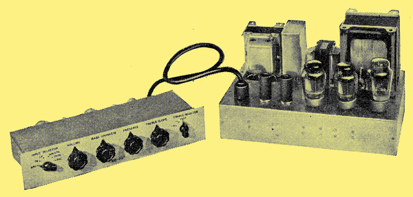
General view of the '88-50' amplifier with (left) its complementary pre-amplifier.
The power amplifier already described requires 0.5 Volts RMS input to drive it to its maximum power output of 50 Watts. The pre-amplifier will deliver this voltage, 0.5 Volt, at a harmonic distortion comparable with that of the power amplifier. This level of distortion does not deteriorate with variation of the controls, given a programme of reasonably normal balance, and this is assured by the Input Selector circuits. To avoid a distortion contribution from the stage V2 before the volume control, all input levels must be adjusted so that full power (50 Watts) is not obtained until the volume control is beyond the half-way (vertical) position. This means that an increase of input level nearly 20 dB above the minimum can be accepted without additional distortion.
The pre-amplifier derives its power supplies from the 88-50 power amplifier, and the smoothing in the HT supply is chosen to be the minimum required for ripple attenuation, so as to give as high an HT line voltage in the pre-amplifier as possible. No HT decoupling, additional to the above, is required for stability because the stabilization circuits in the power amplifier, together with its pure push-pull driver circuit, contribute greatly to its freedom from instability at very low frequencies.
The signal-to-noise ratio of the complete amplifier, relative to 50 Watts, is -76 dB, with the volume at minimum and controls flat (vertical). With the input sockets short-circuited and the volume control at maximum the following signal-to-noise ratios were measured on the prototype: radio, -69 dB; American Standard disc replay, -63 dB; tape replay, -52 dB; microphone, -55 dB. To achieve these figures when the amplifier is installed in a cabinet all input cables should be of the screened variety, and care must be taken to avoid placing the pre-amplifier too near mains transformers, gramophone motors, etc., and mains supply leads within the cabinet should everywhere be in the form of a twisted pair.
The chassis of the pre-amplifier must not be metallically connected to the chassis of the power amplifier, except via the octal plugs, because the resulting loop would introduce hum. This means that where a metal cabinet is to be used, the front escutcheon panel of the pre-amplifier must be of insulating material. If this is not possible, the input sockets and earth tag (see Fig. 1) must be insulated from the chassis, which must then be separately connected to the power amplifier chassis by a spare pin on the octal plug. It is usually necessary to earth the installation, and to avoid loops this must be at one point only, the third pin on the mains supply being suitable in most cases.
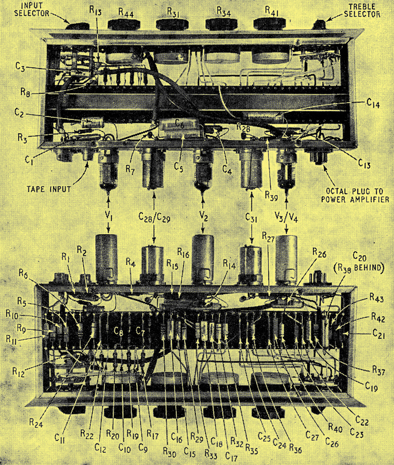
Top and underside views of chassis with covers removed to show layout of principal components.
Footnotes
- Research Laboratories of the General Electric Co., Ltd.
- In the 1950's the unit was cycles per second or c/s
- See Amendment No. 1, July 1954, to B.S. 1968: 1953.
|
