|
General view of the '88-50' amplifier with (left) its complementary pre-amplifier. Small signal valves are B339 (12AX7) and B329 (12AU7).
For many years the KT66 valve has been regarded by many as the hall-mark of a high-quality amplifier whether home made or commercially manufactured. With a total anode-plus-screen dissipation of 28 Watts, when operated with cathode bias, its power output, in push-pull pairs, ranges from the 12 Watts of the original Williamson amplifier, to 32 Watts when used in an ultra-linear output stage.
The new KT88 is a pentode with a higher anode-plus-screen dissipation of 40 Watts, and a higher mutual conductance of 11 mA/V. With this valve it is therefore possible to build amplifiers having higher power outputs suitable for public-address equipment and high-quality sound reproduction in general. Due to the lower anode impedance of the new valve, its higher power output is obtained without increasing the HT voltage requirements beyond the limits of normally available components. For example if plugged into a KT66 ultra-linear output stage giving 32 Watts, a pair of the new KT88 valves will give 40 Watts with a corresponding increase in drive voltage. Thirty watts output is obtainable with a HT line voltage of only 375 Volts, instead of 425 Volts for the KT66.
The maximum power obtainable from a pair of KT88s with cathode bias is slightly over 50 Watts with a HT line voltage of 500 Volts. This article gives details of the design and construction of a 50 Watt power amplifier using KT88s. A new pre-amplifier suitable for use with this amplifier will be described later.
The two units have been designed to offer an improved performance and range of controls compared with previous designs, yet they include no complicated networks or unusual components, and are comparatively economical to construct. They will reproduce from radio tuner, any magnetic (or crystal) gramophone pickup, microphone, or direct from a magnetic tape replay head. A rotary switch selects the input circuit required and at the same time adjusts the sensitivity and frequency correction for tape or disc recordings. The pre-amplifier is separate from the power amplifier to which it is connected by a flexible cable; its controls are similar in function to those on the GEC 912 amplifier, but the operation of the treble slope and presence controls has been improved, and a rumble filter is incorporated.
Power Amplifier
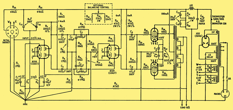
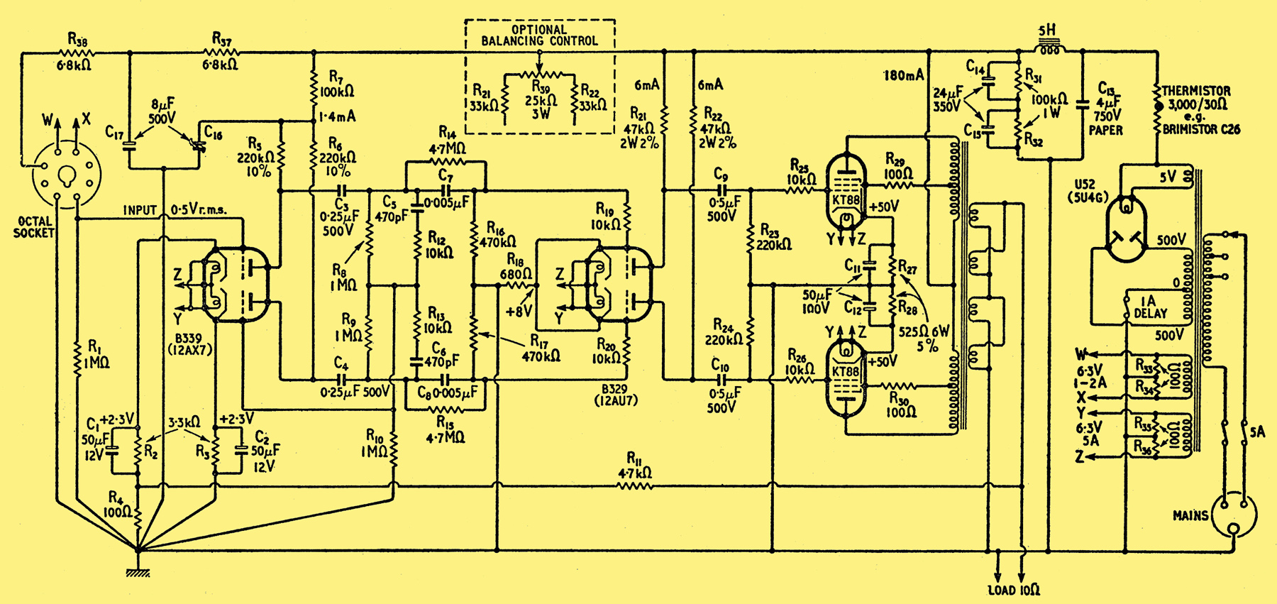
Fig. 1. Complete circuit diagram of the main amplifier. Resistors are rated at 0.5W unless otherwise stated.
The circuit of the power amplifier is shown in Fig. 1. It contains a pair of KT88s connected in an ultra-linear output stage, a push-pull low-impedance double-triode driver stage using a B329, and a high-gain B339 first stage incorporating phase splitting. Overall feedback of -22 dB is used, and the input sensitivity is about 0.5V RMS to give full output power. The 500 Volt HT supply is provided by a U52, and the electrolytic smoothing capacitors are protected by the use of a thermistor against excessive voltage during the warming-up period.
The ultra-linear connection for output tetrodes and pentodes has become popular during the past two years. As will be seen from Fig. 1, it resembles the triode connection except that the screen grids are tapped down the primary winding of the output transformer and the signal voltage on each screen is only 20 per cent to 40 per cent of the signal voltage in the corresponding anode [3] Either ratio is satisfactory, but with 40% screen tappings it is easier to design an output transformer giving freedom from instability at very high frequencies. Its advantages are that it gives a maximum power output at least equal to that obtained from the pentode connection, with distortion similar to or less than that for the triode connection, which gives less than half the power output. For equal power output, the distortion from an ultra-linear output stage is about half that for a triode stage using the same valves. The ultra-linear connection also provides a low output impedance, roughly equal to the load, and a good damping factor is, therefore, easily obtain- able when feedback is applied. A push-pull output transformer is required which has each half primary tapped 40 per cent (turns ratio) from the HT end. Leakage and inductance requirements are discussed later.
The use of a push-pull pair of triodes for the driver stage was chosen so that the output stage would be symmetrically driven, and that no unbalanced operation would occur even at the onset of grid current in the output valves during overload. The removal of the phase splitter to an earlier stage ensures that the time constants in the grid circuits of the output valves are the same. The B329 is used in this stage because it has a low anode impedance, about 10,000 Ohms. With this low value of driver impedance the phase shift due to the input capacity of the output stage is relegated to frequencies above 50 kHz, and this, combined with the symmetry of the circuit, greatly assists in ensuring freedom from HF instability when feedback is applied overall.
A high-gain first stage (B339) is used to provide good balance in the phase-splitting circuit, and also adequate overall sensitivity after feedback is applied: the phase-splitter circuit used is one in which the input to the grid of the second or inverter triode is automatically balanced against its stage gain. This circuit gives a push-pull output from the two anodes of the B339, and as the amplifier is truly push-pull from this stage through to the output transformer little h.t. smoothing is required, with a corresponding economy in components.
Balancing Circuits
The push-pull output from the B339 stage is balanced to about 2 per cent, a high-gain stage being an advantage here. This balance is improved slightly by the use of an un-bypassed common bias resistor in the cathode circuit of the B329 driven stage. This degree of balance is very satisfactory for many purposes, and with close-tolerance cathode bias resistors the KT88 valves used in designing the prototype amplifier have given a consistently symmetrical output voltage waveform when driven up to full power output when the peaks just show flattening due to the onset of grid current. However, it has been found on amplifiers of this type with unmatched output valves that minimum distortion is obtained when the push-pull drive is adjusted so that both output valves reach the onset of grid current simultaneously as the drive voltage is increased.
Where facilities are available, and it is desired to make this adjustment, alteration of the balance of the push-pull drive is obtainable by relative adjustment of the two anode loads of the B329, and accordingly a pre-set variable wire-wound potentiometer R3, is shown in Fig. 1 incorporated as part of the anode loads circuit. The waveform of the voltage across the secondary of the output transformer can be observed on a cathode-ray oscilloscope connected across a dummy load resistance, and R3, should be adjusted so that with a sinusoidal the input voltage of suitable value the output waveform shows similar flattening on both positive and negative peaks. Although judged visually, this adjustment can be made with more than sufficient accuracy, provided the input waveform is free of second harmonic distortion. To avoid phase effects a frequency is chosen between 200 and 2,000Hz.
Stabilizing Circuits
When feedback is to be applied over an amplifier it is desirable that it is truly negative feedback over the whole frequency range that will be fed to the amplifier. At frequencies outside this range the feedback should be either negative or inoperative. If this is not so, the final frequency response of the amplifier will show peaks. Further increase of feedback, or in borderline cases certain types of input signal, will produce oscillation at these peak frequencies. Even if oscillation does not occur the amplifier will ring at these frequencies; that is, when an input signal containing the peak frequencies is interrupted the output from the amplifier will not cease as abruptly as the input, the peak frequencies persisting, with a more gradually decaying amplitude. The peak frequencies usually occur at very low or very high frequencies, and are due to phase shifts in the inter-valve coupling circuits and in the output transformer itself.
The low-frequency peak occurs only when feedback is applied, and is due to the combined phase shift of the inter-valve coupling capacitors in conjunction with the associated grid leaks, together with the phase shift of the output transformers primary inductance in conjunction with the load and valve impedances. The peak in amplification commonly occurs well below 20 Hz and often results in low-frequency instability (motor-boating) when a pre-amplifier is connected to the same HT power supply. The effect is reduced if the several phase shifts are arranged to occur at differing frequencies, for example in the circuit of Fig. 1, large coupling capacitors are used so that phase shift due to them will occur at frequencies lower than that due to the output transformer.
Complete or nearly complete avoidance of a low-frequency peak can best be obtained by reducing the gain of the amplifier before feedback is applied at the frequency at which the peak is expected, without introducing additional phase shift at this frequency. If a flat frequency response is required down to this frequency, then the reduction in gain should approximately equal the feedback to be applied. This is achieved by inserting a small coupling capacitor shunted by a high resistor, so that with the following grid leak the gain is reduced as the signal frequency is lowered until at the very low frequencies where a peak is expected the gain is reduced by a substantially resistive potential divider with very little phase shift. For a 20 dB (10:1) gain reduction the shunt resistance should be ten-times the grid leak. The capacitor should be sufficiently small to have an impedance at the very low frequencies equal to or higher than the shunt resistance.
As the 88-50 amplifier is push-pull throughout such a circuit has to be incorporated on each side, and on one side, in Fig. 1, this consists of C7 shunted by R14 and followed by grid leak R16 with C8, R15 and R17, on the other. The valves chosen will give low-frequency stability with any output transformer capable of delivering the full power output down to 40 Hz. An advantage of the inclusion of this type of stabilizing circuit is that there is no tendency for the amplifier to motor-boat when the pre-amplifier is connected to the same HT line. The smoothing used in the pre-amplifier supply is therefore economically chosen solely to give sufficient ripple reduction.
At the high frequencies peaks may be detected in the response of most amplifiers when this is measured up to 100 kHz or 200 kHz before feedback is applied. These peaks are due to resonances in the output transformer, the most important of which is the series resonance of the primary leakage inductance with the primary winding capacitance. This is commonly the cause of the first peak, i.e., of lowest frequency. The response usually shows a general downward trend, and this is due to the total shunt capacities, including Miller effect, across each anode load in the amplifier. When feedback is applied the combined phase shifts due to shunt capacities and leakage inductance cause the peaks in the response to be exaggerated, and often rise above the mid-frequency level.
With the output transformers used in designing the prototype 88-50 amplifier the leakage inductances between the several windings were low, as described later, and the first high-frequency peak was detected about 100 kHz. Accordingly a stabilizing circuit, similar in principle to that used at the low frequencies, is incorporated. This consists of a shunt capacitor connected across the anode impedance of the first valve, with a series resistance to limit its shunting effect to about 20 dB (10:1) and minimize phase shift at frequencies above 50 kHz. In Fig. 1 this circuit consists of C5 with R12, in series, and on the other side of the amplifier C6 with R13, in series. These values are sufficient to give stability when the amplifier is loaded capacitively, and to reduce ringing on a square wave input (10 kHz repetition rate) to only about 10 per cent overshoot on a resistive load, and even less on an inductive load.
The use of capacitors for improving stability across any portion of the output transformer is not recommended in presence of the above stabilizing circuits, and was found merely to lower the resonant frequency, which was undesirable, and in some cases increased overshoot. The use of such capacitors depends on individual transformer design, and is not suitable in this context. No reactances giving phase correction are included in the feedback network itself (R11, and R4) because the correct choice of reactance is critically dependent on the type of load and output transformer used. For example overshoot, or actual instability, using a given transformer and dummy load resistance can be greatly reduced by shunting the feedback resistance R11, by a critically chosen value of capacitance, but this will be found to worsen stability on a reactive load such as a loudspeaker. This behaviour is common to all feedback amplifiers, and the stabilizing circuits here incorporated within the amplifier itself give satisfactory results with a wide variety of loads, and with the several transformers used in testing the prototype.
Greater stability could be obtained with inferior output transformers by altering the capacitances in the stabilizing circuits so that the level frequency response of the amplifier, before feedback is applied, is further restricted. The level frequency response at high and low frequencies will be restored when negative feedback is applied, but the amount of feedback (difference in gain with and without feedback) will be so reduced that the overall harmonic distortion at high and low frequencies will be considerably higher than at mid-frequencies. In addition the valve preceding the stabilizing circuits handles a higher signal voltage at high and low frequencies, and extra distortion may occur here as well as the distortion inherent in using a poorer output transformer.
The stabilizing circuits shown in Fig. 1 are incorporated in as early a stage as possible, so that only one valve precedes them within the feedback chain. The components values have been found satisfactory for use with a typical minimum transformer, but are primarily intended for use with a transformer of the type described below. The reduction of feedback at 40 Hz and at 10 kHz amounts to some 6dB less than the -22 dB feedback at mid-frequencies.
Output Transformer
The output transformer used for the first prototype amplifier was the type WO866, made by R F Gilson, Ltd. Although originally intended for operation with valves of lower power output, it gives a very good account of itself with the KT88 from 40 Hz to 20,000 Hz. Another transformer tried with excellent results was the Savage Type 4N1. For its extra size and cost this would deliver the full power output down to a lower frequency than the WO866.
The requirements for an ultra-linear transformer to be used with feedback are adequate primary inductance and low leakage inductances between primary and secondary (as normally connected), between each half primary, and between each half primary (anode-tapping) and the associated screen tapping. The primary winding capacitance must also be low enough to relegate the lowest high-frequency resonance to the region where a reasonable stabilizing circuit has reduced the gain of the amplifier without appreciable phase shift.
Both the transformers mentioned gave measurements of all five leakage inductances less than 6 mH, and a high-frequency resonance in circuit operation above 100 kHz. The WO866 achieves this by the use of gain-oriented silicon iron, with moderate sectionalization of the windings, and the 4N1 achieves similar figures with a larger core of normal silicon iron by more sectionalization of the windings.
Construction
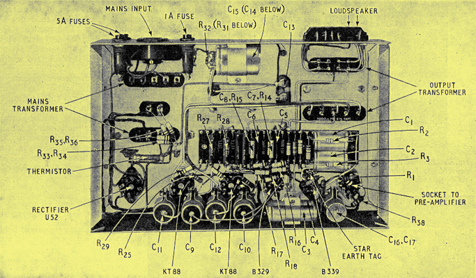
Underside of chassis showing layout of principal components.
The accompanying photograph shows the underside of the power amplifier chassis. The prototype was constructed on a chassis measuring 14in x 9in x 3in. The mains transformer was of ordinary silicon iron, but the choke and output transformer were of grain-oriented silicon iron and were therefore comparatively small. A slightly larger chassis would be needed if larger transformers were used, but the same layout must be used, and the transformers positioned as in the top view of the amplifier. Because of the high HT voltages it is advisable to mount the transformers tags down; the elongated holes required can easily be cut with a valve hole-cutter and file.
The heater wiring should be laid in first, with twisted twin wires laid along the bend of the chassis. The valve-holders are oriented to avoid the heater wires crossing the grid wiring. The second heater supply to the octal pre-amplifier socket connection should also be laid in. Both supplies must have a centre-tap earthed to chassis, or an artificial centre-tap using two equal resistances, as shown. An earth point should be chosen next the first valve B339, and a star tag bolted down with a serrated washer to ensure good contact. This will be the one earth point to which all grid, anode, and inter-valve coupling circuits must be connected by insulated wiring. The signal input (pin 8 on the octal socket) should be wired as directly as possible to the grid of the first valve; the earth (pin 1 on the octal) connected to the star earth tag, and the grid leak connected. The cathode bypass capacitor with feedback resistance R4, in series should be connected between the cathode pin and the star earth tag using the smallest total loop area of wiring possible, and keeping the cathode circuit as close to the grid input lead as possible. The cathode bypass capacitor of the second half of the B339 should be wired in an equally compact fashion. The grid of this valve is fed from the phase-splitting network connected between the two anodes, and this should be wired as compactly as possible consistent with good mechanical location of the components.
The tag-board is used for all the smaller components, but the larger coupling capacitors and the later cathode bypass capacitors are mounted by standard clips on the side of the chassis. Except for C14 the clips earth the capacitor cases, which thus provide screening. For ease of servicing almost no wiring is beneath the tag-board.
Wiring should be continued by working through the amplifier, keeping grid and anode wiring as short and as separated as possible, while dead wiring such as HT leads returning to a smoothing capacitor, or cathode bias resistors which are bypassed, may be longer to fit in. Stopper resistors R19, R20, R25, R26, R29, and R30 are included to kill instability at radio frequencies, and must be wired closely on the valve-holders with very short leads. Stoppers are unnecessary in the grids of the B339.
The earth connecting point associated with each valve should be insulated, and connected back to the insulated earth point of the preceding valve, and so to the original star earth tag. The earthed side of the secondary of the output transformer should also be returned to this tag as this is part of the feedback circuit. An exception may be made of the HT supply earth, and the heater supply centre tap earths, which can be connected to any convenient points in the chassis.
The mains transformer is as remote as possible from the input to discourage hum, and its orientation should be noted. The output transformer is of necessity nearer the input, and the live anode and screen wiring to it should be bound together and laid carefully away from the tag-board and other components.
Using the precautions outlined above the strip layout of this amplifier gives the greatest separation of input and output and the least potential teething troubles.
Connecting the Feedback
When completed and checked, a dummy resistance load should be connected, and first switched on with the feedback disconnected by an open circuit at R11. If the voltages measured across the cathode bias resistors approximate to those shown in Fig. 1 (some voltmeters will give a lower reading) a test signal may then be connected to the input of about 100 mV, and a loudspeaker tapped across the dummy load. If an audio oscillator is not available, a gramophone pickup having a high output, such as a crystal type, can be connected to the input via a temporary volume control. An extra resistance of about 47 kΩ should be connected in series with R11.
With the test signal audible, the feedback should be connected, and a note made of whether the output is increased or decreased. If the feedback increases the output the connections to the output transformer must be reversed. If the feedback decreases the output then the connections are correct, and the feedback may be permanently connected with the extra resistance removed. This method removes the risk of oscillation and possible damage to the output valves and transformer.
Performance
The maximum power output of an R-C coupled amplifier such as that described here may be conservatively defined as the maximum obtainable without driving the output valves to grid current. This criterion is easily checked on a cathode-ray oscilloscope, the onset of grid current being observed as peak clipping, the input being reduced just to avoid this. The measurements described below use this method of determining maximum power output.
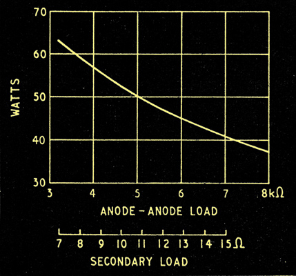
Fig. 2. Maximum power output of KT88 output stage delivered to load on secondary of transformer (Gilson WO866), at 500 Hz.
Fig. 2 shows the maximum power output, measured across various values of dummy load resistance on the secondary of the WO866 transformer. An output of 50 Watts is obtained in the load with an equivalent anode-to-anode load of 5,000 Ohms, which corresponds with this transformer to a load resistance of 10.7 Ohms. These conditions were used for subsequent tests.
It, should be noted that values of anode-to-anode load below 4,000 Ohms give increased distortion and are not recommended. The WO866 transformer has a ratio which gives a primary load of 7,000 Ohms for a 15 Ohm secondary load, and satisfactory operation can be obtained when operating into one 15 Ohm loudspeaker giving about 40 Watts maximum output, or into two 15 Ohm loudspeakers connected in parallel giving about 60 Watts at somewhat greater distortion. At frequencies above and below 500 Hz the impedance of a loudspeaker, or loudspeaker assembly, is usually greater than the nominal value, and the effective load is therefore higher.
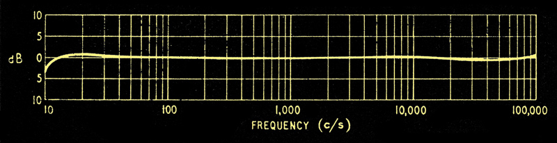
Fig. 3. Frequency response of power amplifier measured at 1 Watt output.
Fig. 3 shows the frequency response at a power output of about 1 Watt into a load of 10.7 Ohms. The level response with the absence of peaks over the whole frequency range from 10 Hz to 100 kHz indicates that the stabilizing circuits are very satisfactory with an output transformer having the characteristics described earlier. In consequence the amplifier is completely free of any tendency to parasitic oscillation under drive. The tendency for the response to fall below 10 Hz is typical of a stabilized amplifier with feedback, and greatly assists LF stability when a pre-amplifier is connected to the same HT supply.
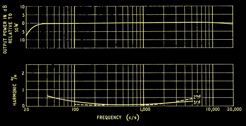
Fig. 4. Maximum available power at different frequencies, and distortion at maximum power output. Transformer: Gilson WO866. Load 10.7 Ohms, equivalent to 5,000 Ohms anode-anode.
Fig. 4 shows that maximum power output is obtainable within 0.5 dB over the audio band from 30 Hz to over 20 kHz. Below 30 Hz this is limited by flux saturation phenomena in the output transformer, rather than by peak clipping in the output valves. At these low frequencies the power at which saturation occurs depends on the unbalanced DC in the transformer primary. This was 2 mA in the amplifier under test with unpicked valves. The power output is maintained to well above 20 kHz because of the low leakage inductances and lack of resonances below 100 kHz in the output transformer.
Fig. 4 also shows the distortion at maximum power, and this is less than 0.1% of the fundamental for both 2nd and 3rd harmonics at 500 Hz. The increases at 100 Hz and 5,000 Hz are due to the reduction of effective feedback at high and low frequencies because of the stabilizing circuits, but this is a small price to pay for the clean performance resulting from good stability. The harmonic distortion was measured up to 15 kHz, and listening tests confirmed the merit of the results shown.
The maximum power output is obtained with an input drive of 0.5 Volts RMS, and the hum level is -73 dB with the input open circuited, or better than -90 dB with the input short circuited. The feedback is -22 dB at 500Hz with the components shown and a 10.7 Ohm secondary (24 Volts output). For use with load impedances other than this the feedback resistance R11, (4.700 Ohms) should be altered in proportion to the resulting output voltage.
The authors wish to record their thanks to their colleague D M Leakey for his considerable help and advice during the design of this amplifier.
Footnotes & References
- Research Laboratories of the General Electric Co., Ltd.
- The MO Valve C0., Ltd.
- Either ratio is satisfactory, but with 40% screen tappings it is easier to design an output transformer giving freedom from instability at very high frequencies.
- Stabilizing Feedback Amplifiers, Thomas Roddam, Wireless World, March, 1951.
- UL Output Transformers, D M Leakey and R B Gilson, Wireless World, January, 1956.
Addendum
The balance of the push-pull out-put from the B339 stage is stated to be about 2%. To achieve this it is necessary for the 1 MΩ resistors R8 and R9 to be equal, and close tolerance values must therefore be used. More nearly perfect balance is obtainable if R9 is about 2% higher in value than R8, and where a comparison meter is available these two resistors can be selected from the available stock, the actual value being unimportant. A good compromise would be to use 5% tolerance for these two resistors, and to use the one of higher value as R9. Apart from the use of 5% tolerance for R8 and R9, the above precautions are necessary in amplifiers incorporating the balance control, R39.
|