|
Recent work on single input series-connected output stages
It seems to be an example of some natural law of cussedness that review articles are rapidly followed by a spate of further publications on the subject; and the article on 'Output Transformerless Amplifiers' (February, 1957, issue, p. 58) has proved no exception. As some of this further work has followed what were only sidelines of the original article, further information is given here, together with notes on other developments.
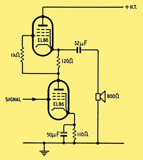
Philips single input series-connected output stage.
The Philips single input series-connected output stage (shown above, based on Fig. 3 on the Feb., 1957, article) has been more fully described. The signal input for the upper valve already contains second-harmonic distortion produced by the lower. This will give second harmonic in the upper valve by amplification, and this will be out of phase with the second harmonic produced by distortion in the upper valve. The signal input for the upper valve is out of phase with that for the lower as it is produced by amplification in the lower valve. Thus the second harmonic distortions generated by the valves themselves tend to cancel in the load, as in a push-pull stage. The second harmonic conveyed to the load by amplification in the upper valve can then only be cancelled as well if the upper valve contributes more out-of-phase second harmonic distortion. One way of achieving this is to decrease the distortion produced by the lower valve by using an un-bypassed cathode bias resistor to give current feedback. However, this increases the output impedance and necessitates a higher input voltage. It is better to shift the working point of the upper valve in the direction of increased distortion by altering the value of the cathode bias resistor, although this gives exact compensation at only one value of the output. In practice it was found that this adjustment of the working point was only critical for low outputs. Using two EL86s and no feedback, 9 Watts output at 10% total distortion was obtained. This distortion included 8% third harmonic and 6% second harmonic. Results are also given in [1] Single-Ended Push-Pull Output Stages, Electronic Applications Bulletin, Vol. 17, No. 3, May 1957, p. 81. for the cases when the current of either or both EL86 valves is 25% less or greater than the rated value. The output impedance of this type of circuit is lower than that for the two valves in parallel because the upper valve operates rather like a cathode follower in which only part of the output is fed back.
The two versions of this circuit with one of the output pentodes replaced by a triode are also analysed in [1] Single-Ended Push-Pull Output Stages, Electronic Applications Bulletin, Vol. 17, No. 3, May 1957, p. 81.. The maximum output power is obtained when the contribution from the triode is very small or zero. The performance is however then inferior to that of a single Class-A operated pentode, both as regards output power and distortion.
Circuits similar to that above have also been described in [2] V S Cooper, Shunt-Regulated Amplifiers, Wireless Engineer, Vol. 28, No. 5, May 1951, p. 132. and [3] G E Valley and H Wallman, Vacuum Tube Amplifiers, MIT Radiation Laboratory Series, Vol. 18, pp. 432-439 (McGraw-Hill).. In [2] V S Cooper, Shunt-Regulated Amplifiers, Wireless Engineer, Vol. 28, No. 5, May 1951, p. 132. it is used as the basis of a high-level, video-frequency modulator. In this application the load is very non-linear as it consists of a capacity in parallel with an effective resistance determined by the grid current in the following stage, ie, a resistance varying with the output level. In [3] G E Valley and H Wallman, Vacuum Tube Amplifiers, MIT Radiation Laboratory Series, Vol. 18, pp. 432-439 (McGraw-Hill). the upper valve is used to provide a high effective resistance to increase the gain of the pentode lower valve.
An analysis of various types of phase inverter connected as in Figs. 7, 8 and 9 of the February, 1957, article with emphasis on obtaining equal drive in the output valves independent of the value of the load has been published by Amemiya [4] H Amemiya, Analyses of Drivers for Single-Ended Push-Pull Stage, IRE Trans, Audio, Vol. AU-3 No. 5, Sept.-Oct. 1955, p. 162.. [4] H Amemiya, Analyses of Drivers for Single-Ended Push-Pull Stage, IRE Trans, Audio, Vol. AU-3 No. 5, Sept.-Oct. 1955, p. 162. also shows how in the Coulter circuit (Fig. 8 of the Feb., 1957, article) the drive in the output valves can be made independent of the load value by choosing suitable values for the feedback fraction and the fraction of the input fed to the phase inverter.
Peterson-Sinclair Circuits
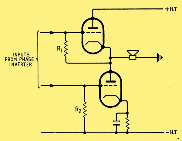
Peterson-Sinclair output stage.
The Peterson-Sinclair output stage [5] A Peterson and D B Sinclair, A Single-ended Push-pull Audio Amplifier, Proc IRE, Vol. 40, January 1952, p. 7. (shown above, based on Fig. 9 of the Feb., 1957, article) has been analysed by several authors [1] Single-Ended Push-Pull Output Stages, Electronic Applications Bulletin, Vol. 17, No. 3, May 1957, p. 81. [4] H Amemiya, Analyses of Drivers for Single-Ended Push-Pull Stage, IRE Trans, Audio, Vol. AU-3 No. 5, Sept.-Oct. 1955, p. 162. [6] C Yeh, Analysis of a Single-Ended Push-Pull Audio Amplifier, Proc IRE, Vol. 41, No. 6, June 1953, p. 743. [7] H Amemiya, The Extended Cathode-Coupled Phase Inverter and its Application to Single-Ended Push-Pull Amplifiers, Jnl AES, Vol. 3, No. 2, April 1955, p. 82 & [8] H Amemiya, An Output Transformerless Amplifier, Jnl AES, Vol. 4, No. 2, April 1956, p. 72.. References [4] H Amemiya, Analyses of Drivers for Single-Ended Push-Pull Stage, IRE Trans, Audio, Vol. AU-3 No. 5, Sept.-Oct. 1955, p. 162. [6] C Yeh, Analysis of a Single-Ended Push-Pull Audio Amplifier, Proc IRE, Vol. 41, No. 6, June 1953, p. 743. [7] H Amemiya, The Extended Cathode-Coupled Phase Inverter and its Application to Single-Ended Push-Pull Amplifiers, Jnl AES, Vol. 3, No. 2, April 1955, p. 82 & [8] H Amemiya, An Output Transformerless Amplifier, Jnl AES, Vol. 4, No. 2, April 1956, p. 72. emphasizing methods of obtaining equal drive in the output valves independently of the load. [6] C Yeh, Analysis of a Single-Ended Push-Pull Audio Amplifier, Proc IRE, Vol. 41, No. 6, June 1953, p. 743. also discusses the optimum valve and operating parameters. [1] Single-Ended Push-Pull Output Stages, Electronic Applications Bulletin, Vol. 17, No. 3, May 1957, p. 81. points out that if tetrodes or pentodes are used for the output valves, then the anode current for the lower will exceed that for the upper by the screen grid current, so that the operating points for the two valves will not be identical. Bypassing the lower valve by a suitable resistor will compensate for this unbalance, though strictly only for one value of the output power.
The effect of the feedback via the anode voltage of the phase inverter in the Peterson-Sinclair output stage is calculated in [1] Single-Ended Push-Pull Output Stages, Electronic Applications Bulletin, Vol. 17, No. 3, May 1957, p. 81. & [6] C Yeh, Analysis of a Single-Ended Push-Pull Audio Amplifier, Proc IRE, Vol. 41, No. 6, June 1953, p. 743. According to the former, the reduction in the distortion is only slight and considerably less than the reduction in the output impedance. In one practical case the reduction ratios were 1.07 and 6.6 respectively.
The effect of the stray capacity at the upper phase inverter load R1, is also calculated by Yeh [6] C Yeh, Analysis of a Single-Ended Push-Pull Audio Amplifier, Proc IRE, Vol. 41, No. 6, June 1953, p. 743.. As pointed out by Peterson and Sinclair [5] A Peterson and D B Sinclair, A Single-ended Push-pull Audio Amplifier, Proc IRE, Vol. 40, January 1952, p. 7., because this load is connected in series with the output, this stray capacity is effectively multiplied by one plus the gain in the output stage, much as in the Miller effect. This effect does not occur at the lower phase-inverter load R2, so that there is some unbalance at high frequencies. In the region where the gain is not affected by phase shift, this can obviously be compensated for by putting an equal effective capacity across the lower phase-inverter load. This was done in practical amplifiers described in [1] Single-Ended Push-Pull Output Stages, Electronic Applications Bulletin, Vol. 17, No. 3, May 1957, p. 81. & [8] H Amemiya, An Output Transformerless Amplifier, Jnl AES, Vol. 4, No. 2, April 1956, p. 72.. In [1] Single-Ended Push-Pull Output Stages, Electronic Applications Bulletin, Vol. 17, No. 3, May 1957, p. 81., with no feedback, the response was only 3 dB down at 650 kHz using two EL86s as output valves and half an ECC83 as phase inverter. Figures for the variation of the distortion in this circuit with load value, power output and supply voltage are also given in [1] Single-Ended Push-Pull Output Stages, Electronic Applications Bulletin, Vol. 17, No. 3, May 1957, p. 81.. The distortion appears to fall just before full output. In the amplifier described in [8] H Amemiya, An Output Transformerless Amplifier, Jnl AES, Vol. 4, No. 2, April 1956, p. 72., using two triode connected 50L6s as output valves and a 6SN7 as cathode-coupled phase inverter, the frequency response was 3 dB down at about 200 kHz with 20 dB overall feedback. 3 Watts with 0.7% inter-modulation distortion were obtained in a 600Ω load.
Another Philips practical circuit similar to Fig. 4 of the Feb., 1957, article, but with a more elaborate phase inverter consisting of two cathode-coupled valves in cascade has been described [1] Single-Ended Push-Pull Output Stages, Electronic Applications Bulletin, Vol. 17, No. 3, May 1957, p. 81. [9] J R de Miranda, Audio Amplifiers with Single-Ended Push-Pull Output, Philips Technical Review, Vol. 19, No. 2, 1957, p. 41. [10] J R de Miranda, Versterkers met Direct Gekop-pelde Luidsprekers, Nederlands Radiogenootschap, Vol. 22, No. 1, Jan. 1957, p. 15. & [11] J R de Miranda, Hi-Fi Philosophy from a European Point of View, IRE Trans, Audio, Vol. AU-5, No. 4, July-Aug. 1957, p. 82. The common cathode resistor produces positive feed- back in the phase inverter stage. It is shown in [1] Single-Ended Push-Pull Output Stages, Electronic Applications Bulletin, Vol. 17, No. 3, May 1957, p. 81. & [9] J R de Miranda, Audio Amplifiers with Single-Ended Push-Pull Output, Philips Technical Review, Vol. 19, No. 2, 1957, p. 41. that if this feedback is adjusted so that this stage by itself would be on the verge of instability, then the output stage does not contribute to the total distortion in the amplifier. The whole amplifier can be stabilized with overall negative feedback provided that the output stage and feedback loop do not introduce any undesirable phase-shifts. This proviso can be satisfied much more easily if there is no output transformer. Using two EL86s as output valves to feed an 800Ω load, 10 Watts output with a total harmonic distortion of 0.3% was obtained. The high frequency response was 3 dB down at 250 kHz, and the output impedance only about 20Ω.
References
- Single-Ended Push-Pull Output Stages, Electronic Applications Bulletin, Vol. 17, No. 3, May 1957, p. 81.
- V S Cooper, Shunt-Regulated Amplifiers, Wireless Engineer, Vol. 28, No. 5, May 1951, p. 132.
- G E Valley and H Wallman, Vacuum Tube Amplifiers, MIT Radiation Laboratory Series, Vol. 18, pp. 432-439 (McGraw-Hill).
- H Amemiya, Analyses of Drivers for Single-Ended Push-Pull Stage, IRE Trans, Audio, Vol. AU-3 No. 5, Sept.-Oct. 1955, p. 162.
- A Peterson and D B Sinclair, A Single-ended Push-pull Audio Amplifier, Proc IRE, Vol. 40, January 1952, p. 7.
- C Yeh, Analysis of a Single-Ended Push-Pull Audio Amplifier, Proc IRE, Vol. 41, No. 6, June 1953, p. 743.
- H Amemiya, The Extended Cathode-Coupled Phase Inverter and its Application to Single-Ended Push-Pull Amplifiers, Jnl AES, Vol. 3, No. 2, April 1955, p. 82
- H Amemiya, An Output Transformerless Amplifier, Jnl AES, Vol. 4, No. 2, April 1956, p. 72.
- J R de Miranda, Audio Amplifiers with Single-Ended Push-Pull Output, Philips Technical Review, Vol. 19, No. 2, 1957, p. 41.
- J R de Miranda, Versterkers met Direct Gekop-pelde Luidsprekers, Nederlands Radiogenootschap, Vol. 22, No. 1, Jan. 1957, p. 15.
- J R de Miranda, Hi-Fi Philosophy from a European Point of View, IRE Trans, Audio, Vol. AU-5, No. 4, July-Aug. 1957, p. 82.
- J Futterman, A Practical Commercial Output-Transformerless Amplifier, Jnl AES, Vol. 4, No. 4, October 1956, p. 163.
- L H Light, Feedback Arrangements in Trans-formerless Push-Pull Output Stages, Mullard Tech Comm Vol. 3, No. 24, May 1957, p. 102. Refers to transistor output stages.
|