|
Stability of Ultra Linear Push-Pull Output Stages at High Frequencies
The advantages afforded by the ultra-linear circuit for push-pull output stages have now been well established, but the necessary conditions to be met when designing the associated output transformer have not always been given the attention they deserve. This is especially true of the high-frequency performance, where one of the main troubles is the appearance of peaks in the frequency response, which in extreme cases lead to continuous oscillation. In this article it is hoped to explain the two main modes of possible oscillation and to show how, by suitable transformer design, and in extreme cases, with external components, these troubles can be minimized. Due to the distributed nature of the relevant components in a transformer (e.g. stray capacitance) any 'lumped constant' explanation can at the best be only approximate, and the following arguments should not be taken as rigorous proofs, but only as simplified indications of the factors involved.
To conclude the article a transformer suitable for an N709 ultra-linear push-pull output stage, such as in the Osram 912 amplifier, is described. The two main modes of oscillation in a push-pull UL stage can be classified as:
- Oscillation involving cross-coupling between the valves in the output circuit.
- Oscillation of one or both of the output stages, more or less independently.
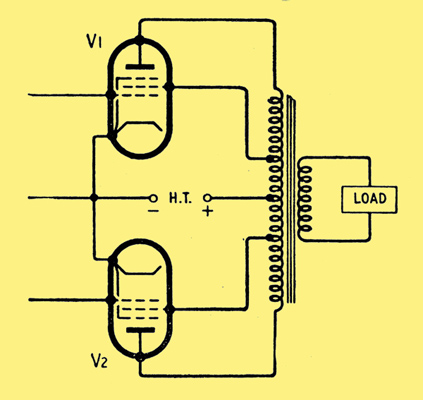
Basic circuit of a push-pull UL output stage.
The diagram above shows a typical basic circuit of a push-pull UL output stage. Unfortunately an equivalent circuit at high frequencies consisting of an array of leakage inductances cannot be drawn for such a circuit. Hence, to show the causes of the above modes of oscillation it is necessary to simplify the circuit. The maximum number of windings which can be dealt with if an equivalent high-frequency circuit is drawn is three, whereas in the above circuit there are effectively five windings. For a three-winding transformer the equivalent leakage inductance circuit can be drawn as three star-connected leakage inductances as illustrated below.
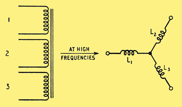
Three-winding transformer and its equivalent circuit at high frequencies. L1, L2 and L3 are leakage inductance components associated with each winding. An 'ideal' transformer should be inserted in two of the limbs to allow for differences in impedance level, but these will be omitted.
To consider the first cause of oscillation the original transformer winding arrangement must therefore be simplified as shown below.
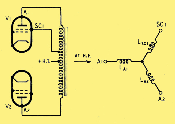
Illustrating the origin of cross-coupling between opposite halves of a push-pull stage.
Now, assuming this simplification is valid, it can be seen that if LA1 >> LA2 then at high frequencies the screen of V1 becomes effectively coupled to A2 and not to A1. If at the same time the screen of V2 becomes effectively coupled to A1, then a cross-coupled system similar to a multivibrator results. Besides this mode of cross-coupling it is also possible for one to be formed by stray capacitances.
Hence for stable operation both of the above faults must be avoided. If a transformer happens to violate the above conditions, matters can often be improved by connecting small capacitors between anodes and their respective screens.
The second cause of oscillation can best be dealt with by consideration of a single-ended output stage.
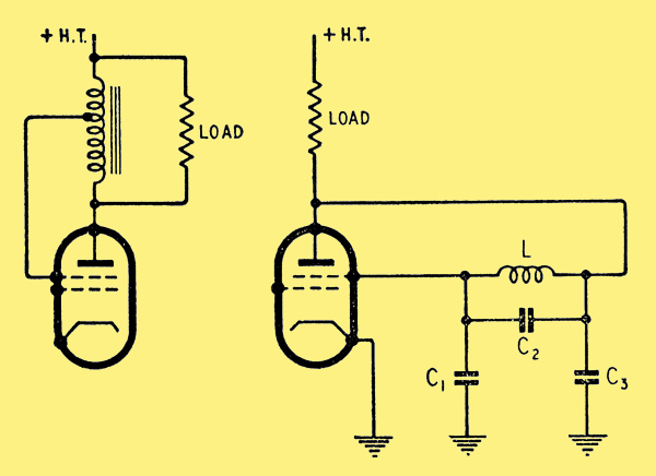
Left: Simple single-ended UL output stage.
Right: Equivalent circuit of the diagram above. L is leakage inductance and C1, C2, C3 are stray capacitances.
The diagram shows the simplest of output stages with a tapped choke and the load connected directly to the anode.
Assuming that the choke can be represented as a two-winding transformer, an equivalent circuit as shown below can be drawn.
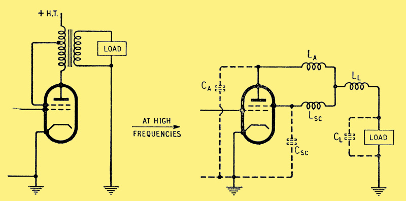
The addition of a secondary winding modifies the conditions shown in the previous two diagrams. LA, LSC and LL are leakage inductances and CA, CSC, CL stray capacitances associated with the three elements of the transformer (and load).
This is the Colpitts oscillator circuit, and if the damping is sufficiently small and the ratio of the stray capacitances correct then oscillation can result. If this trouble occurs it can usually be cured by artificially increasing C2 or better by increasing the damping at high frequencies only, by connecting a series resistor and capacitor combination across C2. The capacitor is necessary to avoid loss of power within the working range.
The inclusion of a secondary winding on the simple tapped choke circuit produces an additional complication. The diagram above illustrates such a circuit with the equivalent high-frequency circuit.
By suitable winding arrangements it is possible to reduce either LA, LSC or LL effectively to zero. The diagram below illustrates this point.
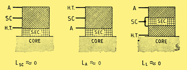
Winding arrangements required to reduce any one of the three principal leakage inductances to a minimum.
The first and second of these possibilities can be used, but in general the third should be avoided unless the load is purely resistive. If the load has a shunt capacitive component then a capacitance exists directly between the junction of LA and LSC and earth. A two-section L-C ladder filter type of network is then produced which causes considerable phase shift with little attenuation, so increasing the possibility of oscillation.
From the foregoing brief discussion the relevant conditions to be observed can be summarized as:
- The inductive coupling between a screen and its associated anode must be kept tighter than with the other anode or the load.
- Stray capacitive coupling between a screen and the opposite anode must be kept small.
- The magnitude of the leakage inductances, anode (1) to screen (1) and anode (2) to screen (2), and the anode and screen capacitances to earth should be kept as low as possible since the higher the frequency at which 'single-sided' oscillations are liable to occur the more easily they will be effectively damped.
To satisfy these requirements there is one main condition to be observed.
- Each half-primary should, if possible, be wound without being sectionalized with the other half- primary or the secondary. If it is necessary to sectionalize each half-primary, then the sections must contain screen and anode subsections in the same proportion as the complete half-primary. Alternatively the sectionalizing can be done by connecting complete half-primary sections in parallel.
To clarify this statement the following case can be considered and is illustrated below. The left hand diagram shows a typical winding arrangement for use with triodes or tetrodes. To convert this to ultra-linear operation the simple arrangement shown on the right should not be used, since it violates the design condition and is liable to be unstable.
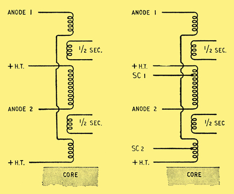
Typical sectionalization of output transformer for normal operation with triodes or tetrodes. If tapped for UL operation in this manner, instability is likely.
Instead the arrangements. shown below can be used, both of which conform to the design condition. The first employs series-connected sections and the latter parallel-connected sections. Unfortunately both are rather complicated and if a very low half-primary to half-primary leakage inductance is not of prime importance, then, by reversing the positions of the primary and secondary windings, a much simpler but nevertheless very satisfactory winding arrangement results.
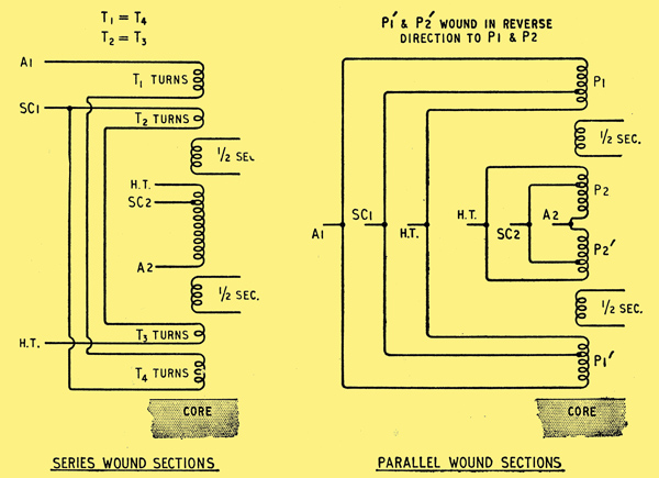
Alternative ideal winding arrangements conforming to the criteria for stable operation in the UL circuit.
The diagram below illustrates this winding arrangement which is suitable for most ultra-linear output stages up to the 30-watt class.
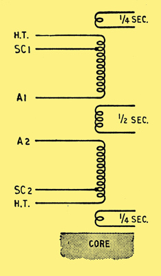
Simplified winding arrangement for UL operation which gives good results in practice.
As a rider to this section it must be said that transformers not designed to the above principles are not necessarily unstable but in general require external stabilization, whereas the above designs in general do not.
Before specifying the design of the output transformer, which as far low and middle frequencies are concerned can be designed along conventional lines, one factor which is often questioned should be explained. It is often asked how such small ultra-linear transformers (e.g., Gilson W0710) can possibly have the low-frequency performance specified. This can be explained as follows. Distortion at low frequencies for a given transformer is approximately proportional to Ra x RL/(Ra + RL) where Ra = effective AC anode resistance and RL = effective load resistance; and hence the lower the effective Ra the lower will be the distortion. Tetrodes have a high effective Ra, and triodes a low effective Ra but also, unfortunately, a low power efficiency. Transformer dimensions increase as the standing anode current increases owing to the greater space required for the primary winding which carries the sum of the standing valve current plus the current due to the power absorbed in the load. Now the ultra-linear circuit combines a low effective Ra with a high efficiency and hence the transformer need not have an excessively large primary inductance and can be wound with relatively thin wire. This produces a transformer whose dimensions are therefore smaller than those of a similar component for either a triode or a tetrode output stage.
An important advantage of this is that in a practical case the leakage inductances can be kept small without complicated sectionalization, such as would be found necessary for a transformer in a triode output stage.
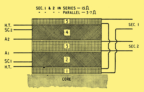
Practical winding sequence equivalent to the simplified circuit above. Details of a transformer for use with N709 valves in UL push-pull are given in tabular form below.
Design for Ultra Linear Output Transformer for N709 Valves in push-pull
Core: 1.25-in stack of No. 29a, 0.014-in thick Stalloy laminations.
Windings (from core) See above diagram. SWG = Standard Wire Gauge
- 45 turns of 22 SWG enamelled copper wire, wound in one layer. 2 turns of 5-mil. Empire cloth.
- 1,940 turns, tapped at 390 turns, of 38 SWG enamelled, 178 turns per layer, 3-mil. paper interleaving each layer. 3 turns of 5-mil. Empire cloth.
- 90 turns of 22 SWG enamelled in two layers. 3 turns of 5-mil. Empire cloth.
- 1,940 turns, tapped at 1,550, 38 SWG enamelled. 178 turns per layer, 3-mil. paper interleaving. 3 turns of 5-mil. Empire cloth.
- 45 turns of 22 SWG in one layer. 1 turn of 5-mil. Empire cloth.
Test Specification
Primary DC resistance 520Ω, anode--to-anode. Secondary DC resistance (on 15Ω) 1.2Ω. Primary inductance at 5Volt, 50Hz = 75H
Leakage inductance, primary-secondary, referred to primary = 28-30 mH
Leakage inductance A1SC1 = 10 mH
Leakage inductance A2-SC2 = 9 mH
Leakage inductance half primary to half primary = 24 mH
See also Ultra Linear Operation, Distributed Loading & Tetrodes with screen feedback
|