|
Further light on the so-called 'Ultra-Linear' circuit
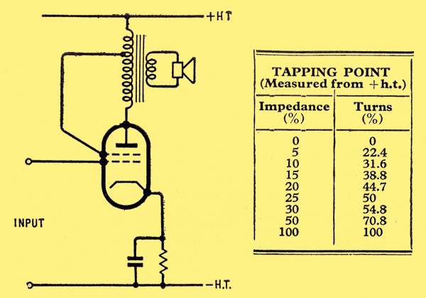
The basic circuit of the UL output valve.
After a period of caution, amounting in some quarters to undisguised scepticism, the 'ultra-linear ' output stage [1] A D Blumlein. British patent No. 496,883 (1937). [2] An Ultra-linear Amplifier, by D Hafler and H I Keroes; Audio Engineering, November 1951. [3] Amplifiers and Superlatives, by D T N Williamson and P I Walker, Wireless World, September 1952. [4] Correspondence: Graham Woodville, Wireless World, November 1954; P I Walker, N F Butler, Wireless World, December 1954. is undoubtedly here to stay. It was unfortunate, though, that Hafler and Keroes in popularizing this circuit for audio amplifiers should have chosen a term which, if it means anything, suggests that the transfer characteristic has been bent 'beyond the straight' and is therefore still curved!
Several alternative descriptions have been suggested, the most plausible being 'triode-tetrode' operation. This hardly does justice to the circuit, since, although at the extreme limits of the screen tapping the valve is undoubtedly operating either as a triode or a tetrode, the intermediate tapping points do not give a progressive transition, so far as distortion is concerned, from one set of characteristics to the other. When the screen tapping point is properly adjusted the transfer characteristic is more nearly linear and distortion is less than that of either the tetrode or the triode connection. Obviously some factor is at work which is not present in either of the limiting conditions and 'triode-tetrode' is misleadingly simple. If it is called the UL circuit the special nature of its performance is underlined, and we do not have to grit our teeth over that 'beyond the linear'.
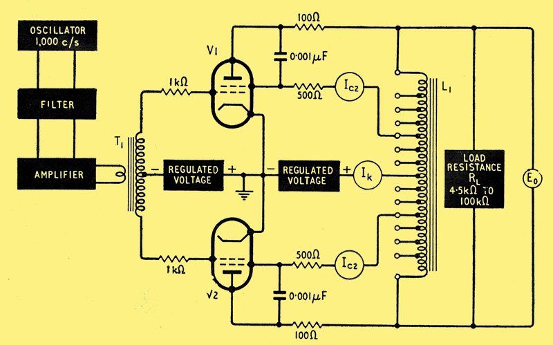
The circuit used by Langford-Smith and Chesterman as a basis for measurements of power output and distortion.
The UL nomenclature is, incidentally, adopted by F Langford-Smith and A R Chesterman who have recently carried out an exhaustive experimental investigation of the push-pull circuit. The results of their measurements with KT66s are given below and it will be noted that they have taken the trouble to adjust the load resistance and bias for the best performance at each tapping point. This ensures that the effects of screen feedback will not be modified or obscured by unfavourable operating conditions.
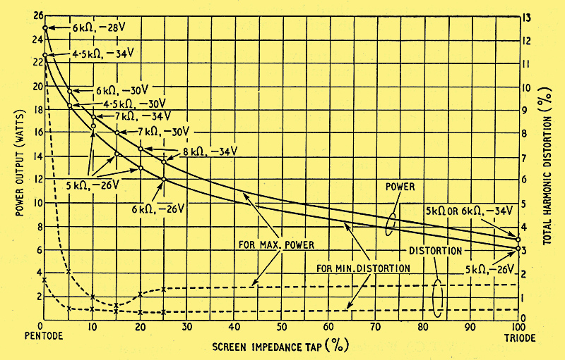
Variation of total harmonic distortion and maximum power (peak input=grid bias) with screen tapping. Load and bias adjusted for optimum performance at each measured point using a pair of KT66 valves with 300V anode and screen supply.
The curve for maximum power shows a clear minimum for a screen tapping of about 15%, and a similar though less pronounced minimum occurs at about 20% under minimum distortion conditions. Both these minima are of lower value than the distortion present under optimum triode conditions.
Any reduction in inherent distortion in the output stage reduces the degree of overall feedback required for a given amplifier performance and so increases the stability margin, but the improvement over triode performance by itself would seldom justify the expense of the extra primary tappings. The real advantage of UL operation is that triode performance in the matter of low inherent distortion is achieved with a power efficiency performance approaching that of a pentode. For a given audio-frequency power output and distortion level, smaller output valves and a less expensive power supply unit can be used with the UL circuit than would be necessary with triodes in the output stage.
For a given anode and screen supply voltage the available power output from a pair of valves in the UL circuit is always less than that given by the same valves operated as pentodes (tetrodes) (see above), and the voltage gain is also less. It is sometimes argued that, provided the amplifier has a stability margin capable of accepting the higher overall feedback necessary to reduce distortion, the same results will be obtained by using normal pentode operation. Langford-Smith points outs that the voltage gain characteristic of a pentode stage (below (a)) is far from linear compared with the UL circuit, and that with pentodes the feed back near full power output will be reduced - just where it is most wanted. It is also stated that since the maximum-signal cathode current is less with UL than with pentode operation and the cathode current efficiencies are approximately the same, it should be possible to increase the anode voltage to bring the UL power output up to the pentode level.

Voltage transfer characteristics of KT66s, (a) as tetrodes, (b) under 20% tap UL conditions. The vertical dotted line indicates the level at which peak input equals the grid bias.
In the test circuit used by Langford-Smith and Chesterman it will be seen that anti-parasitic measures have been liberally applied and the authors mention a tendency towards instability which is attributed to the multiplicity of tappings and their associated switches. This tendency to instability in the UL circuit must not be overlooked. It is closely related to the design of the output transformer and is discussed in detail elsewhere.
Mechanism of the UL Circuit
Although the circuit behaves, so far as reduction of gain and output impedance are concerned, according to the known laws of feedback circuits and shows a smooth transition from the pentode to the triode condition, the conventional feedback formulae fail to account for the dip in the distortion curve at a critical screen tapping point (which varies from valve to valve).
It has been suggested that non-linearity in the screen/anode characteristic may offset curvature of the control grid characteristic, but this cannot be easily checked as the screen characteristics of power output valves are not usually included in the makers literature. But is this basically the right explanation? If the screen curvature is sufficient to cancel the grid curvature at comparatively low levels of feedback (5% in the case of the 6V6) why does it not predominate and cause more than the observed distortion as the screen feedback approaches 100% (triode)?
An alternative and more plausible hypothesis recently published, takes into account the non-linearity resulting from multiplicative mixing when feedback is applied to an electrode other than the input grid. It is known that non-linearity can be introduced into an otherwise linear valve characteristic by applying feedback to the suppressor grid. This form of distortion will be present also when the screen characteristic is itself linear. It is shown mathematically that feedback can be critically adjusted to cancel a particular harmonic (in practice the third) and that as all even harmonics are already cancelled by push-pull operation the residue must consist of higher-order odd harmonics. The analysis has not been extended to these higher harmonics, and although individually they are of amplitudes approaching the experimental threshold of measurement, it is by no means certain that they may not have been increased by the same process which reduced the much stronger third harmonic. In practice, judging from the subjective quality from UL amplifiers we have heard, this effect, if present, is negligibly small; but it would repay investigation (assuming that distortion measurements of sufficient precision are forthcoming) if only to throw more light on the fundamental processes of UL operation.
Acknowledgment
The diagrams other than the first presented are based on Figs. 6, 2 and 5 respectively of Radiotronics (Australia), Vol. 20, No. 5, May, 1955.
References
- A D Blumlein. British patent No. 496,883 (1937).
- An Ultra-linear Amplifier, by D Hafler and H I Keroes; Audio Engineering, November 1951.
- Amplifiers and Superlatives, by D T N Williamson and P I Walker, Wireless World, September 1952.
- Correspondence: Graham Woodville, Wireless World, November 1954; P I Walker, N F Butler, Wireless World, December 1954.
- Ultra linear Amplifiers, by F Langford-Smith and A R Chesterman, Radiotronics, May, June, July, 1955.
- Editorial (WTC), Wireless Engineer, August 1955.
See also Ultra Linear Operation, Distributed Loading & Ultra Linear output transformers
|