|
Amplification Factor and Dynamic Voltage Gain
Previously we discussed the subject of valve characteristics and constants. We considered two of the three important valve constants, these being mutual conductance and anode AC resistance. These constants were considered with respect to the triode valve, it being pointed out that they apply also to amplifying valves having more complicated electrode structures than has the triode.
We shall now proceed to the third important valve constant.
Amplification Factor
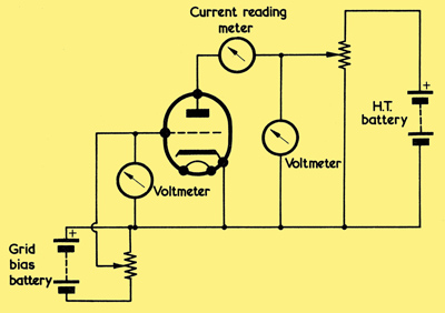
A circuit which allows the characteristics of a triode to be found. Sources of direct voltage other than batteries may, of course, be employed.
As we have already seen, a change in grid voltage, with anode voltage constant, causes a change in anode current. It can also be shown that, if anode current is kept constant, a change in grid voltage causes a change in anode voltage. This fact may be readily observed with the aid of the circuit we used before, and that is repeated above, in which the anode voltage of the valve under consideration can be varied by means of a potentiometer connected across the HT supply, the anode voltage and anode current being indicated by appropriate meters.
If, without any other adjustments, the grid voltage of the valve being investigated is made more negative, anode current will fall. But the anode current can be brought back to its previous value by increasing the anode voltage. Similarly, if grid voltage is made more positive, anode current will increase. Again, the anode current can be returned to its previous value, this time by reducing anode voltage. Thus, in a circuit in which anode current is maintained constant, a change in grid voltage results in a corresponding change in anode voltage.
This relationship is defined by the third important constant of the valve, amplification factor. The amplification factor of a valve is the ratio of change in anode voltage to corresponding change in grid voltage, anode current remaining constant. The two constants previously discussed define ratios between unlike units, and have, themselves, to be expressed in appropriate units. Thus, mutual conductance (the ratio of change in anode current to change in grid voltage) has to be expressed in terms of milliamps per volt. Similarly, anode AC resistance (the ratio of change in anode voltage to change in anode current) has to be expressed in ohms. However, amplification factor is the ratio of change in one voltage to change in another voltage. Both changes are in the same units, and so amplification factor is expressed as a figure on its own, and without any units.
The abbreviation employed for amplification factor is μ (Greek letter 'mu'), and it may be expressed as:-
μ = δVa/δVg (Ia constant)
The denominator of the fraction (δVg) represents 'change in Vg, and the numerator (δVa) represents 'corresponding change in Va'. It will be noted that this fraction has the same form as those we saw in the last article for mutual conductance and anode AC resistance.
As is to be anticipated, the amplification factor of a triode under normal conditions is always greater than 1. Typical figures for triodes en-countered in practice range from around 10 to 100.
Occasionally, a triode may be classified as a 'low-mu' type or a 'high-mu' type to give an indication of the performance which may be expected of it. As an example, the double-triode type 12AU7 consists of two similar triodes in a single envelope and these, with an amplification factor of 19 at an anode voltage of 100, are sometimes referred to as 'low-mu' triodes. Another double-triode, the 12AX7, also has two similar triodes in a single envelope, these having an amplification factor of 100 at an anode voltage of 100. The 12AX7 triodes are, in consequence, sometimes referred to as 'high-mu' triodes. Occasionally, the term 'medium-mu' may also be met. These three terms are approximate only, and should be looked upon as offering only a rough idea of the capabilities of a triode.
When we discussed mutual conductance and anode AC resistance, we also examined the characteristic curves which correspond to these quantities. With mutual conductance we had IaVg curves with anode voltage as parameter, and with anode AC resistance we had IaVa curves with grid voltage as parameter. There is no reason why, with amplification factor, we could not similarly have a set of IaVg curves with anode current as parameter but, in practice, such curves are very rarely drawn or encountered. This is because adequate information on valve performance may be obtained from the IaVg and IaVa curves. Also, these provide the most convenient means of obtaining any further information which may be required on the valve.
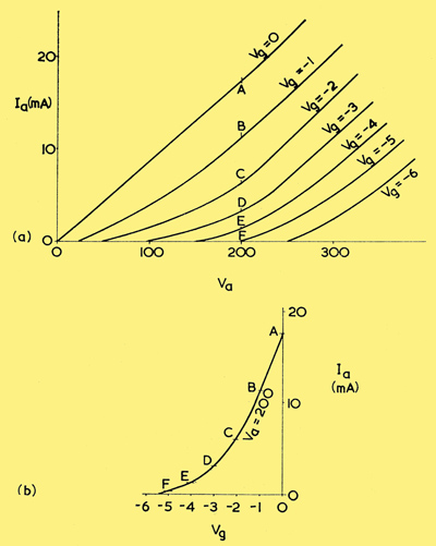
(a) A set of IaVa curves for a typical triode
(b) The information in the curves may be employed to draw a set of IaVa curves. In this diagram an IaVg curve for Va = 200 is shown, the plotting points (A to F) being taken from the IaVa curves in (a).
It is interesting to note that it is possible to draw any of the three sets of curves from the information offered by one set only, provided that sufficient parameter values are given. The graphs included above show, for instance, a family of IaVa curves with grid voltage as parameter. These can be used to plot a set of IaVg curves with anode voltage as parameter. (a) tells us that, at a Va of 200, a Vg of zero corresponds to an Ia of 17 mA, a Vg of -1 corresponds to an Ia of 11 mA, a Vg of -2 to an Ia of 6 mA, a Vg of -3 to an Ia of 3 mA and so on. These are the points where the appropriate Vg curves pass the 200 Volt Vg co-ordinate, and are indicated in (a) by the letters A to F. If these points are plotted on an IaVg graph we may then draw an IaVg curve corresponding to a Vg of 200. Such a curve is shown in (b). IaVg curves corresponding to other values of Vg may similarly be drawn. The process is laborious, yet it emphasises that IaVa and IaVg curves present the same basic information, but on different axes. Readers who have access to manufacturers valve data may find it of interest to check the points of correlation between IaVa and IaVg curves when both sets of curves are given for a specific valve.
A set of VaVg curves could also be obtained by the same process. In this instance Ia would be the parameter. The values of Va for different values of Vg at any fixed Ia may be obtained from the IaVg or the IgVg curves, and a new set of VaVg curves drawn up.
Relationship Between Constants
We have now found that, for mutual conductance,
gm = δIa/δVg (Va constant)
for anode AC resistance,
ra = δVa/δIa (Vg constant)
and for amplification factor,
μ = δVa/δVg (Ia constant).
It is possible from these equations, to find a relationship between gm, ra and μ. A simple approach consists of first multiplying gm and ra, a process which gives us:-
δIa/δVg x δVa/δIa
The two δIa terms cancel out, and the expression then becomes
δVa/δVg,
which is that for μ.
Thus, μ = gm ra
Similar multiplications can also show that:-
gm = μ/ra
and that
ra = μ/gm
It should be added that these three relationships are only completely accurate when μ, gm and ra are evaluated for changes around the same anode voltage, anode current and grid voltage. The definition of μ assumes Ia is constant. When above we cancelled out the two δIa terms the definition for μ holds good when δIa is almost infinitesimally small and so the relationship is accurate.
It should be added that these three relationships are only completely accurate when μ, gm and ra are evaluated for changes around the same anode voltage, anode current and grid voltage.
Dynamic Conditions
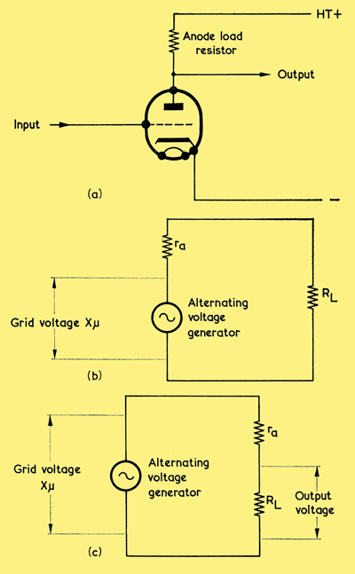
(a) if a valve is to function as an amplifier it requires an anode load across which the output voltage may appear. (Bias components are omitted here for simplicity)
(b) The valve may be replaced by an alternating voltage generator in series with the ra of the valve, as shown here
(c) Moving ra to the right demonstrates that the output voltage is that dropped across RL in the potentiometer RL + ra.
The three valve constants we have discussed do not enable us to directly evaluate performance in a practical valve amplifier circuit. We could, for instance, try to determine the performance of a valve amplifier by using the mutual conductance figure. But if we are to use a valve as a practical amplifier we have to provide it with an anode load, such as is given by the anode load resistor for the triode in (a) above. The sole function of the anode load is to provide a large varying voltage on the anode. If we want to determine the performance of the valve in this circuit, what use is the mutual conductance figure which is dependent upon a fixed anode voltage?
Fortunately, a valves performance under working, or dynamic, conditions may be readily found from its constants, all that is required being one or more simple arithmetical or graphical steps which allow the valves load to be taken into account.
As a start, let us find the voltage amplification, or voltage gain, offered by the triode of (a). This voltage amplification will be given by the alternating voltage across the anode load resistor RL divided by the alternating voltage applied to the grid. (In choosing the symbol RL for the anode resistor we are working to the generally accepted convention concerning valve quantities. If any quantity is inside a valve it is represented by a small letter, and if it is outside the valve it is represented by a capital letter. The anode load of the triode of (a) is a resistance outside the triode and we refer to it as RL, with a capital R. Shortly, we shall be introducing the anode AC resistance which, as we already know, is referred to as ra. A small letter r is used here because the anode AC resistance is inside the valve.)
Our first step consists of replacing the valve by an equivalent alternating voltage generator offering the same alternating voltage as is given at the anode of the valve. This alternating voltage will be equal to the alternating voltage at the grid multiplied by the valves amplification factor, μ. We saw in the last article that the anode AC resistance of the valve, ra, can be looked upon in the same manner as the internal resistance of a generator. This resistance must, therefore, be added in series with the generator if our new circuit is to be exactly equivalent to that given with the valve. The result is shown in (b), in which diagram the valve is replaced by the AC generator in series with ra, the combination being then applied to the anode load resistor RL. We next move ra over to the right hand side of the diagram, as in (c), since this new position helps to demonstrate that ra and RL form a potentiometer. The output alternating voltage across RL is then RL/(RL + ra) of the alternating voltage given by the generator. Since the latter is the grid alternating voltage multiplied by μ, it follows that:-
Alternating Voltage across RL = (RL/(RL + ra)) x μ x Alternating Voltage at grid.
This formula is commonly used to evaluate voltage amplification in a circuit of the type shown in (a), and it enables the modifying effect of the load resistor to be taken into account. It should be pointed out that it is only completely accurate in the cases where the valve is worked over the linear (i.e. straight line) parts of its characteristics because otherwise, μ and ra may vary.
In practice, the accuracy of results obtained with this formula will be more than adequate enough for most audio work, and particularly when small alternating voltages (which are less likely to run the valve over excessively non-linear sections of its characteristics) are concerned.
In some circuits, a very low anode resistance (or impedance) is employed. If this resistance (or impedance) is considerably lower than the anode AC resistance of the valve it can be ignored in the denominator (lower part) of the fraction, because it is much lower than the ra to which it is added. Voltage amplification then becomes approximately equal to:-
μRL/ra.
We saw, earlier on in this article, that mutual conductance is equal to μ/ra, so we may then say that voltage amplification under these conditions is approximately equal to gm.RL. It must be emphasised that this approximate relationship is only true when RL is considerably lower than ra.
|