|
The Cooper-Smith 20 Watt Amplifier provides a true high fidelity output at high power. It is an instrument which is ideal for high grade sound reinforcement and public address- systems, and it can also fulfil applications in the domestic field.
Domestically, the amplifier would normally be operated below its rated output, the fact that it has a considerable degree of undistorted power in reserve ensuring that transients and the like are reproduced truthfully without approaching overload at any time
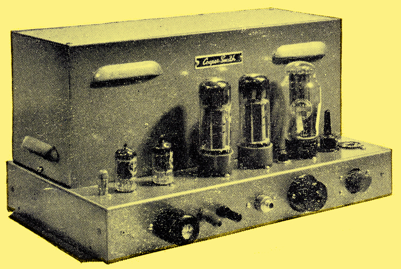
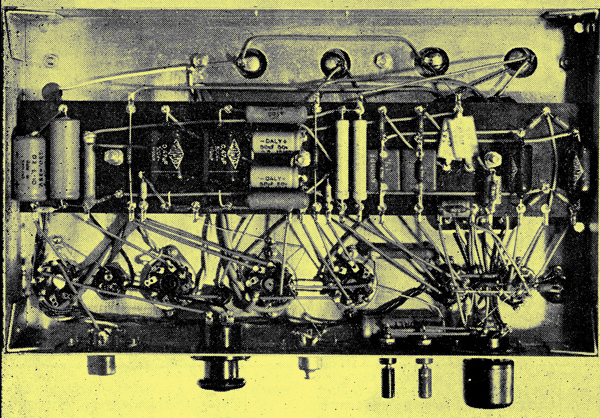
The photograph at the head of this article clearly illustrates the clean and well planned layout of the amplifier. An under-chassis illustration is also shown, and it will be seen from this that component layout has the same neatness, and exhibits the same care in design, as has been evident in previous equipments in the Cooper-Smith series.
Amplifier Features
The amplifier is designed to operate in conjunction with the Cooper-Smith Mk. II Control Unit, although other pre-amplifiers could be used instead if they meet input requirements. Power supply sockets are available both for the pre-amplifier and for a radio tuner unit. There is also an outlet which may be used for supplying mains voltage to a gram motor or to any similar ancillary equipment. On-off switching for the power amplifier is achieved at the Control Unit, and the pre-amplifier socket carries the necessary wiring for this facility.
A special feature of the amplifier is given by the output transformer. This component is of heavy construction and employs C-cores instead of normal laminations to keep leakage inductances to a minimum. The transformer is coupled to the output valves in an ultra-linear circuit. Output impedances at 3.8, 8.5 and 15.2 Ohms are available, these being selected by fitting individual plugs into a special 9-way matching socket. The plugs are identified by the output impedance they provide and they are wired internally such that appropriate combinations of the output transformer secondary windings are presented to the two loudspeaker terminals. The plugs also carry components which enter the negative feedback loop, these components ensuring that feedback at the correct level is achieved whatever output impedance is selected.
Especial attention has been paid in the design of the amplifier to the prevention of hum. A centre-tapped 6.3 volt secondary on the mains transformer supplies the heaters of the first two valves in the amplifier circuit, and is available for use by the pre-amplifier and radio. tuner unit as well. Main HT smoothing is carried out with paper, and not electrolytic, capacitors. Fuses are provided both in the mains input and in the HT supply circuit.
The technical specification for the amplifier is as follows:
- Output: 20 Watts nominal, 30 Watts maximum.
- Distortion: 0.1% at full output.
- Input Sensitivity: 650 mV referred to 29.3 Watts.
- Frequency Response: 30-30,000 Hz ±0.5 dB.
- Feedback: 26dB.
- Noise Level: -80dB referred to 29.3 Watts.
- Output Impedance: 3.8, 8.5 or 15.2 Ohms
- Output: EL34s, ultra-linear.
- Size: 14 x 8.25 7.75 inches.
- Weight: 26lb.
The Amplifier Circuit
Circuit diagram
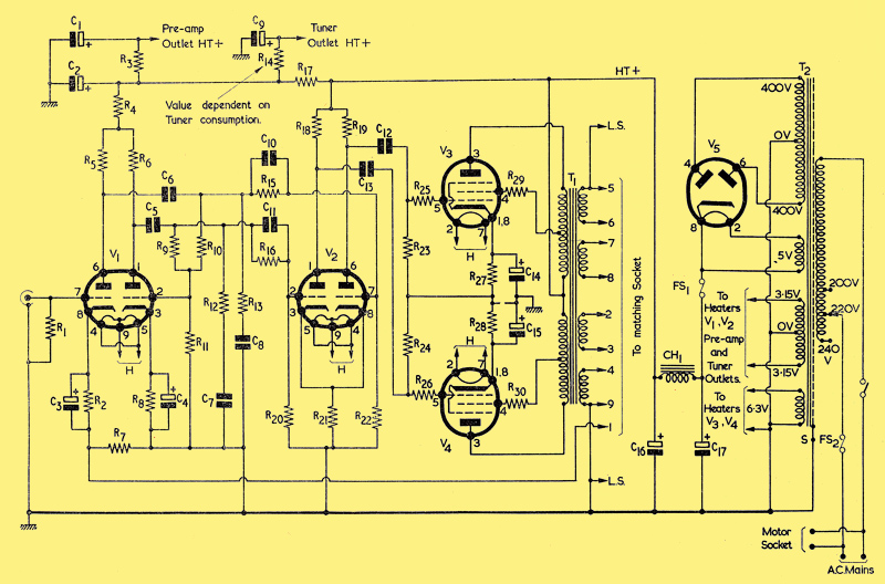
The circuit of the amplifier is shown above. In this diagram the input signal is applied to the left hand triode of V1 (12AX7). The two triodes of V1 are employed in a 'floating paraphase' circuit, AF voltages of opposite phase appearing at the anodes. In the 'floating paraphase' circuit the grid of the right hand triode of V1 taps into the junction of R9 and R19. The value of R9 is slightly greater than R10, with the result that the grid receives a small proportion of the AF voltage on the anode of the left hand triode, the necessary phase reversal then taking place in the right hand triode itself. The circuit is self balancing, with the consequence that the AF voltages on the anodes are of equal amplitude.
The AF on the anodes of V1 are fed, by way of the frequency correcting components R12, R13, R15, R16, and C7, C8, C10, C11, to the grids of V2 (12AU7). The triodes of V2 amplify the AF voltages independently, but they share a common un-bypassed cathode bias resistor in order to reduce the effects of any unbalance in the applied signals, or in the triodes themselves.
The two outputs from V2 are fed, via C12 and C13 and the stoppers R25 and R26, to the grids of the output pentodes V3 and V4. These two valves are EL34s and they function in an ultra-linear circuit, their screen-grids being returned to taps in the primary winding of the output transformer. The secondary windings of the output transformer connect to the 9-way matching socket, the required output impedance being selected by choice of the appropriate plug. Each of the output impedance matching plugs contains a resistor and parallel capacitor which couples pin 5 of the matching socket to pin 1. As will be shown shortly (when the matching circuit is considered in greater detail) the matching plug then allows a negative feedback voltage to be applied from the output transformer secondary to the cathode circuit of the left hand triode of V1.
In the power supply section the mains input is applied to the Motor Socket and, via fuse FS2 and the on-off switch, to the primary of the mains transformer. The Motor Socket is permanently connected to the mains supply and is not controlled by the amplifier on-off switch. This is to allow the motor to be switched off independently by its own control or mechanism, thereby obviating the possibility of the formation of 'flats' on its drive wheel. The on-off switch shown is, in practice, intended to be mounted in the pre-amplifier (a suitable switch is already available in the Cooper-Smith Mk. II Control Unit) and the appropriate wiring is, in consequence, coupled to the pre-amplifier socket on the power amplifier chassis. Fuse FS2 is incorporated in the bridging link of the mains voltage selection panel.
The 400-0-400 Volt secondary of the mains transformer connects to the rectifier V5. This is a GZ32 and the rectified voltage on its cathode is applied, via fuse FS1, to the smoothing circuit given by paper capacitors C16 and C17, and the heavy duty smoothing choke CH1. The smoothed voltage is supplied direct to the anode and screen-grid circuits of V2, V3 and V4, and it is decoupled, by R17 and C2, for the anode circuits of V1. This decoupled supply is further filtered, by R3, C1, and R14, C9, for use by the pre-amplifier and tuner units respectively.
The Loudspeaker Matching Circuit
As was pointed out earlier, the three output impedances available from the amplifier are obtained by fitting appropriate plugs into the 9-way impedance matching socket. The manner in which these plugs select the desired impedance is illustrated below.

The different ways in which the output transformer secondary windings are interconnected by the matching plugs. The 15.2 Ohm matching circuit is shown in (a), the 8.5 Ohm circuit in (b), and the 3.8 Ohm circuit in (c).
(a) shows the internal wiring of the 15.2 Ohm plug, together with the resultant output transformer secondary connections. As may be seen, the plug causes all four secondary windings to be connected in series. (b) gives the internal wiring and the resultant secondary connections effected by the 8.5 Ohm plug. In this instance the two centre windings are connected in parallel, this parallel combination being in series with the two outside windings. In (c) the 3.8 Ohm plug, and the consequent secondary winding connections, are shown. This time the top and third windings are connected in series, as are the second and fourth windings. These two series combinations are then paralleled for application to the loudspeaker terminals. The diagram clearly illustrates the fact that the different output impedances are obtained with optimum utilisation of the four secondary windings.
The negative feedback circuit is completed, in each plug, by the parallel resistor and capacitor connected between pins 5 and 1. For 15.2 Ohm operation these have values of 470 Ohm and 300 pF, for 8.5 Ohm operation values of 300 Ohm and 470 pF, and for 3.8 Ohm operation values of 240 Ohm and 600 pF. Thus, the plugs automatically ensure that correct feedback is achieved, despite the varying AF voltages appearing at the loudspeaker terminals for different impedance connections.
If the amplifier is obtained in kit form, a 15.2 Ohm plug is normally supplied unless alternative impedances are specified.
Pre-amplifier and Tuner Connections
The connections to the pre-amplifier and tuner unit sockets are illustrated below.
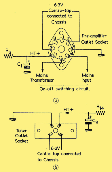
The connections to (a), the pre-amplifier socket and (b) the tuner unit outlet socket. In both cases, the diagram gives a rear view of the socket.
(a) shows the International Octal 8-way pre-amplifier socket connections. Pins 2 and 7 carry the 6.3 volt heater supply, pin 3 provides the chassis connection and pin 6 the HT positive supply, via R3. Pin 4 connects to the mains input and pin 5 to the mains transformer. Pins 4 and 5 have, therefore, to be bridged for the mains input to be applied to the power supply transformer. Such, bridging is effected by the on-off switch in the pre-amplifier specified for use with the amplifier.
It should be pointed out that Cooper-Smith Mk. II Control Units may have AF output plugs different from the type required for the present amplifier. If this is the case, such plugs may be easily replaced by the type needed here; and a suitable plug is specified in the components list.
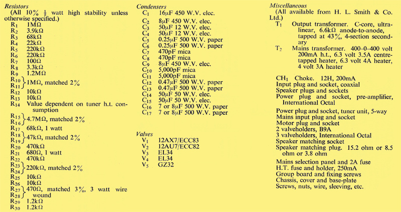
Components list
A 5-way socket is employed for the tuner unit, and this is wired as shown in (b). The services provided here are an HT positive supply via R14, chassis, and a 6.3 V heater supply
The heater current available for both pre-amplifier and radio tuner unit is 2.9 A. The heater consumption of the Mk. II Control Unit is 0.5 A, with the result that, if this pre-amplifier is employed, 2.4 A is available for the tuner unit. It is important to note that the heater supply for both tuner unit and pre- amplifier is taken from a heater winding whose centre-tap is connected to the power amplifier chassis. If the pre-amplifier or tuner unit has one side of its heater supply connected to chassis, such a connection must be broken before coupling to the power amplifier, or damage to the mains transformer or wiring will result.
The HT current available for both pre-amplifier and tuner unit is of the order of 40 mA. A value for the series resistor, R14, is not specified, as this will vary according to the current and voltage requirements of the tuner unit.
Under chassis view
Construction
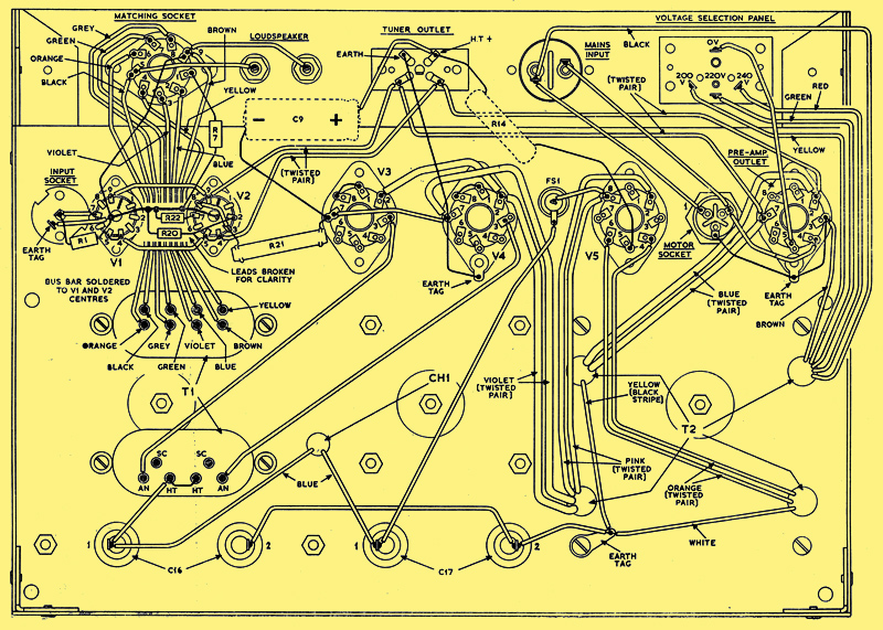
The layout of the components and wiring fitted in the first wiring stage.
The construction of the Cooper-Smith 20 Watt amplifier is fully described in the step-by-step instructions which follow. These instructions may be followed with the aid of the wiring diagrams. In both these diagrams the front apron of the chassis is shown laid flat in order that connections to the sockets and panels mounted on it may be indicated more clearly.
Mounting the main components.
- Fit the three long 2BA bolts (supplied) to the chassis (heads above chassis). Make certain that the bolts are securely tightened, as the heads and nuts are covered in later stages of assembly. The bolts take up the positions circled in the diagram above.
- Fit the voltage selection panel, tuner outlet panel and matching socket to the front chassis apron. All these are fitted from the inside of the chassis. Fit the mains input socket, from the outside. Fit the loudspeaker sockets with a Paxolin washer on each side, taking care not to over-tighten the nuts.
- Fit the valve-holders and pre-amplifier outlet socket to the chassis, from the inside, ensuring correct orientation and fitting chassis solder tags as shown. Ensure that good contact is made to chassis by the tags by scraping, or cleaning, the chassis immediately underneath the appropriate valve-holder or socket metalwork. Next fit the input socket, ensuring correct orientation, as shown, and scraping the chassis to provide good connection. Fit fuse-holder FS1 and the motor socket. The long pin on the latter is towards the centre of the chassis.
- Mount output transformer T1, mains transformer T2, and the smoothing choke CH1, ensuring correct orientation. Whilst mounting, pass the coloured lead-out wires of the mains transformer, T2, through the holes indicated. Similarly pass the two blue leads of the smoothing choke through the chassis hole indicated. A solder tag is fitted under one securing bolt of T2 and the chassis underneath must be scraped to ensure good contact.
- Fit the smoothing capacitors C16 and C17. These may be fitted either way round as they are not electrolytic components. Whilst clamping down ensure that the tag which takes up position 1 in each case is well clear of chassis.
- Fit the cover over the transformers, choke and capacitors just mounted. This will enable the chassis to stand upside-down squarely whilst wiring proceeds.
Wiring-up - First Stage
Wiring up now commences. In order that all connections may be made to each individual tag before they are soldered to that tag, soldering should only be carried out resistors referred to are 0.5 Watt 10%, and all connecting wires are covered with sleeving. Resistor and capacitor lead-out wires are not sleeved unless otherwise stated.
- Connect together, without sleeving, pins 4 and 5 of V1. Similarly connect together pins 4 and 5 of V2. Using twisted wiring and sleeving, connect together pin 9 of V1, pin 9 of V2, the lower left hand tag of the tuner outlet panel and pin 7 of the pre-amplifier outlet socket; connect together pin 4 of V1 and pin 5 of V2; connect together pin 4 of V2, the lower right hand tag of the tuner outlet panel and pin 2 of the pre-amplifier outlet socket. In common with other heater leads, the pairs of wires between the points just connected are shown as separate leads in the diagram above for reasons of clarity; in practice they should be twisted, including the pair between V1 and V2. Solder all the connections just made except for those at pins 2 and 7 of the pre-amplifier outlet socket.
- Connect the two blue lead-out wires from mains transformer T2 to pins 2 and 7 of the pre-amplifier outlet socket, twisting these two wires before connecting. Solder at pins 2 and 7.
- Connect, and twist, the two orange leads from T2 to pins 4 and 6 of V5, soldering at these pins.
- Connect, and twist, the two pink leads from T2 to pins 2 and 8 of V5, soldering at pin 2 only.
- Connect, and twist, the two violet leads from T2 to pins 2 and 7 of V4.
- Connect pin 2 of V3 to pin 2 of V4. Connect pin 7 of V3 to pin 7 of V4. Solder at pin 2 of V3 and pin 2 of V4.
- Connect the yellow (black stripe) and white leads from T2 to the chassis tag as indicated.
- Connect the brown lead from T2 to pin 3 of the pre-amplifier outlet socket. Without sleeving, connect pin 3 of the pre-amplifier outlet socket to the adjacent chassis tag. Solder at pin 3.
- Connect the black lead from T2 to the left hand tag of the mains input socket. Connect the left hand tag of the mains input socket to tag 1 of the motor socket. Solder all connections.
- Connect the red lead from T2 to the 240 V tag on the voltage selection panel. Connect the green lead from T2 to the 220 V tag on the voltage selection panel. Connect the yellow lead from T2 to the 200 V tag on the voltage selection panel. Solder all connections.
- Connect one blue wire from smoothing choke CH1 to tag 1 of C16, and the other blue wire to tag 1 of C17.
- Connect tag 2 of C16 to tag 2 of C17, and tag 2 of C17 to the adjacent chassis tag. Solder all connections except tag 2 of C16.
- Identify the HT tags on output transformer T1. Some transformers have only one HT tag. If the transformer employed has two tags connect these together without sleeving. Connect the HT tags (or tag) to tag 1 of C16, using sleeving. Solder all connections, except tag 1 of C16.
- Connect together tag 1 of C17 and the outer tag of fuse-holder FS1. Solder both connections.
- Connect the 0 V tag on the voltage selection panel to pin 5 of the pre-amplifier outlet socket. Solder both connections.
- Connect the right hand tag of the mains input socket to the upper right hand tag of the motor socket, continuing to pin 4 of the pre-amplifier outlet socket. Solder all connections.
- Connect the lower (earth) tag of the motor socket to the adjacent chassis tag as indicated. Solder both connections.
- Connect the 'centre' tag ) of fuse-holder FS1 to pin 8 of V5. Solder both connections.
- Using un-sleeved wire connect pin 7 of V4 to the upper left hand tag of the tuner outlet panel and to the adjacent chassis tag, as indicated. Solder all connections.
- Using un-sleeved wire connect together pins 1 and 8 of V3. Similarly connect together pins 1 and 8 of V4. Solder at pin 8 of V3 and pin 1 of V4.
- Reverting to sleeved wire, connect pin 3 of V4 to the right hand AN tag of T1. Connect pin 3 of V3 to the left hand AN tag of T1. Solder all connections.
- Connect the coloured leads from output transformer T1 to the matching socket tags in the following manner. Blue lead to tag 2, violet lead to tag 3, yellow lead to tag 4, black lead to tag 5, orange lead to tag 6, green lead to tag 7, grey lead to tag 8, brown lead to tag 9. All these leads travel between V1 and V2 valve-holders and should be kept close to the chassis. They may pass under the twisted heater pair between these two valve-holders. This twisted pair should also be pressed down towards the chassis after the output transformer wires have been fitted. Solder all connections just made except for those at tags 5 and 9.
- Connect tag 5 of the matching socket to the left hand loudspeaker terminal. Connect tag 9 of the matching socket to the right hand loudspeaker terminal. Solder all connections except that at tag 9.
- With stout, un-sleeved, tinned copper wire, form a bus-bar between the centre spigots of V1 and V2 valve-holders in the manner shown below. Clench the wire securely to the centre spigots and solder at the V2 spigot only.
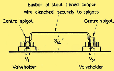
Side view, showing how the busbar is fitted between the centre spigots of V1 and V2.
- With sleeved wire join pins 3 and 8 of V1. Solder at pin 8.
- Without sleeving, connect tag 9 of the matching socket to V1 spigot. Solder at tag 9.
- Using sleeving, connect the earthy, outer, tag of the input socket to V1 spigot, or to the bus-bar wire adjacent to the spigot, if the latter is crowded. Solder at the earth tag.
- Connect the centre tag of the input socket to pin 7 of V1. Connect R1 (1MΩ) between the centre tag of the input socket and V1 spigot, or to the bus-bar wire adjacent to the spigot, if the latter is crowded. Solder at pin 7 of V1 and at the centre tag, and solder all connections, including the bus-bar, at V1 spigot.
- Connect R7 (100&Omega]) between tag 1 of the matching socket and the bus-bar. Solder at the bus-bar.
- Connect R22 (470kΩ) between pin 7 of V2 and the bus-bar. Solder at the bus-bar.
- Connect R20 (470kΩ) between pin 2 of V2 and the bus-bar. Solder at the bus-bar.
- Connect R21 (680Ω, 1 W) between pin 3 of V2 and pin 7 of V3. Solder at pin 3.
- If a tuner unit HT outlet is required, connect C9 (8μF, 450 V) between pin 7 of V3 and the upper right hand tag of the tuner outlet panel. Ensure correct polarity in C9 and sleeve its positive lead-out wire. Also connect R14 (value according to tuner unit HT requirements) between the upper right hand tag of the tuner outlet panel and pin 5 of V5. Solder at the tuner outlet panel tag. Whether C9 and R14 are fitted or not, solder also at pin 7 of V3.
The first stage of the wiring is now complete.
Wiring-up - Second Stage
The second stage of wiring is concerned with the fitting of components to the group board, and should be carried out before the board is fitted to the chassis. The connections made are shown below, which illustrates both the second and third wiring stages. When it is wired, the group board will be mounted over the three long 2BA bolts fitted in step 1. Sufficient clearance should be left between components and wiring adjacent to the three corresponding holes in the group board to enable the securing 2BA nuts and washers to be eventually fitted and tightened up.
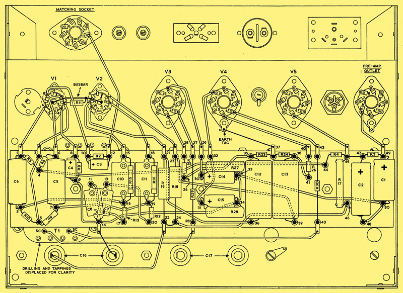
The components and wiring fitted in the second wiring stage.
All the connections made in the second wiring stage are to the holes in the appropriate tags and eyelets. It is only in the third stage that connections are made to the tags projecting over the sides of the group board. The tags and eyelets on the group board are numbered in the diagram above. The instructions which follow refer to these numbers, and, also, to the eyelets as 'tags'. There is no wiring under the group board.
- Using sleeving, connect together the following tags, ensuring that no wire passes over other tag holes where they might hinder later soldering operations. 4 and 44; 3 and 5; 2 and 16; 7 and 19; 9, 14, 34, 33, 50 and 48; 11 and 17; 13 and 20; 21 and 36; 23 and 39; 26 and 35; 29 and 30; 31 and 32; 38 and 41. Omitting sleeving between 22 and 24, connect together 22, 24 and 46. Without sleeving connect together 45 and 47.
- Connect C6 (0.25μF, 500 V) between tags 1 and 2.
- Connect R5 (220kΩ) between tags 1 and 4, soldering at 1.
- Connect R6 (220kΩ) between tags 4 and 6, soldering at 4.
- Connect R10 (1MΩ, matched 2%) between tags 2 and 5, soldering at 2.
- Connect R9 (1.2MΩ) between tags 5 and 7, soldering at 5.
- Connect C5 (0.25μF, 500 V) between tags 6 and 7, soldering at both tags.
- Connect, in parallel, C4 (50μF, 12 V) and R8 (3.3kΩ) between tags 8 and 9, observing correct polarity on C4. Solder at both tags.
- Connect, in parallel, C3 (50μF, 12 V) and R2 (3.9kΩ) between tags 10 and 12, observing correct polarity in C3. Solder at both tags.
- Connect C7 (470pF) between tags 13 and 14, soldering at 13.
- Connect C8 (470pF) between tags 11 and 14, soldering at both tags. As shown, C8 is positioned so that it overlaps C7.
- Connect, in parallel, C10 (5,000pF) and R15 (4.7MΩ, matched 2%) between tags 15 and 16, soldering at tag 15.
- Connect, in parallel, C11 (5,000pF) and R16 (4.7MΩ, matched 2%) between tags 18 and 19, soldering at 18.
- Connect R13 (10kΩ) between tags 16 and 17, soldering at both tags.
- Connect R12 (10kΩ) between tags 19 and 20, soldering at both tags.
- Connect R19 (47kΩ, matched 2%) between tags 21 and 22, soldering at both tags.
- Connect R18 (47kΩ, matched 2%) between tags 23 and 24, soldering at both tags.
- Connect R25 (10kΩ) between tags 25 and 26, soldering at both tags.
- Connect R29 (1.2kΩ) between tags 27 and 28, soldering at both tags.
- Connect, in parallel, C14 (50μF, 50 V) and R27 (470Ω 3 W, matched 3%) between tags 30 and 33, observing correct polarity in C14. Solder at both tags. R27 dissipates heat and must be kept clear of adjacent components.
- Connect, in parallel, C15 (50μF, 50 V) and R28 (470Ω, 3 W, matched 3%) between tags 31 and 34, observing correct polarity in C15. Solder at both tags. R28 dissipates heat and must be kept clear of other components.
- Connect C12 (0.47μF, 500 V) between tags 35 and 36, soldering at 36.
- Connect C13 (0.47μF, 500 V) between tags 38 and 39, soldering at 39.
- Connect R23 (220kΩ, matched 2%) between tags 35 and 37, soldering at 35.
- Connect R24 (220kΩ, matched 2%) between tags 37 and 38, soldering at both tags.
- Connect R26 (10kΩ) between tags 40 and 41, soldering at both tags.
- Connect R30 (1.2kΩ) between tags 42 and 43, soldering at both tags.
- Connect R4 (22kΩ) between tags 44 and 45, soldering at 44.
- Connect R17 (68kΩ, 1 W) between tags 45 and 46, soldering at both tags.
- Connect C2 (8μF, 450 V) between tags 47 and 48, observing correct polarity. Solder at 48.
- Connect C1 (16μF, 450 V) between tags 49 and 50, observing correct polarity. Solder at 50.
- Connect R3 (68kΩ) between tags 47 and 49, soldering at both tags.
The second stage of wiring is now complete.
Wiring-up - Third Stage
In this stage all connections made to group board tags are soldered to the tag projections on either side of the board. The third wiring stage is also illustrated in the wiring diagram above.
- Solder two un-sleeved wires, each 9 in long, to the SC tags on output transformer T1.
- Fit R11 (1MΩ, matched 2%) between pin 2 of V1 and the bus-bar, soldering at the bus-bar.
- Mount the group board over the three long 2 BA bolts, employing nuts and washers above and below. Adjust the nuts such that the group board is approximately 0.75 in above the chassis and tighten the mounting nuts. Temporarily pass the two 9 in leads just soldered to the SC tags of T1 over the rear apron of the chassis, so that they are out of the way until required.
- Connect tag 1 of the group board to pin 6 of V1, soldering both connections.
- Connect tag 3 to pin 2 of V1, soldering both connections.
- Connect tag 6 to pin 1 of V1, soldering both connections.
- Connect tag 8 to pin 3 of V1, soldering both connections.
- Connect tag 10 to pin 8 of V1, soldering both connections.
- Connect tag 12 to tag 1 of the matching socket, soldering both connections.
- Connect tag 15 to pin 7 of V2, soldering both connections.
- Connect tag 18 to pin 2 of V2, soldering both connections.
- Connect tag 21 to pin 6 of V2, soldering both connections.
- Connect tag 23 to pin 1 of V2, soldering both connections.
- Connect tag 25 to pin 5 of V3, soldering both connections.
- Connect tag 27 to pin 4 of V3, soldering both connections.
- Connect tag 29 to pin 1 of V3, soldering both connections.
- Connect tag 32 to pin 8 of V4, soldering both connections.
- Without sleeving, connect tag 37 to V4 chassis tag, as indicated.
- Connect tag 40 to pin 5 of V4, soldering both connections.
- Connect tag 42 to pin 4 of V4, soldering both connections.
- Connect tag 45 to pin 5 of V5, soldering both connections.
- Connect tag 49 to pin 6 of the preamplifier outlet socket, soldering both connections.
- Fitting sleeving, and shortening the previously-fitted lead as necessary, connect the right hand SC tag of T1 to tag 43, soldering at tag 43.
- Fitting sleeving, and shortening the previously-fitted lead as necessary, connect the left hand SC tag of T1 to tag 28, soldering at tag 28.
- Connect tag 22 to tag 1 of C16. Solder both connections.
- Without sleeving, connect tag 14 to tag 2 of C16. Solder both connections.
Wiring up is now complete.
Amplifier Operation
The base-plate should next be fitted to the amplifier, this being secured by the long 2 BA screws with nuts and washers on either side. The base-plate provides added strength for the amplifier chassis and helps to carry the weight of the chokes and transformers. It prevents any buckling of the chassis should the latter be accidentally dropped.
The mains voltage selection panel should be set to the correct tapping, bearing in mind the fact that the bridging plug must be fitted with a 2 A fuse. A 250 mA fuse also needs to be fitted, this being inserted in the FS1 fuse-holder on the chassis. The valves and speaker impedance matching plug should next be inserted into their sockets, and the loudspeaker connected to the appropriate terminals. The amplifier should not be switched on without a loudspeaker connected.
All that remains to do is to connect up the pre-amplifier, whereupon the Cooper-Smith 20 Watt Power Amplifier is ready for use.
Alternative Tuner HT Supply
In the circuit diagram, the HT supply fed to the tuner unit outlet socket is derived from the HT positive rail after decoupling by R17. It is possible, if tuner units drawing a relatively high HT current are employed, for this method of connection to cause reduced HT potential to be available for V1 and the pre-amplifier. An alternative method of applying HT to the tuner unit consists of connecting R14 to the right hand side of R17, with the result that R14 drops the HT potential from the 400 Volt HT rail to that required by the tuner unit.
This revised method of connection involves one change only in amplifier wiring. In step 92, pin 5 of V5 was connected to tag 45 of the group board. With the revised method of connection, pin 5 of V5 should be connected to tag 1 of capacitor C16.
Supplying the tuner unit from the 400 Volt positive HT rail via a dropping resistor causes the full HT voltage to be applied to the tuner if the latter draws no HT current; as would occur, for instance, when its valve heaters were cold. If it is felt desirable to limit the voltage applied to the tuner unit during no-current conditions in the latter, a simple potentiometer circuit, as shown below, may be used.
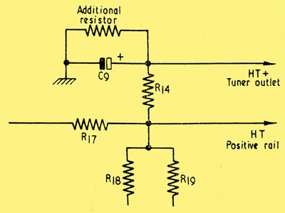
An alternative method of applying HT to the tuner unit.
An additional resistor is connected between chassis and the junction of R14 and C9, whereupon R14 forms the upper half of the potentiometer and the additional resistor the lower. The additional resistor may be mounted at the tuner unit.
The accompanying table gives values for R14 and the additional resistor for tuner units requiring 200 to 250 volts HT.
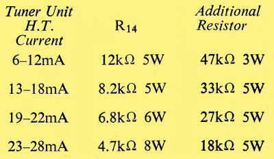
When the resistors are on nominal value the figures shown do not allow more than 0.8 of the HT voltage applied to R14 to be fed to the tuner unit under no-current conditions. Maximum tuner HT current is, in this instance, restricted to 28 mA because of circulating current in the potentiometer.
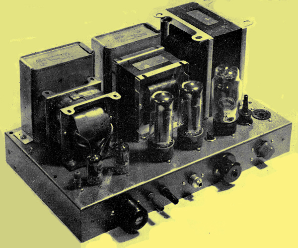
Top-chassis view of the amplifier with the cover removed.
|