|
As an alternative to a professional valve tester this project aims at accuracy through a bridge circuit. G A French provided a 'Suggested Circuit' in every Radio Constructor I have seen.

Although too much reliance should not always be placed on such instruments, it cannot be denied that valve testers and analysers are extremely useful items of equipment to have, both in the amateur and in the professional workshop. Unfortunately, commercially made valve testers tend to be rather expensive, the more elaborate models, in particular, incurring quite heavy outlays. Cheaper valve testers frequently check emission only, whereupon the information they provide concerning the valve being tested is not of great practical value.
The process of constructing a valve analyser, instead of purchasing a commercially made instrument, is quite a feasible proposition if carried out with a reasonable amount of care. A simplification is provided by the fact that a multiplicity of different valve-holders is not nowadays as necessary as it was before the war. Similarly, the provision of a large number of filament or heater voltages does not raise as many difficulties as have been apparent in the past. This is due to the fact that most modern valves which do not employ 6.3 Volt heaters or 1.4 Volt filaments are intended for connection in a series heater string. Such valves may then be accommodated by feeding them, from a suitably isolated AC supply of some 200 Volts or so, via series dropper resistors; the latter being switched to feed 0.15, 0.2 or 0.3 amp heaters as desired
The more difficult problems, so far as home constructed valve analysers are concerned, consist of working out a suitable type of test and of calibrating the instrument after it has been completed.
Mutual Conductance Test
Probably the most realistic check of the 'goodness' of a valve is given by measuring its mutual conductance. The mutual conductance, or gm of a valve, defines its change in anode current given by a change in grid voltage, the potentials of all other electrodes, other than the grid, remaining constant. In this country mutual conductance is expressed in terms of mA per Volt. In American literature mutual conductance is expressed in micromhos, the MHO being a unit of conductance. (A MHO is the reciprocal of an Ohm: a circuit having a resistance of 5 Ohms would have a conductance of 0.2 MHO). A gm of 1,000 micromhos is equivalent to one of 1mA per volt.
This months circuit illustrates a very simple means of measuring the mutual conductance of a valve under dynamic (i.e. non-static) conditions, and has the advantage of requiring no complicated or expensive gear for calibration. There are the incidental factors that the instrument can also provide checks for microphony and emission.
Principle of Operation
The analyser functions by applying an AC voltage to the grid of the valve under test and of converting the resultant AC current at the anode to a voltage; the voltages at grid and anode being then applied to a bridge in order to determine their ratio. The conversion of anode current to voltage is carried out by feeding the anode through a resistor, the value of this being kept very low.
To understand the functioning of the device more clearly, it might be worth while to commence by examining the simplified circuit shown below.
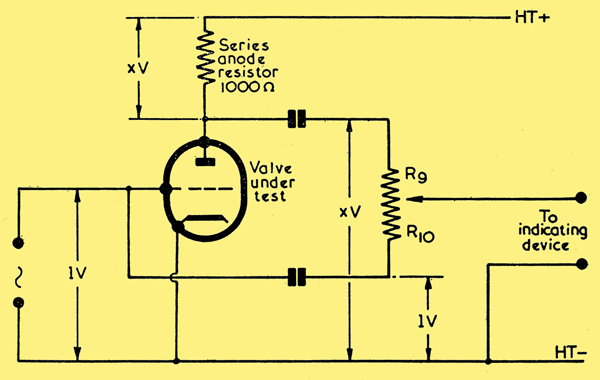
In this diagram the series anode resistor has a value of 1,000 Ohms; with the result that a change in anode current of 1 mA causes a change of 1 Volt to appear across this resistor. In consequence of this fact, if the valve under test has a gm of X mA per volt, we can assume for the moment that a change in grid voltage of 1 Volt will cause a change in anode current of X mA, together with a change of X Volts across the anode series resistor. These voltages are depicted in the diagram. Since the grid T and anode voltages are 180° out of phase it then becomes a very simple matter to apply them to a bridge potentiometer, as is done in the diagram, whereupon the arm of the latter can be adjusted for minimum output or null. The mutual conductance, in mA per volt will then be equal to the ratio, R9 / R10 It may now be seen, incidentally, that there is no real necessity to apply an input AC having a precise voltage to the grid of the valve, since the ratio R9 / R10 will hold good for any reasonable input voltage. If Y volts AC were applied to the grid, XY volts would appear across the anode resistor. In practice, however, it would be preferable to use as low an input voltage as could be detected by the indicating device coupled to the bridge, since this would prevent the possibility of swinging the grid over any non-linear part of the IaVg characteristic of the valve under test.
There is one disadvantage with the circuit above, this being the fact that the 1,000 Ohm series anode resistor has too high a value. If the circuit were used for testing a power valve with a high gm, the AC voltage appearing across the anode resistor would be excessive and would not allow the requirement that gm be measured with constant anode potential to be met.
This trouble can be obviated by making the series anode resistor small in value, say 25 Ohms. The AC voltage appearing across a resistor of this value would then be one-fortieth part of the voltage appearing across the original 1,000 Ohm resistor. If we next applied to the lower arm of the potentiometer R9, R10 one-fortieth part of the input AC applied to the grid of the valve under test, we would once more be able to balance the bridge, and the expression R9 / R10 would once again define the gm of the valve in mA per Volt. This is what has been done in the circuit which is discussed this month, and it is assumed that the error introduced by the presence of the 25 Ohm anode resistor is negligible for all valves normally encountered in radio and television receivers.
The Analyser
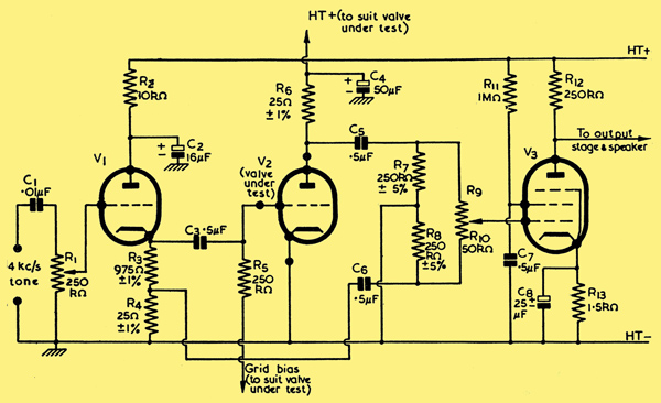
The full circuit
The full circuit of the valve analyser is given above. In this diagram the AC voltage is obtained from an audio oscillator or similar device which functions at a frequency around 4 kHz. (The reason for this rather high frequency will be explained shortly). The 4 kHz tone is applied to the volume control R1 and, thence, to the cathode follower V1. V1 may be any low-mu triode. The cathode load of V1 is 1,000 Ohms, and one-fortieth part of the voltage built up across this load is applied, via C6, to the lower end of the potentiometer R9, R10. (R9 R10 is a single component, of course, two circuit references being quoted in order to simplify explanation). The total output of the cathode follower is applied to the grid of the valve under test, V2, via C3. The anode of V2 is connected to the HT supply via R6, this being the 25 Ohm series anode resistor already discussed. The upper end of R6 is decoupled to chassis by C4. C4 is an important component in the bridge circuit and must have a low reactance. At 4 kHz a 50 μF capacitor (the value specified for C4) has a reactance of 0.8 Ohm, and this should be sufficiently low for our purposes here. The necessity for ensuring that C4 has a low reactance is, incidentally, the reason for employing an operating frequency around 4 kHz.
The voltage appearing at the anode of the valve under test is applied to the upper arm of the potentiometer R9, R10 via C5. R9, R10 is kept at chassis potential via the resistors R7 and R8, these being included to prevent noise as the potentiometer is adjusted. As will be seen, both ends of R9, R10 are connected to chassis via almost identical impedances.
The slider of R9, R10 is coupled to the grid of V3, this being a standard high-gain AF pentode. The voltage appearing at the anode of V3 is next applied to a conventional output valve and loudspeaker. The output circuit can follow normal practice and is not, in consequence, shown in the diagram.
Calibration and Use
The analyser is initially set up by fitting the potentiometer R9, R10 with a scale, and calibrating this directly in terms of the ratio R9 / R10. The latter may be determined with the aid of an Ohm-meter. When used, the valve to be tested is plugged into the V2 position, the correct HT and grid bias potentials applied, and R9, R10 adjusted for minimum tone in the speaker. The volume control R1 should be adjusted during this process to as low a position as is consistent with an accurate determination of the null point. Mutual conductance can then be read directly, in mA per volt, from the scale of the potentiometer.
Tests for microphony may be carried out by switching off the 4 kHz tone, setting R9, R10 to the top end of its track and tapping the valve under test. An emission test can be carried out by inserting a meter between R6 and the anode of the valve. This meter should be short-circuited whilst measuring gm. It will be apparent that it would not be possible, with this circuit, to supply the filaments of battery valves under test from a 50 Hz AC supply; this being due to the consequent introduction of hum. The simplest method of heating such valves would be by the use of a battery, all other voltages being provided, of course, from the mains power pack of the unit.
Little else concerning the practical aspect of the circuit needs to be emphasised, apart from the fact that the null point on the bridge will be masked if stray capacities exist between the bridge circuit and amplifier, and the circuit to the grid of the valve under test. However, it should be possible to keep stray capacities to a low value by employing normal sensible layout techniques.
Calculated Errors
Before concluding, it would be of interest to calculate the errors inherent in the circuit design. The main possible causes of error are the presence of C4 and of R6. The capacitor C4 has a reactance of 0.8 Ohms at the operating frequency of 4 kHz. Thus the impedance between the anode of V2 and chassis is equal to (252 + 0.82)0.5 = 25.03 Ohms; and the phase shift at V2 anode is approximately 2°. The resultant unbalance introduced into the bridge should be negligible and could be further reduced, if desired, by increasing the value of C4.
Inserting R4 in the anode circuit of V2 causes the dynamic mutual conductance of the valve to be gm / (1 + (R / Ra)) instead of being purely gm. Under the worst conditions, such as could be given by, say, a triode-connected 6F6 with an Ra of 2,600 Ohms, the dynamic mutual conductance becomes:-
gm / (1 + (25 / 2600)) or approximately gm / (1 + (1 / 100)) = gm + 1 / 1.01.
In this case, the error in reading given by the analyser would be approximately 1%. With most valves, the error would be far less than this figure.
See also Dynamic Mutual Conductance Tester
|