|
A Microprocessor Controlled Valve Tester
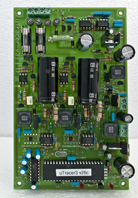
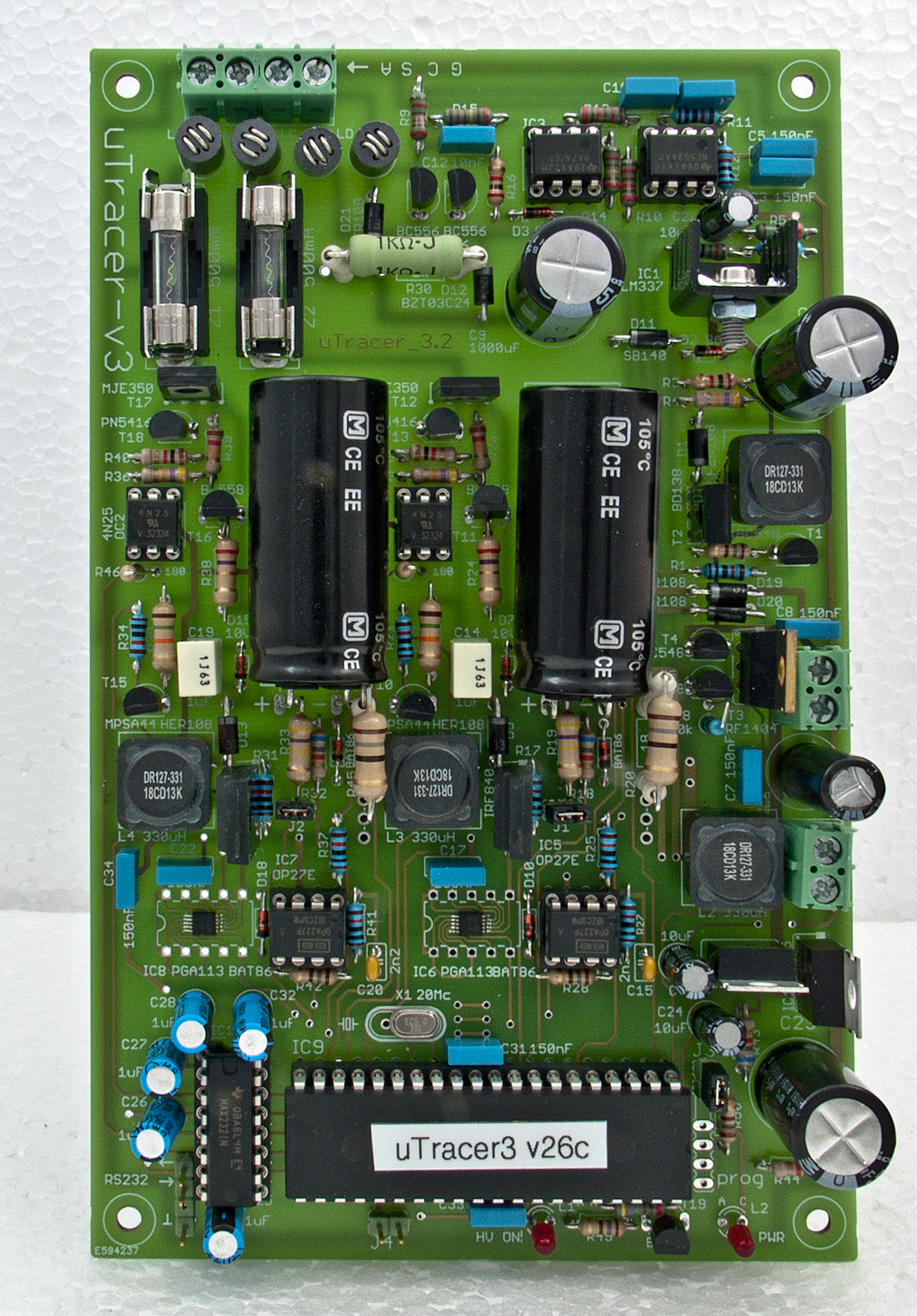
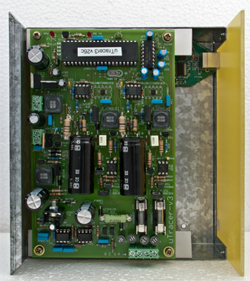
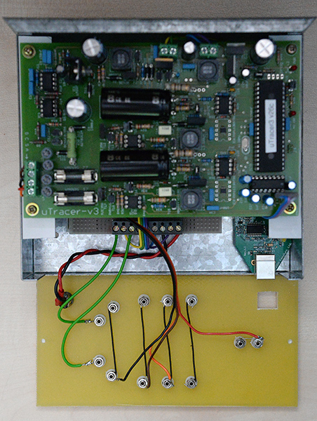
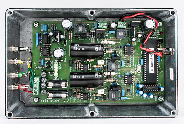
G8LSD's completed board. Click for large image.
The μTracer (search for utracer on Google) is a single board microprocessor controlled valve characteristic measuring tool. The μTracer has been designed by Ronald Dekker and kits are available from his website.
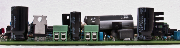
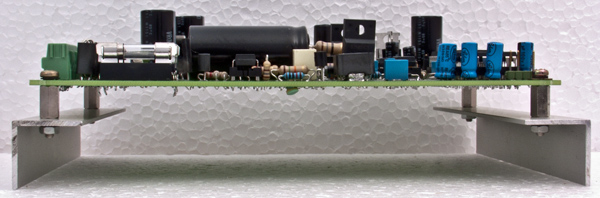
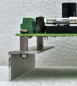
Profile of the board and connectors for power (left) and heaters (right).
All voltages, except the heater, are only generated for a millisecond or so - just long enough for a reading to be taken. In this way the valve under test is not driven too hard and lethal voltages are not permanently present.
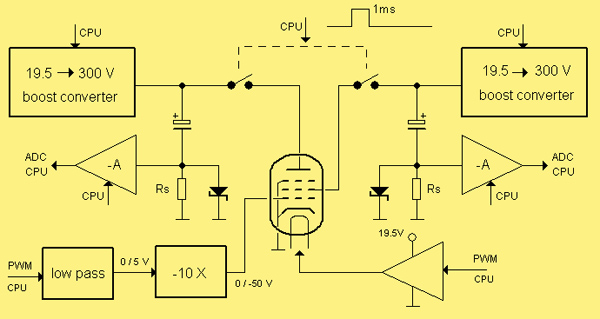
Block diagram of the μTracer from Ronald's website.
Construction of G8LSD's μTracer
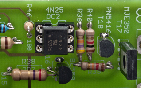
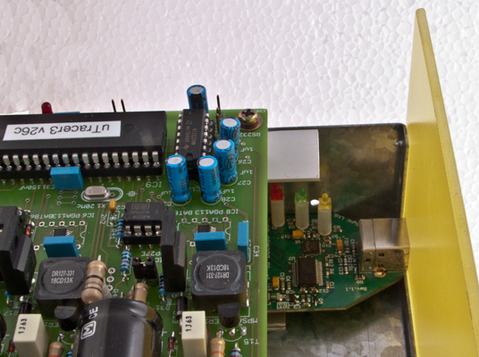
A small section of the board. Note the clear legend.
The kit comes with a detailed and comprehensive assembly manual. Construction is divided into ten stages: each is a case of build and then test before moving on. The professionally made board has very clear lettering and polarised components are clearly marked as to orientation. The fibre-glass board measures 162 x 100 mm and has wiring printed on both sides with plated through holes where appropriate. With a fine pointed soldering iron bit and 22 gauge cored solder the components are easy to assemble.
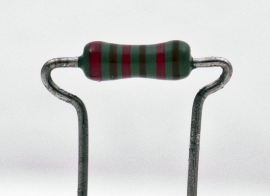
A resistor prepared for insertion.
I was taught, in the days of carbon resistors, to form component leads in a way that did not put strain on the ends of devices. The image above illustrates the method. The lead is held very close to the body of the component with the tip of the wireman's pliers and then the lead is bent over the tip of the pliers and almost back parallel with the body of, in this case, the resistor to form the first curve. The pliers are then inserted into the loop and the lead bent outwards again. In this way the leads are made as wide apart as required and they stand off the board for good air circulation.
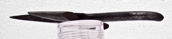
Wireman's pliers - obtained second hand in 1968. They are 130mm long and 46mm across the handles.
Operation of the μTracer is via a Graphical User Interface (GUI) running on a PC. This communicates with the microprossor on the board via an RS232C serial interface. Modern PC's and laptops without a serial port will need a USB to RS232C converter. I purchased mine from Farnell (UK supplier).
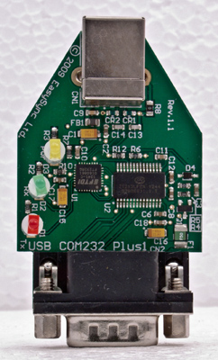
USB to serial board. This one has the correct chip set.
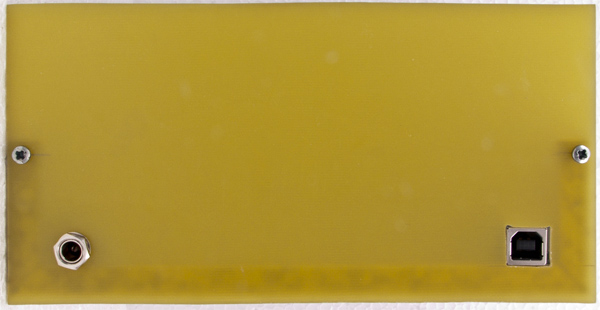
The 3 mm fibreglass front panel. Connectors fitted are for 20 Volts DC input power and the USB link to the PC.
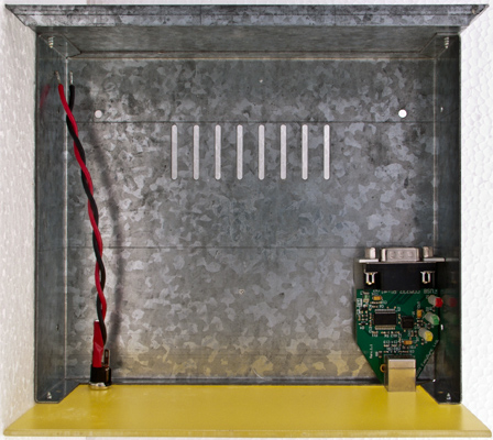
The inside of the galvanised steel chassis with USB module fitted.
Main board on aluminium angle with spacers.
The spacer has a stud one side and a thread the other.
The main board fitted. All aluminium brackets are held in place with two-pack apoxy adhesive.
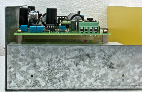
Fitted main board side view.
The front of the USB board rests in the front panel.
Final stages of construction of the main unit. The veroboard unit contains the input fuse and choke and the heater fuse and choke. Eight of the nine way terminal block connections are used. Ribbon wire connects to the main board. The connectors on the front panel are 2mm sockets.
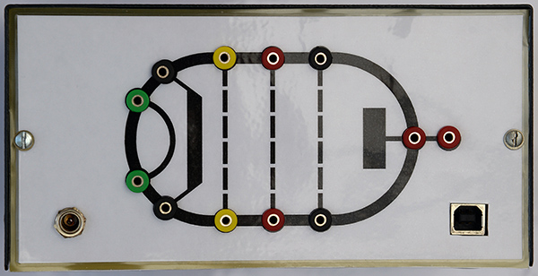
The completed front panel in place within the cabinet. Click for original artwork.
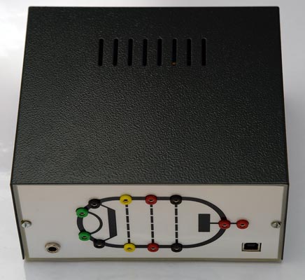
The completed main unit.
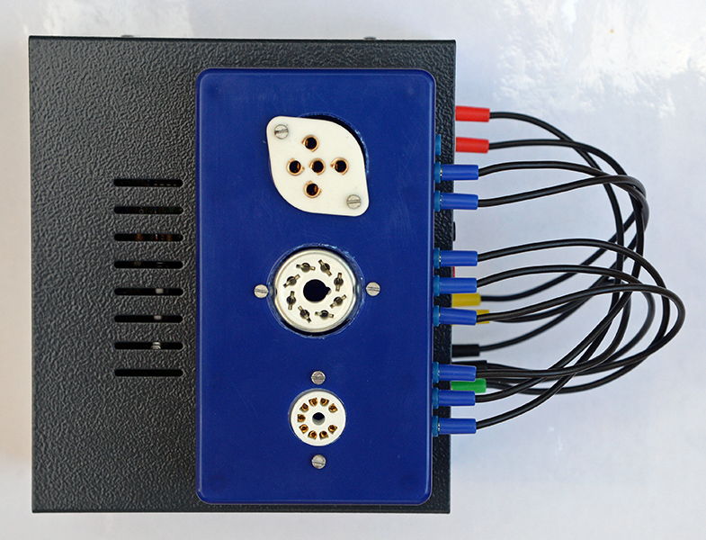
The valve holders are mounted in plastic boxes and held in place on the steel cabinet with magnetic strips.
The GUI almost fills a screen 1024 x 768 pixels and sub screens include a comprehensive calibration page that is saved to disc and ensures that voltages produced by the μTracer agree with the builder's own multi-meter. The calibration screen has a series of sliders that allow very precise control of the μTracer output.
Data produced by the tracer is shown as a graph and the plot values can be saved to disc.
In September 2014 I moved the calibration file to the Museum three screen HP computer and began to measure some valves. To be able to cover a wide range of valves, including some power valves, I purchased a cheap power supply to act as an external heater supply.
Once a particular valve Type has been correctly set-up it is simple to save the set-up for repeat use. Over time a library of types is therefore compiled. The plan is to measure some of the older valves for which we have no data-sheet and to select audio valves for demonstration projects.
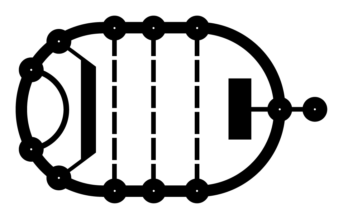
Having made leads to connect between the valve image on the tester and the nine sockets on the valve holder carrier it became quickly apparent that this was a very successful way of setting up for a new valve. The electrode ends of the leads are colour coded and the other ends are all blue. The heater leads from the external power supply have red and black plugs to make recognition easy.
Examples
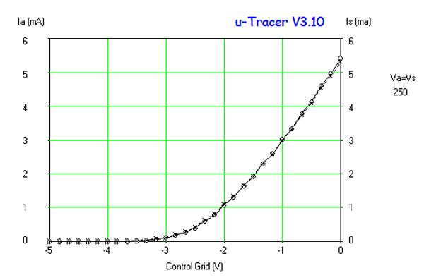
A plot of a good ECC83.
For plotting double triodes like the ECC83 above one anode connects to the anode supply and the other anode to the screen supply. The tracer then plots both sections at the same time. The plot above shows a closely matched pair of triodes. Sadly most that have been measured have poor in comparison.
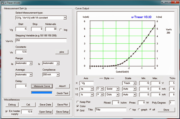
The screen display for the above graph.
A good general test to check the tracer itself is to plot a medium power valve such as the EL84, 6BW6 or KT61.
A set of curves for the KT61.
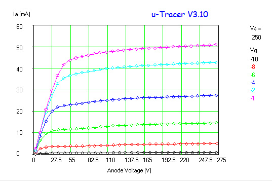
As the μtracer can supply 200 mA from the HT supplies the KT66 can also be measured well within the units capabilities.
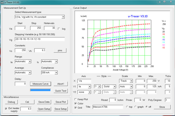
A set of curves for the KT66.
A useful feature is the Quick Test facility. This performs a set of measurements at a single bias point and after statistically verifying the set will evaluate the basic valve parameters of Ra, gm and μ together with a scale of anode current at the bias point v makers expected value. Such a test for the KT66 is given below.
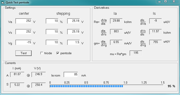
KT66 quick test window.
Problems and Solutions.
The tester works as expected most of the time but some valves produce erratic traces and were considered to be defective. In particular the EL84 was prone to the trace showing a jump and/or a decrease in anode current with increasing voltage.
A batch of five New Old Stock (NOS) EL95s purchased for a project all showed the erratic trace whereas an EL95 with poor emission had a perfect shaped trace. Some months later a batch of five 6J6As exhibited the same pattern. Only an ECC91 with low emission gave a correct trace.
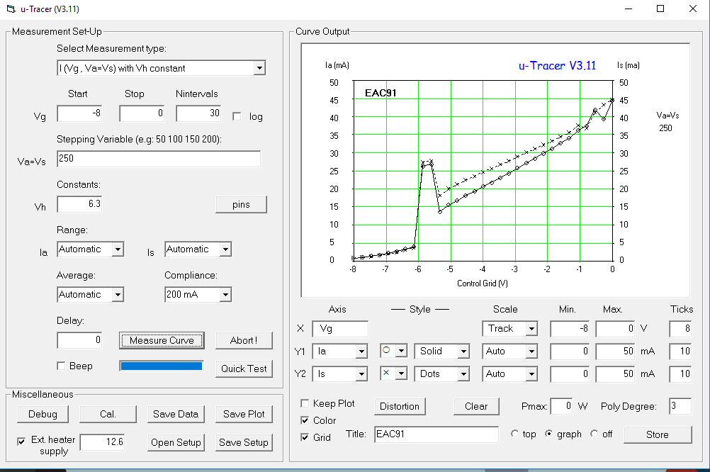
6J6A (ECC91) double triode with oscillations.
An afternoon of testing and retesting resulted in some 20 plots that were sent to Ronald for comment. His near instant reply was that the valve was obviously oscillating. Not knowing what an oscillating valve trace would look like I had missed this possibility. During construction precautions against oscillating had been taken and results suggested that these had been successful. Wrong.

6J6A (ECC91) triode another trace with the valve oscillating.
Ronald sent me his list of steps to take and I chose to add a stopper resistor as a first measure as ferrite beads were in place.
The following is guidance from Ronald:
Oscillations are a problem with any valve-tester/tracer, especially for high gain types. The oscillations have very much to do with the way the tubes are connected to the μTracer.
in general:
- use short wires
- create a loop wiring (see construction manual)
- insert RFI suppression beads
- insert a (1 to 10 kΩ) stopper resistor in the grid line
All these precautions have been taken in the AVO tester, but even there valves sometimes oscillate.
It is in itself no wonder, you bias tubes in their optimal bias point. Especially RF high gain valves will then want to oscillate if there are inductances in the interconnects. It is what they were made for!
I added a 10 kΩ resistor to the terminal plate of the μTracer in the control grid circuit as an initial approach and was initially delighted with the results. Later I found that RF valves like the 6J6A still oscillated.
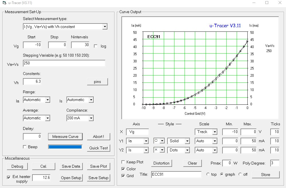
6J6A (ECC91) triode another trace without the valve oscillating.
One essential requirement in a piece of test equipment is that you must be able to trust the results. I had stopped trusting my version of the μTracer and so a rethink was required.
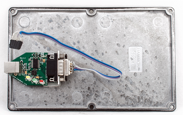
Shorter leads were obviously required and so I found a die-cast box that the board would fit into. For a perfect fit the middle pillars needed to be filed a little thinner and to give clearance for the valve connection sockets two corners of the board were filed down. The original stand-off pillars were sufficient to hold the board away from the base of the box and four holes were drilled for them.
The board inside the die-cast box. The corners of the board needed to be shaped to fit round the corner pillars.
To minimise the lead length from the tester two rows of four coloured 2 mm sockets were fitted as close to the connector on the board as possible. The box was high enough for the USB adapter to be fixed to the box lid and it just clears the power transistors on the main board. With a square hole in the end wall of the box the USB socket lies flush with the outside. The 2.1 mm power connector also fits in the end wall.
The USB to RS232 board mounted in the lid.
I have a 20 Volt 5 Amp switched mode bench power supply that I use for powering the heaters and so the μTracer board heater supply was not connected to sockets on the box. Whilst I was looking for causes of instability in the original build I purchased a small linear bench power supply and this is used to supply the DC input.
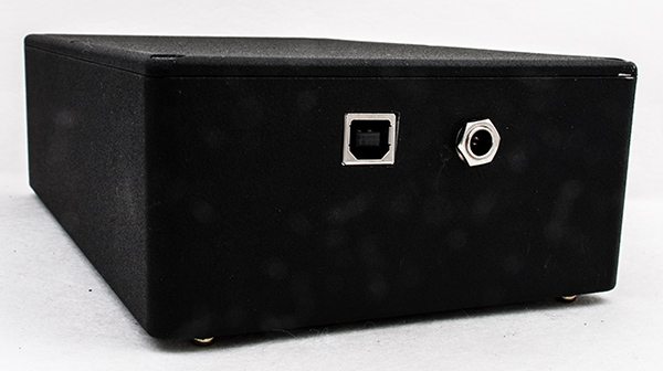
The rear has the USB and power input sockets.
The High Voltage indicator LED is connected to the board and cannot be seen with the box sealed. So in use the tester needs to be left a few seconds between measurements to allow the HT to drain away. Failure to do this results in an error and the need to re-boot the PIC.
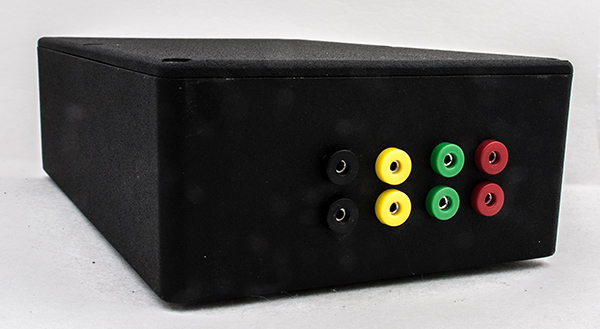
The connections are 2 mm sockets.
The valve socket boxes were left untouched as were the connecting leads. The newly housed μTracer was powered up and tested by following the tests in the construction manual. It was immediately apparent that nothing worked. After much head scratching it was found that the -40 Volt line was at -40 Volts and the -15 Volt line was also at -40 Volts. The LM337 had failed to a short circuit. Replacing the LM337 restored the -15 Volt line but still nothing worked except the HT voltage generators. The strange readings on the grid negative rail suggested that the circuit was dead. Four op-amps use the -15 Volt rail and it looked a good bet that all four had been destroyed. Replacing the op-amps brought the tested back to full operation. The LM337 is run close to the limit and the new regulator fitted was an LM337T that the data-sheet indicated was good for inputs up to -50 Volts.
With all of the op-amps replaced the tester sprang to life and all tests and calibrations gave the correct results.
Using an EL84 as a test valve the initial result was encouraging but with full specification valve the trace still jumped - it was still oscillating. The leads used from the tester to the valve base box are of very flexible test lead wire and in the junk box was a large ferrite ring from an old switch mode power supply that I could wrap a single turn of wire round. With the anode lead passed through the ferrite most of the oscillation ceased but occasionally the tell tale trace would appear. Finally I wrapped a loose single turn of the control grid wire through the ferrite along with the anode lead. This was done in desperation more than anything but the results indicated progress.
I have subsequently tested more than 100 valves from RF valves to audio valves, all upon the B9A base, and no sign of oscillation has been found. Some high gain valves have been tested again and again over the past week and none have oscillated.
|