|
The Suggested Circuit presented in The Radio Constructor of of June 1956 has always seemed a useful piece of test equipment. Here an up to date implementation is realised.
The original is a bridge circuit operating at 4 kHz where the reactance of the blocking capacitors is small and where a small resistor in the anode circuit is used to generate the voltage to compare with the reference. As the valve inverts the signal the two sine waves can be made to cancel as the bridge is balanced.
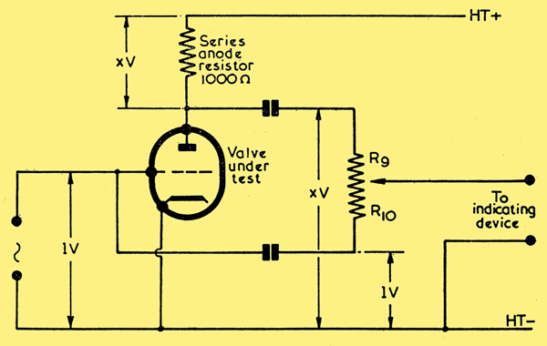
The basic principle used in the tester.
Mutual conductance is specified with a constant anode voltage and thus the anode sense resistor needs to be small so that the voltage generated is negligible compared to the HT voltage. 25 Ω was chosen in the original and the preferred value of 22 Ω has been used in this implementation.
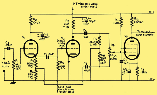
The original circuit.
A 3038 function generator kit was built to provide the required 4 kHz sine wave. The output is fed to a 100 kΩ potentiometer. It was planned to use a small B7G based triode for the cathode follower, a 12AT6 with a 12.6 Volt heater would match the DC to the function generator. The 600 mW valve amplifier would complete the project. However, it was subsequently decided that updating the design might be more appropriate.
The function generator kit mounted on a piece of copper clad board.
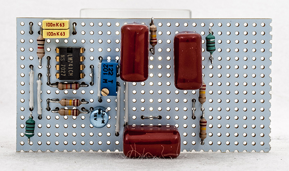
In place of the cathode follower a 741 inverting amplifier operating from the single 12 volt rail was built. C1 is a 2.2 μF tantalum electrolytic capacitor. R1 10 kΩ. The potential divider R3 and R4 are a pair of 220 kΩ resistors. The function generator output gave 810 mV RMS to the sine wave port and to offer some headroom to the grid signal the op amp gain was set at 2.7 by making R2 27 kΩ.
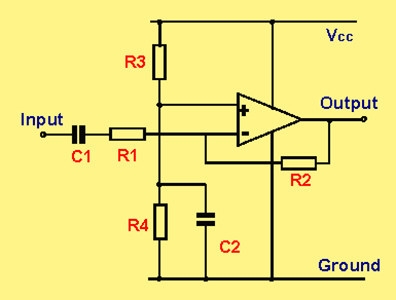
A basic inverting op-amp circuit.
It will be seen in the original design that the bridge reference signal is one-fortieth of the grid signal in order that a low value anode sense resistor can be used. The accuracy of the divider is important and 22 Ω resistors are not easy to measure accurately with an Ohm meter as the last digit can be in error. To obtain a matched pair, a 1 kΩ resistor was placed in series with the test resistor and the pair connected to the 50 Ω output of the workshop function generator. With the oscilloscope connected across the test resistor the voltages were measured for a series of resistors until a close matched pair were identified.
For the actual circuit a 1 kΩ multi-turn potentiometer was connected as a simple variable resistor in series with the 22 Ω resistor across the op-amp output and with the two channels of the oscilloscope the grid and reference voltages were established. In practice with 2 Volts RMS applied it was simple to set accurately.
With modern components obtaining 1 μF 400 Volt capacitors was easy and these were substituted for the original 0.5 μF ones. At 4 kHz the reactance is 40 Ω. The 50 μF HT bypass capacitor was selected as a 47 μF 450 Volt type.

A complete circuit drawn by Attila Balaton in 2020.
Attila has made some additional changes in his circuit shown above. The C1 coupling capacitor has been reduced to 0.22 μF. This reduces low frequency transmission into the circuit. A sensible precaution has been the addition of a 10 kΩ grid stopper resistor to reduce the risk of oscillation.
A plastic case 150 x 80 x 50 mm was to hand and the card slots were the correct size to take strip-board that was to hand cut in half. The op-amp circuit and main components fitted on one piece and the other half was used to build a simple audio amplifier based around the LM380 - a component from the Junk Box.
The op-amp and bridge components before the fitting of connecting pins.
The board shows two 1 mH chokes used for the low value resistors. These were matched for a 25 Ohm reactance at 4 kHz and were selected from a batch of ten. Initial results were successful but one of the inductors went open circuit and the decision was taken to revert to the 22 Ohm resistors.
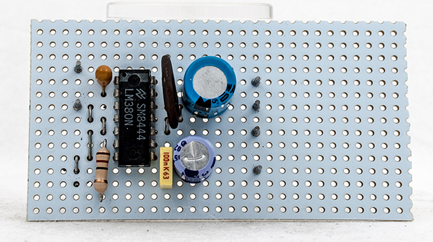
The LM380 audio amplifier.
The LM380 amplifier was used during the bread-board stage and the noise produced was uncomfortable. My wife and I share our garden office and it rapidly became clear that using the audio amplifier was not going to be acceptable. With the oscilloscope present above the bench a different indication of bridge balance was easy to select. At very low signal levels the trace cannot remain locked to the timebase. Using the square wave output from the signal generator as a reference to the second channel introduce annoying spikes on the wanted trace. Moving to the triangle wave output as the locking reference was the answer.
Part way through construction. The flying leads on the multi-turn potentiometer allowing for calibration.
A ten turn potentiometer of 1% accuracy and 50 kΩ total resistance together with a turns counting dial - just right for the project had been in the workshop for some years. Readings of resistance were taken for calibration but for greater accuracy the measurement of a 4 kHz sine wave was subsequently evaluated at 100 points. With the dial position and voltage readings entered into a spreadsheet the ratio was calculated and a graph drawn as well as a chart being printed.
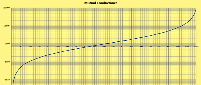
The calibration graph. Log(10) gm against linear rotation.
It was always planned that the many bench power supplies available would provide the voltages for the tester - 12 Volt for the internal circuits, low voltage variable for the heaters and a third low voltage variable supply for the grid bias. The HT is taken from a Heathkit regulated HT supply. Using the valve base boxes made for the μ-Tracer avoided duplication.
Decoupling was provided at each board but the high impedance circuitry easily picked up mains hum. It would have been better to have built the tester into a sealed die-cast box and used screened cables for the signal paths. Even without these precautions the tester proved successful and a joy to balance. Initially it was considered that a ten turn potentiometer would give too much resolution and the balance point would not be reproducible to within close tolerance but in practice the null point is quite clear.
Testing was carried out with ECC81, ECC82 and ECC83 all previously tested with the μ-Tracer. The traces below are from an ECC81. With the HT switched off the trace shows the reference sine wave that is in phase with the triangle wave. The second trace is dominated by the inverted signal from the anode circuit. The final trace shows the bridge in balance. In all three cases the noise has been reduced by connecting the spare 1 mH choke in series with the oscilloscope probe.
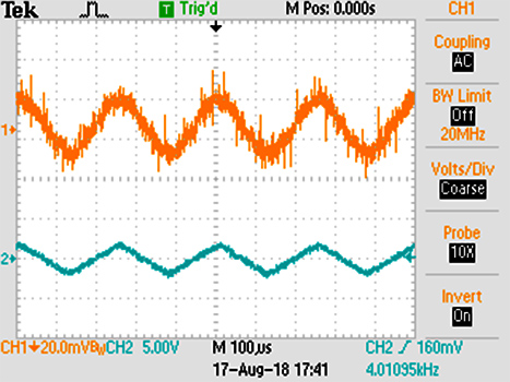
Tektronix TDS2012. No HT to valve.
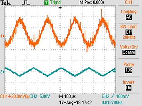
Tektronix TDS2012. HT to valve - bridge unbalanced.
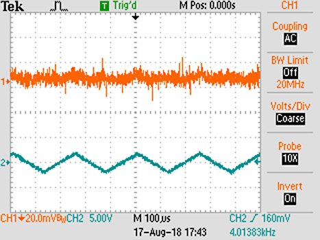
Tektronix TDS2012. HT on and bridge in balance.
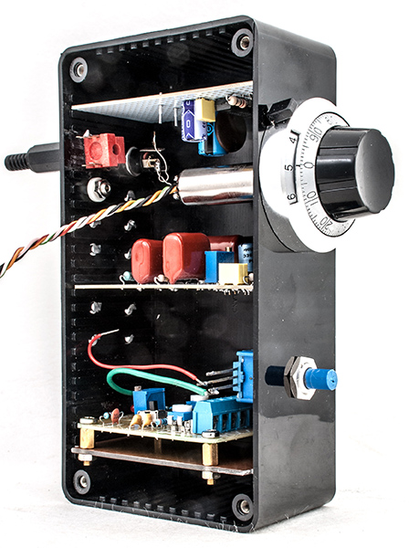
Front panel.
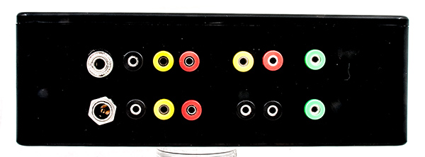
Rear panel.
Left right top row - 3.5 mm jack socket to balance indicator, valve cathode, valve grid, valve anode, negative grid bias, HT and reference triangle wave. The coloured sockets are all take 2 mm plugs.
Left right bottom row - 2.1 mm DC socket, valve cathode, valve grid, valve anode, grid bias ground, HT ground and reference triangle wave ground.

The completed tester.
The 47 μF HT capacitor is mounted directly on the HT terminal lugs.
|