|
Test and Measuring gear and its Uses.
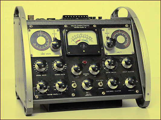
We have the AVO Mk IV tester in the museum.
A valve tester is a device that gives sufficient indication of the all-round goodness of a valve for an observer to ascertain whether the valve is going to perform satisfactorily in a wireless set or amplifier. For such purposes the goodness of a valve is dependent upon several factors, of which the chief are:-
- the emissivity of the cathode;
- the degree of vacuum inside the glass envelope;
- in the case of indirectly heated cathode valves used in mains sets, the insulation between heater and cathode, particularly when hot, as in working conditions; and
- the mechanical condition of the electrodes inside the glass envelope, including their insulation from each other.
It is perhaps best to consider each of these factors separately at first in order to perceive how, in commercial valve testers, ingenious arrangements enable their effects to be observed by the movement of a pointer across a meter dial, Taking the last-mentioned factor first - the mechanical condition and insulation of the electrodes - the testing of this factor is very simple. A valve with mechanically defective electrodes will, save in rare cases, be 'microphonic' - that is, it will set up anything from crackles when tapped to continuous howling as soon as the set is switched on. Modern manufacturing processes have gone a long way towards making electrode structures strong and rigid, and towards attaching the various parts of the structure to each other very firmly - usually by spot welding - but perfection is impossible; a turn of the control grid may become detached, or a strut of the anode, and hang loose or ready to vibrate with the slightest jar; overheating, even of short duration, of the filament of a battery valve may cause it to sag without breaking and become vibrant when jarred. There is no quantitative test possible, or needed, for valve microphony - the ear is a sufficiently competent tester, if the valve is lightly tapped.
Inter Electrode Insulation
The insulation between the electrodes of a valve is best tested by some sort of Megger or neon circuit, since it must be extremely high to be satisfactory. Several commercial valve testers have something of the sort incorporated, for the preliminary test of a valve in this respect before its insertion in the tester, since a short-circuit between electrodes might damage the tester.
Taking the matter of cathode-heater insulation next, this is a factor that can be measured quite accurately. It is essential, however, that it should be measured 'hot' as well as 'cold' and, if possible, with working voltages applied to the other electrodes. This is because leakage paths between heater and cathode quite often do not appear until the normal working heat has expanded the parts involved. Tested when cold, the insulation between cathode and heater may appear quite satisfactory - i.e., some 1 MΩ at least, and usually very much higher; as soon as the valve is put back into the receiver and used, it may give rise to intolerable hum. It would, of course, be possible to test hot cathode-heater insulation directly with a fairly obvious arrangement insulating the heating source very carefully from the cathode. But a rather simpler arrangement from a practical viewpoint, especially when mains supplies are used for power, as is usual in valve testers, is given in Fig. 1.
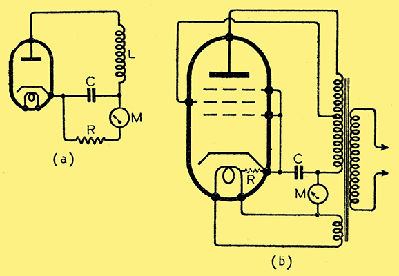
Fig. 1. (a) Indirectly heated diode 'leak and capacitor' rectifier. (b) Circuit showing how the same principles are used to indicate faulty cathode-heater insulation in a valve when the cathode is hot, as in normal operation.
How it works may be understood by reference to Fig. 1 (a), which is that of a simple diode with a leak and capacitor. When an alternating voltage is developed across the coil L, the capacitor C becomes charged on account of the rectifying action of the diode and discharges through the leak resistance R, which normally is included deliberately in such a circuit as this. A sensitive micro-ammeter in series with R, as shown by M in Fig. 1 (a) would measure the value of the discharge current. A similar principle is involved in the circuit of Fig. 1 (b). Here, the required alternating voltage is supplied by the secondary of a mains input transformer (of which another secondary provides the heater supply in addition) and the leak resistance R is provided by the leakage path, if any, between cathode and heater, as shown in dotted line. If insulation is good, i.e., R is very high, little, if any, movement will be observed of the pointer of the meter M, the dial of which may even be calibrated, if desired, in terms of meg-Ohms leakage. The valve under test - in the circuit shown it is a pentode - is being made to act as a rectifier.
Softness
The vacuum inside the envelopes of modern valves is extremely high, except in the case of special types such as certain power rectifiers, neon types, etc. The slightest crack in the envelope, even if invisible, or defect in the sealing between the glass and the leads-out of the electrodes, lets in sufficient air to ruin this vacuum. Moreover, the heating of the electrodes when the valve is in use may cause them to release a residuum of occluded gas. Elaborate precautions are taken against it, of course, in manufacture, but valves are still liable to 'go soft' in this way.
The easiest way to test a valve for softness is to measure the anode current with and without a high-resistance between the control grid and the cathode. If the vacuum is satisfactory, the presence or absence of high resistance (say 2 MΩ) between grid and cathode should make no appreciable difference to the anode current. If the valve. is soft, however, the anode current will not be the same in both cases; with high resistance in the grid circuit, the anode current will be greater than when the grid is returned directly to cathode.
Finally, there is the factor of emissivity of the cathode which, apart from anything else, determines inevitably the life of a valve. Most modern receiving valves are expected, if used normally, to have a satisfactory operational life of about 1,500 hours, although a lot depends on how much distortion or other falling off in performance a user is willing to tolerate.
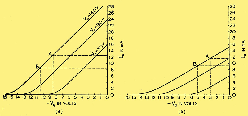
Fig. 2. (a) and (b) are Ia/Vg characteristics with normal and low cathode emissivity. Note the change in the slope of the lines AB in each case.
The important effect of loss of emissivity lies in the change it makes in the slopes of the families of characteristic curves. Two main families of curves are outlined in Figs. 2 (a) and (b), and the thing to note about them is that a change in cathode emissivity makes a change in the slope of the lines to a greater extent than does a change of any of the other parameters. Now, the constants of valves, μ, Ra, and Gm, are derived from the slopes of the characteristics; hence change in the emissivity of the cathode affects the valve constants considerably.
A few commercial valve testers merely test the emissivity of the cathode, without attempting to give any idea of the slope of any characteristic. It is assumed that if a valve does not pass the normal anode current when the filament or heater current, and the voltages applied to the other electrodes, are normal, the slopes of the characteristics will be altered. As a rough check on the condition of a valve, this is often good enough.
Instruments of this class are comparatively simple in construction, require only rneters of a very moderate order of sensitivity, and are easy to use. When mains driven, they consist of little more than a transformer with multi-tapped, secondaries for filament or heater supplier and for HT voltages to the other electrodes, a table being given for switching to the correct taps for the various types of valves to be tested. The valve being a unidirectional current device, the registering .meter is merely a DC moving-coil instrument. A skeleton circuit showing the principles is given in Fig. 3.
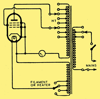
Fig. 3. Circuit showing a simple form of cathode emission valve tester, using AC only.
The scale of the meter is usually marked arbitrarily and is used with a table of the deflections to be expected with various types of valve.
Another form of valve tester does reveal approximately the slope of the Ia/Vg characteristic, by showing the amount of alternating current component developed in the anode circuit of a valve when a standard alternating voltage is applied to the grid. The principle is shown by the circuit given in Fig. 4.
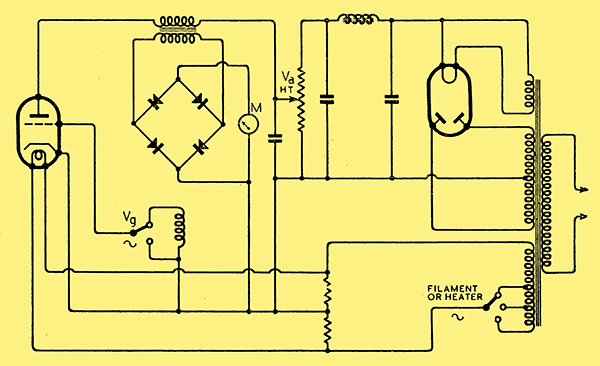
Fig. 4. Simplified circuit of a form of valve tester that registers the effect, in a rectifier type AC meter, of the AC produced in the anode circuit of a valve by the application of a suitable alternating voltage to the grid.
It will be evident from a consideration of the Ia/Vg characteristic shown in Fig. 2 (a) that the application of an alternating voltage, to the grid of a valve having this characteristic, of a value of about 0.75 Volt RMS will produce an AC component superimposed on the steady DC flowing in the anode circuit (with 140V as Va of about 2 mA RMS. If, however, the slope is less steep, as in Fig. 2 (b), the same Vg will produce only about 1.5 mA.
To make the point clearer, it will be assumed first, referring to Fig. 4 in conjunction with Fig. 2 (a), that the grid of the valve is not excited from the voltage developed across the coil L1, but is kept steady at -9.5 Volts, while Va is 140 Volts. A steady current will flow through the primary of the meter transformer, at 10.5 mA. Since this current is perfectly constant, no voltage is induced across the secondary of the transformer and the meter will, therefore, register zero. Now if the grid is connected to a tap on coil L1 such that the potential on the grid rises to -8.5 Volts, returns to -9.5 Volts, falls to -10.5 Volts, and returns again to -9.5 Volts - as would happen if the voltage developed by this tap on L1 developed a sine-wave alternating voltage of 1 Volt peak to peak (0.707V. RMS) - the current through the transformer primary would no longer be steady; it would start at 10.5 mA, rise with the grid voltage to 12.5 mA, return to 10.5 mA, fall to 8.5 mA, and return again to 10.5 mA. That is, an alternating component of a peak to peak value of 4 mA would appear in the current through the transformer primary, and this component would induce a voltage across the secondary that would operate the meter M. Applying the same alternating voltage to the grid of a valve of which the Ia/Vg characteristic had a less steep slope, as in Fig. 2 (b), would produce an alternating component of less than 3 mA with corresponding smaller effect on the meter.
In practice, of course, a valve tester of this type is mains driven, and L1 consists conveniently of a winding on the mains power transformer, developing 0.5 Volt RMS i.e., a peak to peak grid voltage swing of 1.4 volts - and the resulting alternating current component occurring in the anode circuit, varying in amount according to the slopes of the valves being tested, is registered on the rectifier-type meter M. Since manufacturers valve data regarding mutual conductance (which is the slope of the Ia/Vg characteristic) is normally given with mean Vg = 0, no standing bias need be provided. Tables are provided to enable the testing conditions for each type of valve to be set up by use of control knobs and switches, and the meter dial may be marked in terms of mutual conductance.
Another type of valve tester measures the slope of the Ia/Vg characteristic directly - i.e., the actual change in anode current brought about by a change of grid potential of 1 Volt is measured. Ingenious use is made of alternating voltage alone, without the complications of providing DC for both anode and grid voltages. Before considering the simplified circuit of this type, given in Fig. 6, the main principle can be grasped by a study of the circuit given in Fig. 5. in which DC is supposed to be employed.
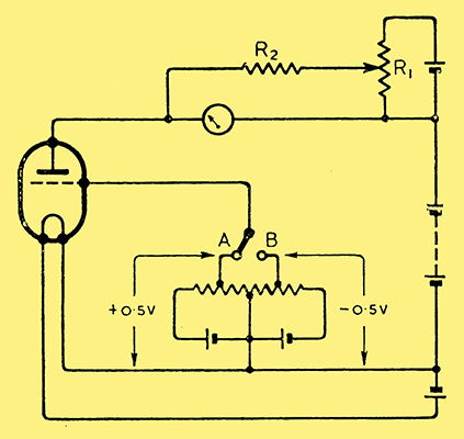
Fig. 5. Circuit showing principle employed in measuring the mutual conductance of a valve with DC power supplies.
The grid of the triode valve that is supposed to be under test is taken to a bias source that can provide a grid potential relative to the filament of either ±0.5 Volt. When the switch connects the grid to 0.5 Volt negative, the anode current is a certain I1 as registered on the meter. If the grid is then switched to 0.5 Volt positive - a total change of 1 Volt - the anode current will change to I2. Then the mutual conductance in terms of mA/V is (I2 - I1) mA per volt.
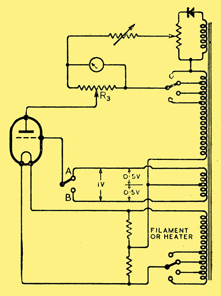
Fig. 6. Simplified circuit of a valve tester using alternating supplies to provide the working voltages for measurement of mutual conductance.
Backing-off Circuit
This simple arrangement, apart from anything else, has one serious snag: if the valve under test is, say, a power output type passing a standing Ia of the order of 20 or 30 mA, the small change of Ia which is the important factor - will not be easily or accurately observed on a meter that is capable of passing such a heavy current. To enable a sensitive meter to be used, therefore, which will be capable of giving a large readable deflection with or change of Ia of less than 1 mA, a backing-off circuit is provided, formed by a cell, in series with the positive end of the HT battery, with a potential divider, R1, across it. The sides of this potential divider is adjusted, with the valve passing anode current when the grid is switched to 0.5 Volt negative, so that the voltage developed across the meter (through R2) from this backing-off circuit is exactly equal and opposite to the PD set up across the meter itself by the passage of anode current through it. The meter then gives no deflection. As soon, however, as the grid is switched to 0.5 Volt positive, the increase of anode current is registered on the meter, since the PD across the meter due to this increase of current becomes greater, whereas the voltage due to the backing-off potential divider remains the same as before. Thus, even a change of a fraction of a milliamp. of Ia readily observed on a sensitive meter without it being affected by the passage of heavy current. The resistance R2 should be many times greater than the resistance of the meter in order to avoid an excessive shunting effect.
From the foregoing, the operation of the circuit of Fig. 6 can be derived. Referring to this figure the anode voltage is obtained from a HT secondary winding suitably tapped on the mains input transformer, as is the heater or filament supply from another tapped winding. The valve, therefore, only passes anode current during the positive half-cycles of voltage at the anode end of the secondary winding. How much anode current it passes depends on whether the grid is connected by the switch to the 'in-phase' or the 'out-of-phase' side of the centre tapped winding (additional to the two previously mentioned), that supplies grid potential. In-phase and out-of-phase refer to the polarity of the grid potential in relation to the anode potential; i.e., if the grid is positive when the anode end of the HT winding is positive, it is in-phase and vice versa.
Assuming, then, that the valve is in position and that suitable anode and filament voltages have been selected by the switches, the procedure is on the following lines: first, the grid is switched to the out-of-phase end of the grid voltage winding, say at B; the resulting standing anode current (actually, of course, unidirectional pulses of current each positive half-cycle at the anode end of the HT secondary) is backed off by the adjustment of the slider of a potential divider across a continuation of the HT winding until the meter registers zero. Then the grid is switched to the in-phase end of the grid voltage Winding at A; this changes the effective grid potential by 1 Volt in the positive direction, and the resulting increase of anode current is registered on the meter. The function of the half-wave rectifier in the backing-off circuit is to prevent a reverse current flowing through the meter during the negative half-cycles in the HT and backing-off windings.
The shunt potential divider R3 across the meter may serve two purposes. One is to adjust the sensitivity of the meter circuit to suit various mutual conductance constants. The other may be to provide means of showing the state of a valve in a rough but attractive way by colourings or similar devices on the meter scale. The slider of this shunt potential divider is adjusted, by reference to a table or dial markings, to such a position that, if the increase of current brought about by the switching of the grid from the out-of-phase to the in-phase connection is normal, the meter is sensitive enough to give nearly a full scale deflection - or, for instance, for the pointer to swing over to a part of the meter scale marked 'Good' or coloured brightly. If, however, the increase of current is below normal - indicating a less steep Ia/Vg characteristic, probably due to loss of cathode emissivity - the pointer only swings as far as the 'Indifferent' or 'Bad' part of the meter scale, or an appropriate colour which much impresses the lay customer, in whose view 'meters do not lie'! Plainly, much depends on the accuracy with which the slider on the meter shunt is adjusted.
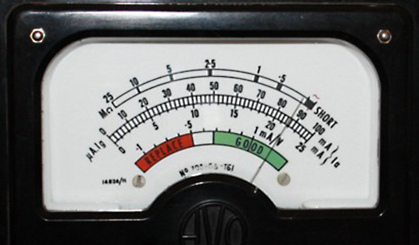
AVO Mk IV meter.
For the rest, rapidity and ease of preparation for test of many valve testers are facilitated by various forms of semi-automatic switching by means of perforated cards, numbered switches, etc., that also tend to make such instruments almost fool-proof. When a number of valves, of many different types, have to be quickly tested, such devices are of considerable and quite satisfactory service.
|